Viper 5806v Remote Start, Land Rover TDI Diesel
Printed From: the12volt.comForum Name: Car Security and Convenience
Forum Discription: Car Alarms, Keyless Entries, Remote Starters, Immobilizer Bypasses, Sensors, Door Locks, Window Modules, Heated Mirrors, Heated Seats, etc.
URL: https://www.the12volt.com/installbay/forum_posts.asp?tid=145799
Printed Date: May 14, 2026 at 10:00 AM
Topic: Viper 5806v Remote Start, Land Rover TDI Diesel
Posted By: itolond
Subject: Viper 5806v Remote Start, Land Rover TDI Diesel
Date Posted: November 23, 2019 at 11:32 AM
Hi Forum,
installing a 10 pin remote start in a land rover TDI diesel. Just want a Quick sanity / red flag check to make sure I am not off base...
Viper 10 PIN remote Start harness
Red/Black: (+) 12V INPUT - >To 12 volt constant (main power supply)
Pink/Black: FLEX RELAY INPUT (#87a of the onboard 2nd Ignition) -> Not used (specific vehicles - no 2nd ignition in this vehicle)
Pink/White: IGNITION 2/FLEX RELAY OUTPUT --> not used (no 2nd ignition in this vehicle)
Red: (+) 12V INPUT: (power feed for the onboard Ignition relay.)--> This looks the same as Red/Black above (constant fused power), this vehicle is not fitted with an ignition relay
Green: STARTER INPUT: (87a) --> to crank (starter) on ignition switch
Violet: STARTER OUTPUT: -->to starter relay (pin 85)
Orange: ACCESSORY OUTPUT:--> Replaces ACC output on ignition switch (in place of ignition switch - Landrover use 60A for supply, I notice Viper is fused @ 20A - issue?)
Red/White: (+) 12V INPUT (power feed for the onboard Ignition 2): --> connects to constant 12v (similar to Red/Black)
Pink: IGNITION INPUT/OUTPUT: connects to ignition out (replaces Ign pin on ignition switch)
Question A: wiring diagram ...Starter relay refers to a 5pin Starter Disable relay (87a) which would be an easy swap out - why and any advantages/ disadvantages (
Question B: Ignition 2, does this refer to ignition live from the ignition switch (et. runs the fuel solenoid on the diesel)
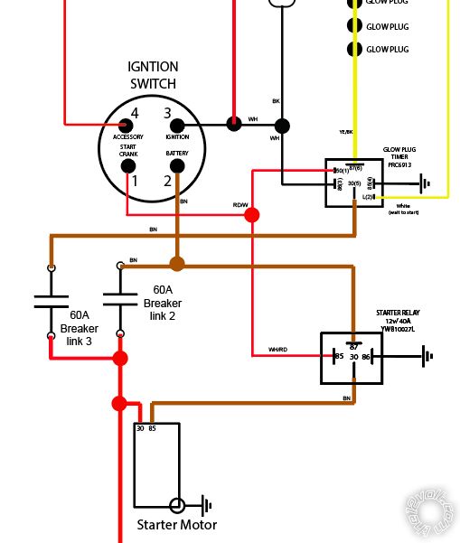
below is a simplified wiring diagram for the vehicle for reference:
installing a 10 pin remote start in a land rover TDI diesel. Just want a Quick sanity / red flag check to make sure I am not off base...
Viper 10 PIN remote Start harness
Red/Black: (+) 12V INPUT - >To 12 volt constant (main power supply)
Pink/Black: FLEX RELAY INPUT (#87a of the onboard 2nd Ignition) -> Not used (specific vehicles - no 2nd ignition in this vehicle)
Pink/White: IGNITION 2/FLEX RELAY OUTPUT --> not used (no 2nd ignition in this vehicle)
Red: (+) 12V INPUT: (power feed for the onboard Ignition relay.)--> This looks the same as Red/Black above (constant fused power), this vehicle is not fitted with an ignition relay
Green: STARTER INPUT: (87a) --> to crank (starter) on ignition switch
Violet: STARTER OUTPUT: -->to starter relay (pin 85)
Orange: ACCESSORY OUTPUT:--> Replaces ACC output on ignition switch (in place of ignition switch - Landrover use 60A for supply, I notice Viper is fused @ 20A - issue?)
Red/White: (+) 12V INPUT (power feed for the onboard Ignition 2): --> connects to constant 12v (similar to Red/Black)
Pink: IGNITION INPUT/OUTPUT: connects to ignition out (replaces Ign pin on ignition switch)
Question A: wiring diagram ...Starter relay refers to a 5pin Starter Disable relay (87a) which would be an easy swap out - why and any advantages/ disadvantages (
Question B: Ignition 2, does this refer to ignition live from the ignition switch (et. runs the fuel solenoid on the diesel)
below is a simplified wiring diagram for the vehicle for reference:
Replies:
Posted By: kreg357
Date Posted: November 23, 2019 at 12:21 PM
Greetings!
Not sure of the vehicle year, etc. Don't think we get L.R. diesels in the states, but...
Red/Black: (+) 12V INPUT - >To 12 volt constant (main power supply)
Pink/Black: FLEX RELAY INPUT (#87a of the onboard 2nd Ignition) -> Not used
Pink/White: IGNITION 2/FLEX RELAY OUTPUT --> not used
Red: (+) 12V INPUT: (power feed for the onboard Ignition relay.)--> To 12 volt constant (main power supply)
Green: STARTER INPUT: (87a) --> not used *
Violet: STARTER OUTPUT: -->to starter relay (pin 85) or ignition switch Pin 2
Orange: ACCESSORY OUTPUT:--> To ignition switch Pin 4 If you have a DC Amp meter capable, check
to see current draw while running with all accessories running. A/C, fans, wipers, radio, etc.
Red/White: (+) 12V INPUT (power feed for the onboard Ignition 2): --> not needed as no IGN2 used
Pink: IGNITION INPUT/OUTPUT: connects to ignition out Pin 3 (replaces Ign pin on ignition switch)
* If you wanted Starter Kill / Anit-grind you could use this Green wire. You would cut the vehicles
Starter wire, Pin 1, near the ignition switch, connect the Green to the side going to the switch and the Violet
wire to the side going to the starter relay.
With a diesel, you should program in a diesel start delay. This will ensure the Glow Plug timer is
finished and the engine is ready for the start signal.
-------------
Soldering is fun!
Posted By: itolond
Date Posted: November 23, 2019 at 9:55 PM
Appreciated.
It looks like many of the wires are not needed. The Landrover is a very basic configuration.
Ill place a timer in for 10 seconds.
All main supply are on 60A whilst some of the a/c units are on 30A.
So I am a little concerned about Viper 20A fuse rating etc
BTW what is anti grind ( is this like trying to start the car when the motor is running)?
Wouldnt a tach input take care of this?
Posted By: geepherder
Date Posted: November 24, 2019 at 2:42 AM
Your Viper should have come with 30 amp fuses in the remote start harness (not 20 amp fuses).
Anti-grind will prevent someone from accidentally engaging the starter on key takeover during remote start.
A tach connection will not prevent this, so if you want to add this feature, cut the starter wire and connect both the green (key side) and purple (car side) wires in the remote start harness.
-------------
My ex once told me I have a perfect face for radio.
Posted By: itolond
Date Posted: November 24, 2019 at 2:51 PM
This 5806 unit has all 20A fuses out of the box
Posted By: itolond
Date Posted: November 24, 2019 at 3:36 PM
kreg357 wrote:Hi kreg357 ,
Greetings!
Not sure of the vehicle year, etc. Don't think we get L.R. diesels in the states, but...
Red/Black: (+) 12V INPUT - >To 12 volt constant (main power supply)
Pink/Black: FLEX RELAY INPUT (#87a of the onboard 2nd Ignition) -> Not used
Pink/White: IGNITION 2/FLEX RELAY OUTPUT --> not used
Red: (+) 12V INPUT: (power feed for the onboard Ignition relay.)--> To 12 volt constant (main power supply)
Green: STARTER INPUT: (87a) --> not used *
Violet: STARTER OUTPUT: -->to starter relay (pin 85) or ignition switch Pin 2
Orange: ACCESSORY OUTPUT:--> To ignition switch Pin 4 If you have a DC Amp meter capable, check
to see current draw while running with all accessories running. A/C, fans, wipers, radio, etc.
Red/White: (+) 12V INPUT (power feed for the onboard Ignition 2): --> not needed as no IGN2 used
Pink: IGNITION INPUT/OUTPUT: connects to ignition out Pin 3 (replaces Ign pin on ignition switch)
* If you wanted Starter Kill / Anit-grind you could use this Green wire. You would cut the vehicles
Starter wire, Pin 1, near the ignition switch, connect the Green to the side going to the switch and the Violet
wire to the side going to the starter relay.
With a diesel, you should program in a diesel start delay. This will ensure the Glow Plug timer is
finished and the engine is ready for the start signal.
Thanks for the info and yes you are right there are probably limited land rovers in the US - this is sora like your hummer (mil spec) but not quite as large.
Looking the wiring I was hoping you could provide some insights - more over so I understand what these are used for and some of my concerns. (et should I even hook this feature up?)
Q1 - What the heck is a 2nd ignition - can you give a quick example? (I assume older cars and not fitted with such?) (e.g anything labelled ignition 2 is a no- connect)
Q2 - Red: (+) 12V INPUT: This is the 12v constant form Battery (in my case 60A auto breaker) and provided power the VIPER to run all accessories (on orange wire)
Q3 - Accessory power - the is almost a tractor that is its a heavy duty ignition switch which pretty much powers everything (and is rated @ 60A) assuming Q2 is yes to orange carrying power - relay/s maybe needed?
Q4 - Green starter = optional (anti grind relay ) how does this work - it is simply a pass through..energised from from crank on IGN switch then the violet with runs to the relay. the viper on remote start ignores the green input, al other time it will energise violet if there is not remote start .... correct?
Q5 - Pink - confused about this one indeed. where does this connect? How is this a input and output?. it provides power to the ignition (pin 3 in my case) and take power from ignition - lost on this one
PINK wire guide- Viper install manual (This wire connects to the main Ignition circuit in the vehicle. It will supply voltage to the Ignition circuit in the vehicle during the remote start sequence and is also the Ignition input to the unit while the remote start is not activate)
Posted By: kreg357
Date Posted: November 24, 2019 at 6:03 PM
Q1 If you look at the wire listings* for a bunch of different cars,
you will notice that some do have 2 Ignition wires, some have
2 Accessory wires and some even have 2 Starter wires. Each
type of wire has a specific job to do and each can be tested for
its' function. i.e. A starter wire will only have power when the
starter motor is cranking the engine., an Ignition wire will have
power all the time the engine is running. When the vehicle is
designed, the engineers will incorporate multiple ignition wires
if they feel it's necessary. When installing a remote starter unit
we usually try to duplicate what happens during a normal key
start. If a vehicle has 2 Accessory wires, each one is a separate
circuit and the R/S unit should provide the same type of isolation.
Your vehicle is pretty basic with just one of each. The Viper is
designed to be generic and able to handle many different vehicles.
Having a program selectable extra high current ignition output
is a good feature. In your case it is not needed. There will be
many Viper wires and features that are not needed for your
specific vehicles needs.
* Bulldog Security : https://www.bulldogsecurity.com/bdnew/vehiclewiringdiagrams.aspx
Q2 The thick Red wire at Pin 5 of the 10 Pin connector supplies
power for the IGN1 Pink output. The slightly thinner Red wire at
Pin 1 of the 6 Pin connector supplies power for the brain and (+)
Parking Light output, among other things. The fact that your
vehicle has a 60 Amp supply feed to Pin 2 of the ignition switch
means that the total power needed for all ignition switch outputs
is 60 Amps. This includes the Ignition and Accessory circuits on
Pins 3 and 4. Remember that while this 60 Amp circuit supplies
the Starter motor control relay, the ACC circuit drops while the
Starter output is ON. The internal relays in the Viper should be
able to handle 30 Amps. If you were to test the actual vehicle
Accessory max current draw, it would be less than 60 Amps, as
some of that 60 Amp supply is being used by the Ignition circuit.
Q3 See Q2
Q4 Anti-grind is like Geepherder said, it will prevent the starter
motor from engaging under R/S if the driver inadvertently turns
the key to START during R/S key take-over. It's just a nice add-on
for those that don't pay attention, can't hear the engine running
or don't bother to look at the Tach. During normal vehicle operation
( not using the Viper ), everything is normal and the ignition switch
has the same functions. The cut vehicle Starter wire goes through
the Viper internal relay Green wire ( 87a ) to Purple wire ( 30 ).
The Starter-Kill portion is where the Starter wire is left open
when the vehicle is locked/armed. If someone breaks into the vehicle
and manages to turn the ignition switch to Start the Vipers internal
relay will open the cut Starter wire to prevent cranking. Study the
relay diagrams and info for relay operation and pin usage.
Q5 While you think of this a strickty an output to power the vehicles
Ignition circuit during R/S run time, the Viper uses it for other purposes.
The Viper will monitor this wire and if it sees +12V it figues that the key
is in the ignition switch and in the RUN or START positions. With a Viper
alarm system, if the vehicle locked/armed and the ignition circuit goes
to +12V, it's time to turn on the siren - someone is trying to steal the
vehicle. On some Viper units the ignition circuit is monitored and used
during R/S controller programming. Also, if the Viper gets a remote
start command from the Viper FOB, it will check to see if the Hood
is open, the brake pedal is depressed or the Ignition circuit has +12V.
Any of these conditions will prevent a R/S. That is where the Input
function comes from for the thick Pink wire.
-------------
Soldering is fun!
Posted By: itolond
Date Posted: November 24, 2019 at 6:17 PM
Thanks kreg357, appreciated
i like to 'understand' the reasons as much as the install. this help a great deal
i like to 'understand' the reasons as much as the install. this help a great deal
Posted By: itolond
Date Posted: November 24, 2019 at 8:50 PM
kreg357 wrote:
Q1 If you look at the wire listings* for a bunch of different cars,
you will notice that some do have 2 Ignition wires, some have
2 Accessory wires and some even have 2 Starter wires. Each
type of wire has a specific job to do and each can be tested for
its' function. i.e. A starter wire will only have power when the
starter motor is cranking the engine., an Ignition wire will have
power all the time the engine is running. When the vehicle is
designed, the engineers will incorporate multiple ignition wires
if they feel it's necessary. When installing a remote starter unit
we usually try to duplicate what happens during a normal key
start. If a vehicle has 2 Accessory wires, each one is a separate
circuit and the R/S unit should provide the same type of isolation.
Your vehicle is pretty basic with just one of each. The Viper is
designed to be generic and able to handle many different vehicles.
Having a program selectable extra high current ignition output
is a good feature. In your case it is not needed. There will be
many Viper wires and features that are not needed for your
specific vehicles needs.
* Bulldog Security : https://www.bulldogsecurity.com/bdnew/vehiclewiringdiagrams.aspx
Q2 The thick Red wire at Pin 5 of the 10 Pin connector supplies
power for the IGN1 Pink output. The slightly thinner Red wire at
Pin 1 of the 6 Pin connector supplies power for the brain and (+)
Parking Light output, among other things. The fact that your
vehicle has a 60 Amp supply feed to Pin 2 of the ignition switch
means that the total power needed for all ignition switch outputs
is 60 Amps. This includes the Ignition and Accessory circuits on
Pins 3 and 4. Remember that while this 60 Amp circuit supplies
the Starter motor control relay, the ACC circuit drops while the
Starter output is ON. The internal relays in the Viper should be
able to handle 30 Amps. If you were to test the actual vehicle
Accessory max current draw, it would be less than 60 Amps, as
some of that 60 Amp supply is being used by the Ignition circuit.
Q3 See Q2
Q4 Anti-grind is like Geepherder said, it will prevent the starter
motor from engaging under R/S if the driver inadvertently turns
the key to START during R/S key take-over. It's just a nice add-on
for those that don't pay attention, can't hear the engine running
or don't bother to look at the Tach. During normal vehicle operation
( not using the Viper ), everything is normal and the ignition switch
has the same functions. The cut vehicle Starter wire goes through
the Viper internal relay Green wire ( 87a ) to Purple wire ( 30 ).
The Starter-Kill portion is where the Starter wire is left open
when the vehicle is locked/armed. If someone breaks into the vehicle
and manages to turn the ignition switch to Start the Vipers internal
relay will open the cut Starter wire to prevent cranking. Study the
relay diagrams and info for relay operation and pin usage.
Q5 While you think of this a strickty an output to power the vehicles
Ignition circuit during R/S run time, the Viper uses it for other purposes.
The Viper will monitor this wire and if it sees +12V it figues that the key
is in the ignition switch and in the RUN or START positions. With a Viper
alarm system, if the vehicle locked/armed and the ignition circuit goes
to +12V, it's time to turn on the siren - someone is trying to steal the
vehicle. On some Viper units the ignition circuit is monitored and used
during R/S controller programming. Also, if the Viper gets a remote
start command from the Viper FOB, it will check to see if the Hood
is open, the brake pedal is depressed or the Ignition circuit has +12V.
Any of these conditions will prevent a R/S. That is where the Input
function comes from for the thick Pink wire.
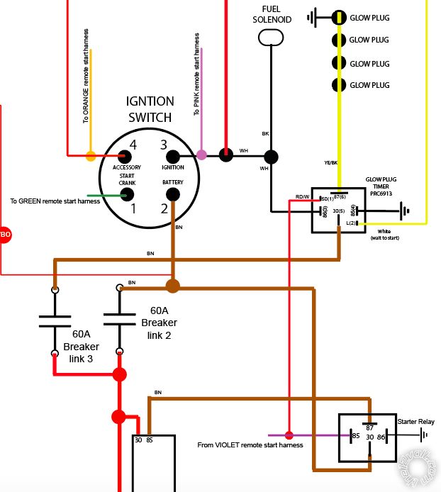
OK walked through the info provided and here is the updated diagram incorporating the remote start harness (excluding 12VDC to the harness- only ignition and starter connections)
in a nutshell -
No 'direct' connection from crank on ignition switch to starter relay - now runs via Viper internal relay on green + violet wires. (normal operation is crank energises starter relay, alarm active or R/S initiated - key ignition does not energise starter).
Connection to both acc orange and Run/Ign pink with remote start.
One Question: With diesels they are pretty easy to get running - short the starter to crank and ensure fuel solenoid is energised. Viper cant isolate the fuel solenoid to prevent such?
Posted By: itolond
Date Posted: December 09, 2019 at 12:07 PM
Hi Forum,
Looking to setup the viper on my Diesel.
I hear/see a lot of negative feedback regarding hooking up Wait to start signal from the glow plug timer in forums, and consider perhaps its better to simply place a 15-20 wait to start instead.
few questions:
Can start delay be programmed via the remote/s? * i did a search in the manula and could not find anything that struck me as definitive)
any options thoughts on the wait to start input?
Posted By: kreg357
Date Posted: December 09, 2019 at 6:58 PM
Going by the Viper 5806 install guide, you can only get
15, 30 or 45 seconds Diesel Start Delay with the remotes.
This is in Menu 3 Feature 9 Options 2, 3 and 4.
If you had a BitWriter you could select anything between
1 and 90 seconds as the Diesel Delay. This is in the
BitWriter only table Item 9.
-------------
Soldering is fun!
15, 30 or 45 seconds Diesel Start Delay with the remotes.
This is in Menu 3 Feature 9 Options 2, 3 and 4.
If you had a BitWriter you could select anything between
1 and 90 seconds as the Diesel Delay. This is in the
BitWriter only table Item 9.
-------------
Soldering is fun!