Avital 5103l Remote Start, 1985 Chevrolet Monte Carlo
Printed From: the12volt.com
Forum Name: Car Security and Convenience
Forum Discription: Car Alarms, Keyless Entries, Remote Starters, Immobilizer Bypasses, Sensors, Door Locks, Window Modules, Heated Mirrors, Heated Seats, etc.
URL: https://www.the12volt.com/installbay/forum_posts.asp?tid=145950
Printed Date: May 06, 2026 at 6:13 PM
Topic: Avital 5103l Remote Start, 1985 Chevrolet Monte Carlo
Posted By: infektid
Subject: Avital 5103l Remote Start, 1985 Chevrolet Monte Carlo
Date Posted: January 17, 2020 at 6:21 PM
well here goes folks. avital alarm 5103L remote start questions- i have an easy car . an 85 monte carlo ss . the wiring guide is not all that helpful to me. in the section for the 10 pin heavy gauge connector. is where i am kind of stumped at .( shade tree electrician not pro) .what wires get cut that go to the key and the starter. https://www.the12volt.com/installbay/alarmdetail/550.html this should help here for visuals.
i see its basically the same as this ( https://www.directeddealers.com/manuals/IG/Viper/QRN5X05%202015-06%20web.pdf) as far as what pins go where but does this thing have built in relays onboard or it still needs a relay of some sort for remote starting? far as i can deduce is it uses one relay as it says relay in and out but to this old man, its not clearly written. and the door locks also. whats the correct way to wire that also. (https://www.crutchfield.com/S-YYkPbph8NLR/p_607451M/XpressKit-451M.html) the rest i can get .
i know i am all over the world with these questions but 1) how to wire up the remote start section and 2) door lock connections. any help is appreciated. i just cant see paying( i will if i have too) around 130-200 for connecting this and i have the alarm.. thnx again folks. move to the right area if this is not it please. i do know how to use a multi meter.
Replies:
Posted By: kreg357
Date Posted: January 17, 2020 at 8:55 PM
I found an Avital 5103 Install Guide in the downloads section. It might be an old one, it's not 5103L, just 5103. You mentioned that the 5105 install guide was close to your system. Either way, go by the wire color and description and not the specific plug and pin number as they probably changed. Your 5103L has built-in relays, so you won't need any external relays for the ignition wires.
Here is the 5103 main ignition harness and it's vehicle connections :
H/1 PURPLE STARTER OUTPUT (STARTER SIDE) Purple
H/2 GREEN STARTER INPUT (KEY SIDE) Purple
H/3 RED (+) (30A) HIGH CURRENT 12V INPUT Red
H/4 ORANGE OUTPUT TO ACCESSORY Orange
H/5 PINK OUTPUT TO PRIMARY IGNITION Pink
H/6 RED (+) (30A) HIGH CURRENT 12V INPUT Red
H/7 PINK/WHITE OUTPUT TO SECOND IGNITION not used
H/8 RED/WHITE (+) (30A) HIGH CURRENT 12V INPUT Red
You should load balance the 5103L's +12V constant fused input wires between all available vehicle +12V supply wires. If you want Starter Kill / Anit-Grind functions, then cut the vehicles Purple Starter wire in an accessible location and connect the 5103L's Purple and Green wires as per their marked notes.
The older 5103 has push / pull (or flip/flop) type door lock outputs while the newer 5105 has straight (-) output signals. Here is the info from the 5103 guide :
Door lock harness, 3-pin connector
1 LIGHT BLUE (-) UNLOCK (+) LOCK OUTPUT
2 EMPTY NOT USED
3 GREEN (-) LOCK (+) UNLOCK OUTPUT
Your Monte needs a (+) lock signal. If your 5103L has the older style outputs as shown above, you can connect the Light Blue wire to the Monte's Lock wire and the Green wire to the Unlock wire and it should work. I would add a 1N4001 diode with the bands towards the car in each wire connection. If your 5103L only does (-) lock outputs, get a Directed 451M Door Lock module ( ~ $10 ) and use that to make the (-) to (+) polarity conversion.
-------------
Soldering is fun!
Posted By: infektid
Date Posted: January 18, 2020 at 8:42 AM
Reading it that way for some reason made it simpler.thas the info i needed to know . I guess the stress of doing it and reading it then trying again on a hard floor makes it worse . I can get it now that I know it dosen use an external relay.( Nothing about that in th manual) so I should be up and running then . Thnx for the info and your time and for helping people on here also .
Posted By: infektid
Date Posted: January 19, 2020 at 3:08 PM
Second part of it is ..
Everything should be wired the same as what you told me right? Not trying to pop fuses and let the mask. Smoke out .. ohh ant the door lock relay is a 451m model sorry about that
Posted By: kreg357
Date Posted: January 19, 2020 at 8:29 PM
Once again, this info is only accurate if your 5103L has the same connectors and pin/wire connections as shown in the 5X05 Install Guide.
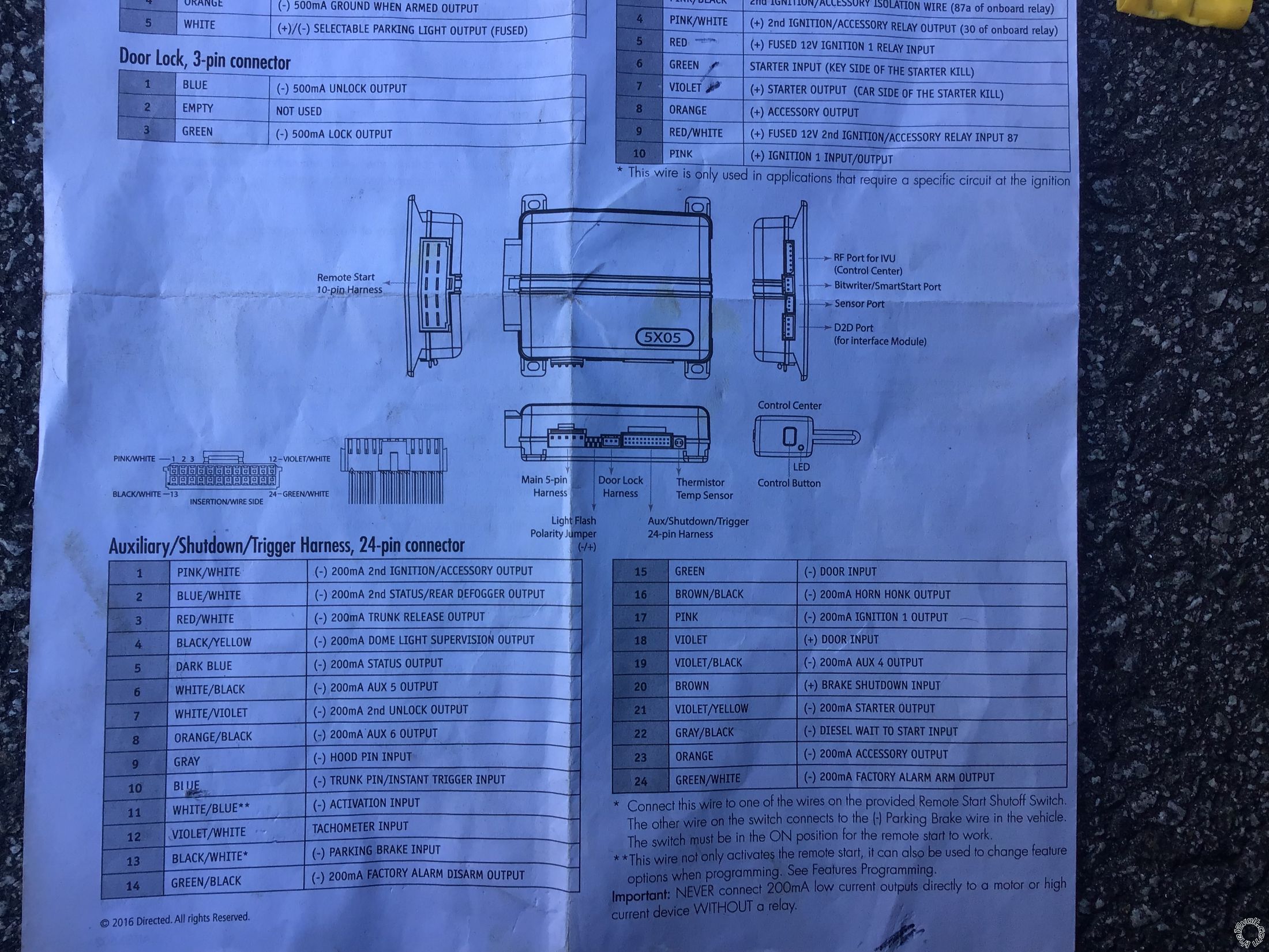
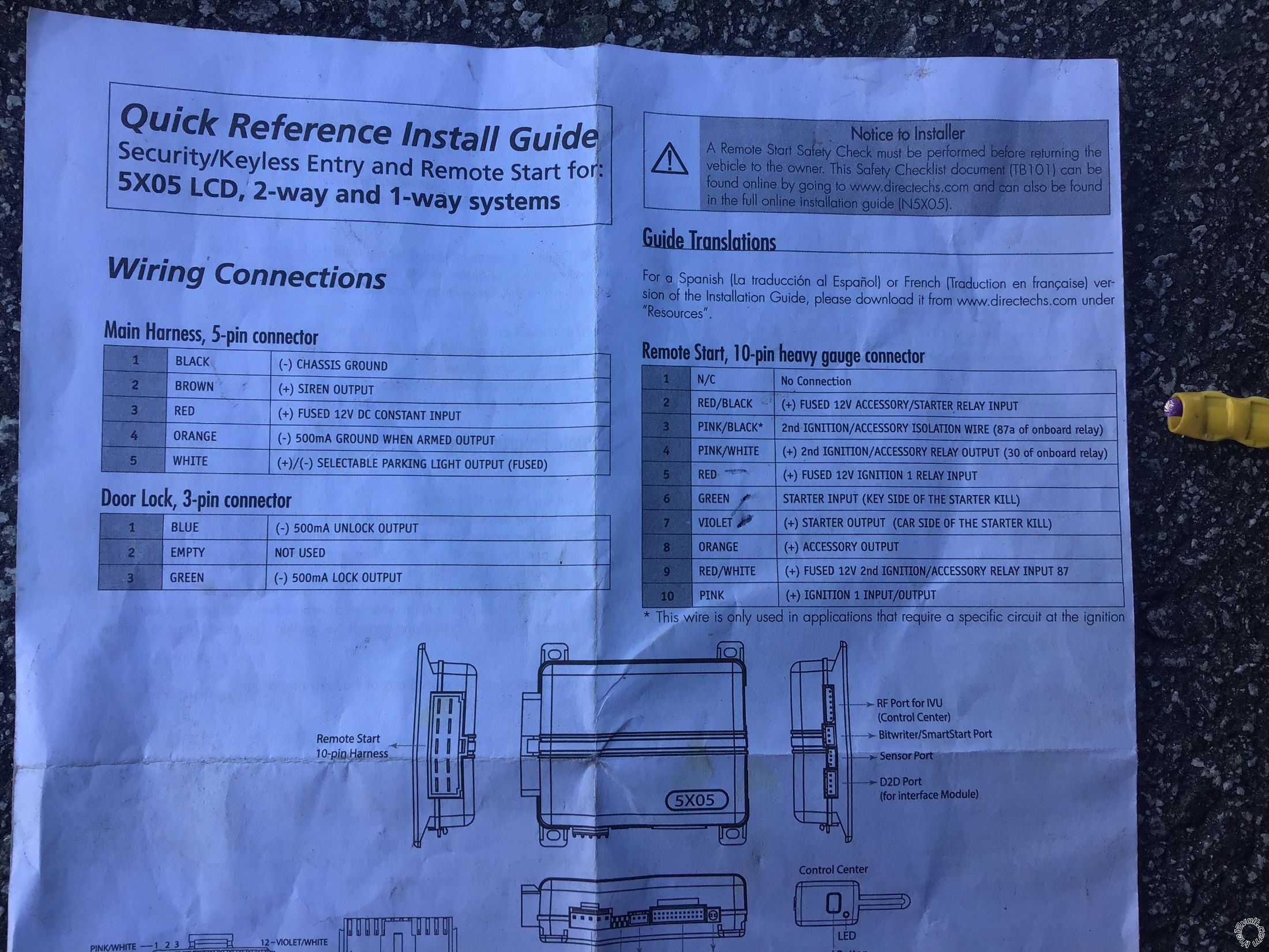
Main Harness, White 5-pin connector
1 BLACK (-) CHASSIS GROUND Chassis Ground
2 BROWN (+) SIREN OUTPUT Siren
3 RED (+) FUSED 12V DC CONSTANT INPUT +12V Constant
4 ORANGE (-) 500mA GWA Not Used
5 WHITE (+)/(-) PARKING LIGHT *Set to + Brown @ Headlight Switch
Auxiliary/Shutdown/Trigger Harness, White 24-pin connector
1 PNK/WHITE (-) 200mA IGNITION 2/ACC Not Used
2 BLUE/WHITE (-) 200mA 2ND STATUS /REAR DEFOG Not Used
3 RED/WHITE (-) 200mA TRUNK RELEASE OUTPUT Black(+) @ Trunk Switch Must use relay to convert (-) to (+)
https://www.wiresheet.com/v3/diagrams200/231%20-%20Positive%20Pulse%20Trunk%20Release%20Circuit.pdf
4 BLACK/YELLOW (-) 200mA DOME LIGHT OUTPUT Not Used
5 DARK BLUE (-) 200mA STATUS OUTPUTNot Used
6 WHITE/BLACK (-) 200mA AUX 5 OUTPUT Not Used
7 WHITE/VIOLET (-) 200mA 2nd UNLOCK OUTPUT Not Used
8 ORANGE/BLACK (-) 200mA AUX 6 OUTPUT Not Used
9 GRAY (-) HOOD PIN INPUT Kit supplied Hood Pin
10 BLUE (-) TRUNK PIN/INSTANT TRIGGER INPUT No info found. Use the Trunk Light, might need a relay
11 WHITE/BLUE (-) REMOTE START ACTIVATION INPUT Not Used
12 VIOLET/WHITE TACHOMETER INPUT White @ Coil
13 BLACK/WHITE* (-) PARKING BRAKE Chassis Ground if Auto Trans
14 GREEN/BLACK (-) 200mA FACTORY ALARM DISARM Not Used
15 GREEN (-) DOOR INPUT White = Drivers Door Pin *
16 BROWN/BLACK (-) 200mA HORN HONK OUTPUT Black at Steering Column
17 PINK (-) 200mA IGNITION 1 OUTPUT Not Used
18 VIOLET (+) DOOR INPUT Not Used
19 VIOLET/BLACK (-) 200mA AUX 4 OUTPUT Not Used
20 BROWN (+) BRAKE SHUTDOWN INPUT White @ Brake Pedal Switch
21 VIOLET/YELLOW (-) 200mA STARTER OUTPUT Not Used
22 GRAY/BLACK (-) DIESEL WTS (WAIT-TO-START) INPUT Not Used
23 ORANGE (-) 200mA ACCESSORY OUTPUT Not Used
24 GREEN/WHITE (-) 200mA FACTORY ALARM ARM OUTPUT Not Used
* This is only the Drivers Door Pin. I have no info on the Passengers Door Pin wire. For proper alarm coverage you should use both door pin wires and diode isolate them.
Remote Start, White 10-pin heavy gauge connector
1 No Connection
2 RED/BLACK (+) FUSED 12V ACCESSORY/STARTER INPUT +12V Constant
3 PINK/BLACK* (+) IGNITION 2 pin 87aNot Used
4 PINK/WHITE (+) IGNITION 2 / ACCESSORY2 Brown Program to ACC2
5 RED (+) FUSED 12V IGNITION 1 INPUT +12V Constant
6 GREEN (+) STARTER INPUT (KEY SIDE) Purple **
7 VIOLET (+) STARTER OUTPUT (CAR SIDE) Purple ***
8 ORANGE (+) ACCESSORY OUTPUT Orange
9 RED/WHITE (+) FUSED 12V IGNITION 2 +12V Constant
10 PINK (+) IGNITION 1 INPUT/OUTPUT Pink
** If you want Starter Kill and Anti-Grind, cut the Monte's Purple wire and make the connections shown using both Green and Violet wires.
*** If you don't want Starter Kill and Anti-Grind, don't cut the Mointe's Purple Starter wire, don't use the 5103's Green wire and connect only the 5103's Violet wire to the uncut Purple wire.
Door Lock, White 3-pin connector
1 BLUE (-) 500mA UNLOCK OUTPUT To 451M module
2 EMPTY NOT USED
3 GREEN (-) 500mA LOCK OUTPUT To 451M module
If I remember correctly, the SS version had a LG4 305 CI engine with a Rochester carburetor with around 180 HP. The big question is if the gas pedal needs to be depressed and released to set the choke prior to starting the engine.
-------------
Soldering is fun!
Posted By: infektid
Date Posted: January 20, 2020 at 6:45 AM
You are so awesome dude!! .. that engine has been gone a long time ago. Its. Dart engine now .406 all forged internally 215cc heads headers ,blah blah bla... I should send you some money or something man !! 👍👍. I just posted it because I found the manual ,my son had it somewhere.. thnx again !
Posted By: self_tawt_tech
Date Posted: September 15, 2020 at 2:38 PM
infektid, hope the install went smoothly!
Hello to you both. Hoping to piggyback your conversation and not create a redundant thread. I am adding a 5706V to a 1981 Monte Carlo. Both alarms appear to share near identical wiring. I will not connect the remote start portion of the 5706v at this time. Will be adding EFI next year, safer than a carburetor based install. My addition questions are:
1. My inspection of the door trigger cable in car shows it is a +12v (red led on my test light when door opens). Am I reading my light wrong or should the -violet be used vs +green (from 24 pin)?
2. Also using 451m module. No diodes needed via use of module? If still required, on which wires, between what modules/units/vehicle, which direction will cathode/anode be?
3. I do want the starter-kill function when alarm is armed. Aside from connecting green & violet wires (from 10 pin) to vehicle, what other wires from this harness would I need for this function?
Thanks in advance!
Posted By: self_tawt_tech
Date Posted: September 15, 2020 at 4:38 PM
Note: My alarm is a Viper 5706v. Directed makes Avital, Viper among other brand lines.
4. The alarms green & blue starter kill wires are part of an onboard relay? Or would I need to add a relay? If I understand the manual correctly, there is an onboard relay.
Thanks again.
Posted By: self_tawt_tech
Date Posted: September 17, 2020 at 4:20 PM
Regarding #1, I did read my light wrong. Its a negative trigger.
|