Here is some info on the U.S. version Landcruiser of 1991 through 1997 from Bulldog Security :
POWER LOCK BLUE/BLACK (TYPE B) IN DRIVERS DOOR HARNESS
POWER UNLOCK BLUE/YELLOW and BLUE/ORANGE (TYPE B) IN DRIVERS DOOR HARNESS
Don't have any info on your RKE system but you should set it for (-) Door Lock and Unlock outputs.
A direct connection to the Lock wire is all you need. For the Unlock you will need two 1N4001 diodes
and follow this diagram :
https://diagrams.marktoonen.nl/DOWNLOADS/26500_LAND-CRUISER_TOYOTA%20UNLOCK%20DIAGRAM.pdf
To locate and test the above mentioned lock wires use a Digital Multi Meter set to 20V DC. Connect the Red test lead
to +12V constant and the Black test lead to the suspect wire. Press the drivers door lock/inlock buttons to see the DMM
go to +12V.
-------------
Soldering is fun!
thanks mate for your reply really appreciated
i forgot to write some info about the car and the system
its RHD Australian model without factory alarm or key less system
i searched online a lot almost all what i found was for U.S cars
all the wires were different color/location etc
i located the lock/unlock wires as you said using the multi meter when i tried to connect them nothing happened but i didn't used any diodes it was a little bit confusing because some people worked out for them with direct connection to lock/unlock wires some got lucky with the wires before the central door control unit , but i had no luck anyway
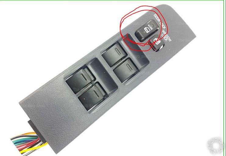
last try was to connect the wires to the main lock/unlock switch i hacked the rear cover the button has 3 wires 3.2.1 if i want to lock it 1 and 2 will contact so the car locks to unlock it 2 and 3 will connect to each other so it opens , there were my problem what to do about the 3rd wire or how to connect it , some people worked out for them with direct connection to lock/unlock wires some got lucky with the wires before the central door control unit , but i had no luck anyway
It might be easier to use relays controlled by the aftermarket RKE system to duplicate what the central locking switch does.
You would need two 30/40 Amp SPDT relays and the 5 wire harness.
Lock Relay :
Relay Pin 85 to RKE (-) Lock output
Relay Pin 86 to +12V constant
Relay Pin 30 to central locking switch Pin 2
Relay Pin 87 to central locking switch Pin 1
Unlock Relay :
Relay Pin 85 to RKE (-) Unlock output
Relay Pin 86 to +12V constant
Relay Pin 30 to central locking switch Pin 2
Relay Pin 87 to central locking switch Pin 3
All that is left is to figure out which two wires from the RKE system supply a (-) output with the remotes lock/unlock commands.
-------------
Soldering is fun!