Hello everybody, this forum has been very helpful to me during the process of installing an alarm system in my 1991 Toyota cressida, its wired up and panels are still off because i have not been able to make the remote start work. the wiring colors provided by the12volt may be wrong or maybe i am wrong and the listed colors are correct. I can provide diagrams if needed to make it easier on everyone, just let me know which ones to provide pictures of. i have attached my remote start 10 pin wiring set up to also make things easier. my problem is the remote start does not work. when activated with the remote I get 7 flashes from the parking lights and no start or crank. When i first connected the remote start wiring the car would not shut off with the key removed unless i removed the 10pin remote start connector, narrowed it down to the pink/white wire, as soon as it is pulled out the engine shuts off.
1. NC - No connection
2. RED / black(+)Fused 12v Accessory (ST1 WHITE/BLACK WIRE SAME AS STARTER INPUT) -NO VOLTAGE ON THIS WIRE
3. Pink/black(+)Flex relay key side (AM2 WHITE/RED WIRE) -12V CONSTANT
4. Pink/white(+)Igntition 2/Flex relay output - (AM2 BLACK/RED WIRE)
5. Red(+)Fused ignition 1 input - (AM1 WHITE WIRE) -12V CONSTANT
6. Green(+)Starter input (KEY SIDE ST1 WHITE/BLACK)
7. Violet(+)Starter output (STARTER SIDE ST1 WHITE/BLACK)
8. Orange(+)Accessory output (ACC. BLU/RED WIRE) -0V KEY OFF, 12V IN ACC AND KEY ON
9. RED/white(+)Fused 12v ignition 2/flex relay input (AM2 WHITE/RED) - 0V KEY OFF, 0V KEY ACC, 12V WITH KEY ON
10. Pink (+)Ignition 1 input/output (IG1 BLACK/YELLOW) - 0V KEY OFF, 0V KEY ACC, 12V KEY ON
Seven flashes? Sounds like you are still in Manual Transmission Mode. I'm guessing that your Cressida is an Auto Trans car so...
1. Program the Viper Menu 3, Item 1 to Auto Trans
2. Connect the Viper Neutral Safety wire to Chassis Ground ( or Parking Brake if you wish )
3. Disconnect the Pink/Black wire from +12V constant. It is not used.
Going by Bulldog Info here is what the connections should be :
1. NC - No connection
2. RED / black(+)Fused 12v Accessory WHITE/Red WIRE 12V constant
3. Pink/black(+)Flex relay key side
4. Pink/white(+)Ignition 2/Flex relay output - (AM2 BLACK/RED WIRE)
5. Red(+)Fused ignition 1 input - (AM1 WHITE WIRE) -12V CONSTANT
6. Green(+)Starter input (KEY SIDE ST1 BLACK/White)
7. Violet(+)Starter output (STARTER SIDE ST1 BLACK/White)
8. Orange(+)Accessory output (ACC. BLU/RED WIRE)
9. RED/white(+)Fused 12v ignition 2 WHITE/RED) 12V constant
10. Pink (+)Ignition 1 input/output (IG1 BLACK/YELLOW)
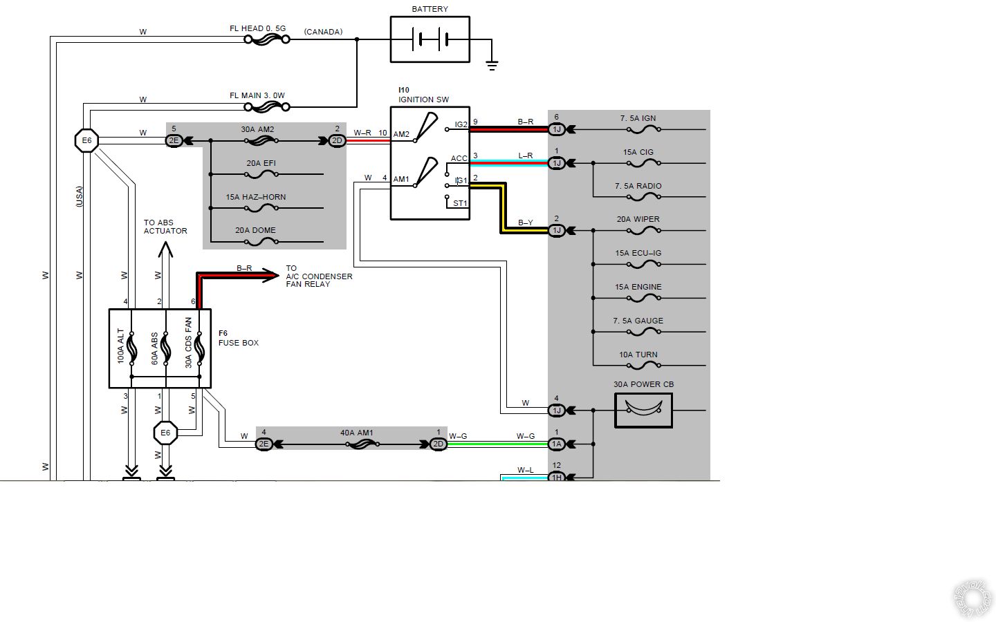
Bulldog Info :
12 VOLT CONSTANT
WHITE (+) and WHITE/RED (+) @ IGNITION SWITCH HARNESS
STARTER BLACK/WHITE (+) @ IGNITION SWITCH HARNESS
STARTER 2 N/A
IGNITION 1 BLACK/YELLOW (+) @ IGNITION SWITCH HARNESS
IGNITION 2 BLACK/RED (+) @ IGNITION SWITCH HARNESS
IGNITION 3 N/A
ACCESSORY/HEATER BLOWER 1 BLUE/RED (+) @ IGNITION SWITCH HARNESS
-------------
Soldering is fun!
Thank you very much!!! The wiring you provided was correct. Only took me a few minutes and had it working like a charm!
Great! Happy to hear it's all working. That 2 page "Install Guide" that comes with the 5706 doesn't really give detailed info. Enjoy.
-------------
Soldering is fun!