2005 Honda Civic, Remote Start Install
Printed From: the12volt.comForum Name: Car Security and Convenience
Forum Discription: Car Alarms, Keyless Entries, Remote Starters, Immobilizer Bypasses, Sensors, Door Locks, Window Modules, Heated Mirrors, Heated Seats, etc.
URL: https://www.the12volt.com/installbay/forum_posts.asp?tid=146133
Printed Date: May 07, 2026 at 6:35 PM
Topic: 2005 Honda Civic, Remote Start Install
Posted By: kinggeorge3287
Subject: 2005 Honda Civic, Remote Start Install
Date Posted: April 09, 2020 at 5:58 PM
Hi,
I am trying to install a remote start on a 2005 honda civic LX. I solely doing this for the purpose of Experience and learning. I had an old remote start kit that I purchased from Amazon in 2012 for $22. the model number is (DEI Ready Remote 24921 Car Auto Remote Start System).
From the Honda wiring diagram I see, there is 2 Accessory/heater Blower. How would I wire this? Can I just use on the of the accessory wire or do I need to use both accessories? Do I need to use a relay?
any help in understanding this is much appreciated.
thank you
George
Replies:
Posted By: kreg357
Date Posted: April 10, 2020 at 7:17 AM
Hi George! Welcome to the 12Volt.
The Ready Remote has been out of production for a while. It is a decent unit, but with some limitations.
Here is a link to the install guide : file:///C:/Remotes2/ReadyRemote/N24921%202011%2011%20web.pdf
I think there is a way to get the Directed Wire Guide for your car from DEI using the UPC code from the 24921 package.
The 24921 can handle your Civics two Accessory wires, no extra relays required. You can use the thick Pink/White wire at H2/5 for ACC2 if you set the units programming properly. See Feature 6, Option 2.
You will also want to program the unit to Continous Parking Light output, Feature 3, Option 2, and Engine Checking to Tach, Feature 1 Option 4. I would also set the unit for 2 pulse activation, Feature 5 Option 2, to prevent unwanted start-ups.
The main issue you will have with this unit is it's lack of Remote Keyless Entry functions. If I remember correctly, the Civics Factory Remote Keyless Entry FOB's will not work while the engine is remote started.
There is a Parking Liught polarity jumper on the side of the brain that you will want to set according to which vehicle Parking Light wire you choose to use, (+) or (-).
This unit is only for auto transmission vehicles. As such, H3/1 Neutral Safety can be connected to chassis ground due to the Civics built in safety systems.
You will need a bypass module to handle the cars transponder chip based engine immobilizer system, There are many to choose from. Some that come to mind are the Fortin Honda SL-3 and Key-Override-ALL bypass modules.
Bypass module Install guide links below :
https://cdn02.fortin.ca/download/27521/honda-sl3.revzc.pdf
https://cdn02.fortin.ca/download/41731/honda_civic_0105.pdf
My suggestion would be to create a list of your proposed wire connections and post it for member review.
-------------
Soldering is fun!
Posted By: lectricguy
Date Posted: April 10, 2020 at 7:41 AM
Your ignition connections are:
12 VOLT CONSTANT WHITE (+) @ IGNITION SWITCH HARNESS
STARTER BLACK/WHITE (+) @ IGNITION SWITCH HARNESS
IGNITION 1 BLACK/YELLOW (+) @ IGNITION SWITCH HARNESS
ACCESSORY/HEATER BLOWER 1 BLACK/RED (+) @ IGNITION SWITCH HARNESS
ACCESSORY/HEATER BLOWER 2 WHITE/RED (+) @ IGNITION SWITCH HARNESS
First off, Accessory 2 for this vehicle powers the radio, accessory outlets, and a few other non-essential items in the car. If
you do not connect it, the radio will remain off during remote start, and activate when you get in the car and perform the key takeover (i.e., turn the key, press the brake pedal).
If you want to connect it, the car will operate exactly as it does when you normally turn the key--during the remote start process, with all accessories running.
Either approach is fine, your choice.
If you want to hook up the second Accessory:
As far as Ready Remote, there are 2 versions of Ready Remote 24921; an older version (individual heavy gauge ignition wires, each plugged into the brain separately).
The link for the manual for a similar model is on this site: https://www.the12volt.com/installbay/downloads.asp?srch=all&term=ready+remote+24923
This older model has 2 ignition wires and 1 accessory wire. The second ignition is not programmable. So if you have this older model, please refer to the section on wiring 2 accessories; it will require 2 relays to drive both accessory wires.
The newer model has 6 heavy gauge wires in a single 6 pin connector(actually this model is a re-banded Avital 4105). The newer model's second ignition wire is programmable, so you would hook up the second accessory in the vehicle to the second ignition wire on the remote start and reprogram it to operate to function as an accessory output.
I'll defer to Kreg's excellent post for additional details with the newer version.
-------------
Lectric Guy
Posted By: kinggeorge3287
Date Posted: April 12, 2020 at 11:54 PM
Hi all,
Thank you all for the great information.
1. I do have the older model ( 2 ignition wires and 1 accessory wire). So I am not going to use the Second Accessory as it is not needed.
2. My car has an aftermarket Security system Previsely installed Hornet 700T. Can I keep this system in place while installing the remote start? Can I integrate this somehow? Is there a wire that needs to be connected between the two?
I have ordered (Directed DEI 556UW Universal Remote Start Bypass Module )
Primary Harness H1 8-pin connector Honda 2005 LX
H1/1 - Blue ............................................Blue ( on the 556u Immobilizer)
H1/2- violet/white ...........................................Blue(AC)
H1/3 - Brown ............................................White/Black
H1/4 - Gray ............................................HoodPin
H1/5 - Black ..........................................Ground
H1/6 - White/Blue (RemotStart Activation Input)...............???
H1/7 - LT. Green/Black (Factory Alarm Disarm/RAP Cancellation)..???
H1/8 - White ............................................Blue(-) or White (+)??
Relay Wires 6-connectors
A - Violet............................................... Black/White
B - Red.................................................. White
C-Orange................................................. Black/Red
D-Pink................................................... Black/Yellow
E-Red.................................................... White
F- Pink/White............................................ N/A ( IGN2)
What do you all think of this?
Thank you
George
Posted By: lectricguy
Date Posted: April 13, 2020 at 8:46 AM
The Ready Remote 24921 is an older and very basic remote start. There are very few features that you can configure on this unit, and limited functionality. It would be easier, cleaner, and allow for more support if needed, to use an upgraded brand of Alarm/Remote start combination in this type of application. You will also get increased remote range from a newer system (I believe the Ready remote 24921 was only around 500 ft, Hornet 700T has an internal antenna, so that distance is limited as well). Audiovox, Compustar, and Directed's Viper/Python/Avital all have versions that will improve on what you have and provide more range.
That being said, you can add the Ready Remote 24921 to your car. Keep in mind that limitations come with the basic unit and the combinations you are trying to put together.
As far as the alarm combination, the Hornet 700T monitors the ignition wire in the car. This will need to be opened during remote start, which will keep your alarm from going off due to the ignition activating. This can be done with your unit, however it will require 2 diodes and a relay.
The diodes can be general purpose, such as 1N4001. The relay would be 5 pin general purpose automotive relay (refer to the relay section of this site). You would connect the bands of both diodes together and also to the H1/1 Blue wire of the 24921. The other (non-banded) ends of the diodes create 2 separate Ground When Running connections; one to connect to the 555UW Ground when Running input, and the other will go to the relay to work around the alarm's ignition connection during remote start. The relay connections will be:
86: +12V
85: the unbanded Ground when Running signal described above
Cut the Hornet's Yellow H1/9 Alarm ignition wire.
Relay Pin 30: one side of the cut Hornet ignition wire
Relay Pin 87A: Other side of the cut Hornet ignition wire
Relay Pin 87: Not connected
Do you want to control the Remote Start from the Hornet Alarm? If so, you would use the Red/White Channel 2 output from the Hornet alarm to connect to the
H1/6 - White/Blue (Remote Start Activation Input). I believe that the older 24921 requires 2 pulses to activate, so you would activate the channel 2 output 2 times to activate the remote start. Even if this Activation input is hooked up, the Ready Remote 24921 remotes will still remain active and can be used to enable the remote start if desired.
The Ready Remote 24921 only has a negative parking light output. So for H1/8 White output from the Ready Remote unit, using the PARKING LIGHTS ( - )BLUE (-)@ HEADLIGHT SWITCH UNDER STEERING COLUMN COVER will be simpler, as it won't require an additional relay.
H1/7 - LT. Green/Black (Factory Alarm Disarm) is used to disable a factory alarm (Which you do not have), so you would not use this.
Be careful in connecting to colors in your Honda without verifying. Get access to a DC voltmeter and test each wire before hooking up to it.
Primary Harness H1 8-pin connector Honda 2005 LX
H1/1 - Blue ............................................Ground When Running (To the banded end of 2 diodes; one unbanded end to the 556uw Immobilizer Bypass, the other unbanded end to a relay, see above)
H1/2- violet/white ...........................................Tach:Blue(AC) @ TACH TEST CONNECTOR (2 PIN CONNECTOR ON THE PASSENGER SIDE OF THE BATTERY).
H1/3 - Brown ............................................Brake (+): White/Black @ SWITCH ABOVE BRAKE PEDAL
H1/4 - Gray ............................................HoodPin
H1/5 - Black ..........................................Ground
H1/6 - White/Blue (Remote Start Activation Input)...............Activation Input: To Hornet Red/White Ch 2 output
H1/7 - LT. Green/Black (Factory Alarm Disarm/RAP Cancellation)..Not Used
H1/8 - White ............................................Headlights(-):Blue(-) @ HEADLIGHT SWITCH UNDER STEERING COLUMN COVER
Relay Wires 6-connectors
A - Violet............................................... Starter: Black/White @ IGNITION SWITCH HARNESS
B - Red.................................................. 12V: White @ IGNITION SWITCH HARNESS
C-Orange................................................. Accy 1:Black/Red @ IGNITION SWITCH HARNESS
D-Pink................................................... Ign1:Black/Yellow @ IGNITION SWITCH HARNESS
E-Red.................................................... 12V:White @ IGNITION SWITCH HARNESS
F- Pink/White............................................ N/A (IGN2)
-------------
Lectric Guy
Posted By: kinggeorge3287
Date Posted: April 13, 2020 at 11:44 PM
Hi, Thank you for all the great information. I am waiting for all the supplies to come in to get started.
One question I installed a "Trunk Release Solenoid" a while back. Can you integrate this with the system? where the remote can pop the trunk. I know there is no dedicated button on the remote.
thank you again
George
One question I installed a "Trunk Release Solenoid" a while back. Can you integrate this with the system? where the remote can pop the trunk. I know there is no dedicated button on the remote.
thank you again
George
Posted By: lectricguy
Date Posted: April 14, 2020 at 3:11 PM
This is where limitations of the Hornet-Ready Remote combination start to come in. The Hornet 700T has one Red/White output for an accessory.
You can use this to control the Remote Start, or as a Trunk release. If you use it for the trunk release, this would require you to carry a separate remote for the remote start. Not ideal, but not terrible either.
The advantage is that the Ready Remote fob has a little longer range than the Hornet fob. The disadvantage is that you will be carrying 2 remotes; one for alarm/keyless entry and another for remote start.
For trunk release, you would need a relay to drive the trunk solenoid. Assuming that you are switching 12V to the trunk solenoid and the other solenoid lead is grounded in the trunk area, You would hook up:
Relay Pins 30 & 36: +12V Constant
Relay Pin 35: Hornet H1/12 Red/White
Relay Pin 87A: Not connected
Relay Pin 87: solenoid + lead
There are also other ways to pop the trunk solenoid with the hornet fob and/or with the original fobs. This would use a module like the PAC TR-7 and a relay. You would program the TR-7 to generate an output after sensing 3 lock motor pulses within a timeframe, like 6 seconds. The output would then drive a relay to pop the trunk solenoid.
Hope this helps.
-------------
Lectric Guy
Posted By: kinggeorge3287
Date Posted: April 15, 2020 at 11:07 PM
Hi,
I am very much interested in using the PAC TR-7 with hornet. How would I go about the wiring? I was reading the user manual of pac tr-7. any help is welcome.
thank you for all the help
George
I am very much interested in using the PAC TR-7 with hornet. How would I go about the wiring? I was reading the user manual of pac tr-7. any help is welcome.
thank you for all the help
George
Posted By: lectricguy
Date Posted: April 16, 2020 at 11:21 AM
George-
The PAC TR-7 would connect as follows:
Red to Fused +12V constant
Black to Ground
Green input to the Driver's door unlock motor (UNLOCK MOTOR|YELLOW /GREEN|back of the fusebox, Top left plug or Driver's Kick)
-This wire will remain at ground, pulses to 12V when you unlock with the door switch or the remote.
White (-) output to relay pin 85
(Numbering typo from above post----numbers should be should be 85 & 86, not 35 & 36)
Relay connections:
Relay Pins 30 & 86: +12V Fused Constant
Relay Pin 85: Hornet H1/12 Red/White (and/or TR7 White lead)
Relay Pin 87A: Not connected
Relay Pin 87: solenoid + lead
A figure of this would be:
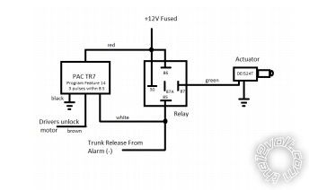
Your trunk solenoid would take the place of the actuator in the diagram. If you don't end up using the Hornet Red/White to activate the remote start, you could also hook up the alarm's Red/White output to the relay pin 85 along with the TR-7's output if you want, no issues. Then either the factory remotes or the alarm's remotes would pop the trunk. Of course, just make sure that the alarm is not armed if you use the factory remote.
For TR-7 Programming, you would use Feature #14, Set it up to could 3 (unlock) pulses in 8 seconds. There is a switch to place the TR-7 in program mode, and back to operational mode when you are done.
Programming the TR-7 can be frustrating, I recommend using a push button switch to program it on the bench before installing. If you make a mistake, just power off and on and restart the programming.
Be patient and follow the PAC guide and you should be OK.
-------------
Lectric Guy
The PAC TR-7 would connect as follows:
Red to Fused +12V constant
Black to Ground
Green input to the Driver's door unlock motor (UNLOCK MOTOR|YELLOW /GREEN|back of the fusebox, Top left plug or Driver's Kick)
-This wire will remain at ground, pulses to 12V when you unlock with the door switch or the remote.
White (-) output to relay pin 85
(Numbering typo from above post----numbers should be should be 85 & 86, not 35 & 36)
Relay connections:
Relay Pins 30 & 86: +12V Fused Constant
Relay Pin 85: Hornet H1/12 Red/White (and/or TR7 White lead)
Relay Pin 87A: Not connected
Relay Pin 87: solenoid + lead
A figure of this would be:
Your trunk solenoid would take the place of the actuator in the diagram. If you don't end up using the Hornet Red/White to activate the remote start, you could also hook up the alarm's Red/White output to the relay pin 85 along with the TR-7's output if you want, no issues. Then either the factory remotes or the alarm's remotes would pop the trunk. Of course, just make sure that the alarm is not armed if you use the factory remote.
For TR-7 Programming, you would use Feature #14, Set it up to could 3 (unlock) pulses in 8 seconds. There is a switch to place the TR-7 in program mode, and back to operational mode when you are done.
Programming the TR-7 can be frustrating, I recommend using a push button switch to program it on the bench before installing. If you make a mistake, just power off and on and restart the programming.
Be patient and follow the PAC guide and you should be OK.
-------------
Lectric Guy
Posted By: kinggeorge3287
Date Posted: April 24, 2020 at 2:30 PM
Hi,
Thank you for all the help. I ordered some 5 pin relay from eBay and its taking forever to come in. I do have 4 pin 30A relay onhand, can I use that or i have to use the 5pin ?
thank you again for the help.
george
Thank you for all the help. I ordered some 5 pin relay from eBay and its taking forever to come in. I do have 4 pin 30A relay onhand, can I use that or i have to use the 5pin ?
thank you again for the help.
george
Posted By: lectricguy
Date Posted: April 24, 2020 at 4:11 PM
For the trunk release applications, either a 5 pin relay(both pin 87A & pin 87) or a 4 pin Normally Open relay (No pin 87A) will work. For the remote start Hornet alarm ignition bypass, either a 5 pin relay (both pin 87A & pin 87) or a 4 pin Normally Closed relay (No pin 87) will work.
-------------
Lectric Guy
-------------
Lectric Guy
Posted By: kinggeorge3287
Date Posted: April 25, 2020 at 11:24 PM
Hi,
I am confused about three items.
1) When Connecting the 556u Immobilizer, I am using three wires:
Red............12v constant
black..........chassis ground
blue...........(To the banded end of 2 diodes; one unbanded end to the 556u Immobilizer Bypass) ? is this correct?
2)When Saying:
"Cut the Hornet's Yellow H1/9 Alarm ignition wire.
Relay Pin 30: one side of the cut Hornet ignition wire
Relay Pin 87A: Other side of the cut Hornet ignition wire"
Which relay pin connects to which side of the ignition wire? does pin 30 go on the hornet side or 87a on hornet side? or another way around?
3)If I control the Remote Start from the Hornet Alarm
"H1/6 - White/Blue (Remote Start Activation Input)...............Activation Input: To Hornet Red/White Ch 2 output"
How do I connect the PAC tr7? Does tr7 also connect to Hornet Red/white wire?
Also, I programed the TR-7 for Feature #14, Set it up to 3 (unlock) pulses in 6 seconds. My question is If the hornet H1/12 Red/white is factory set to 2(unlock) pulses in 3 seconds, won't the car start every time I try to pop the trunk.
thank you again
George
Posted By: lectricguy
Date Posted: April 26, 2020 at 8:29 AM
1.) With 2 diodes, the banded ends connect together to for a "Y" with 2 diodes, and this point also connects to Ground When Running from your remote start. For the other (Unbanded) ends of the diode (each side of the "Y"), one connects to the '556U blue wire, and the other connects to pin 85 of the relay to open the alarm's ignition wire during remote start.
2.) For the relay pins 30 and 87A, they are acting as a switch to open the Hornet's ignition wire input. There is no polarity, either relay pin can be used on either side of the Hornet's ignition wire.
3.) Again, this is a limitation for your set up.
You can control the remote start from the Hornet fob (Using the Red/White output of the Hornet to connect to White/Blue of the Ready Remote). If you choose to do this, you would use the TR-7 and the Hornet to open the trunk (after 3 unlock pulses) using the TR-7 to sense 3 unlock pulses in 6 seconds. This will also allow factory fobs to control the trunk solenoid.
If you choose to use the Hornet Fob only to control the alarm, and the Ready Remote fob to control remote start, you could control the trunk solenoid with both the TR-7 (with unlock pulses) AND the Hornet Red/White. The drawing from my previous post shows how this is hooked up. In this case, you would only need the TR-7 if you want the factory fobs to control the trunk solenoid.
-------------
Lectric Guy
Posted By: kinggeorge3287
Date Posted: April 26, 2020 at 12:43 PM
lectricguy wrote:Hi,
3.) Again, this is a limitation for your set up.
You can control the remote start from the Hornet fob (Using the Red/White output of the Hornet to connect to White/Blue of the Ready Remote). If you choose to do this, you would use the TR-7 and the Hornet to open the trunk (after 3 unlock pulses) using the TR-7 to sense 3 unlock pulses in 6 seconds. This will also allow factory fobs to control the trunk solenoid.
If you choose to use the Hornet Fob only to control the alarm, and the Ready Remote fob to control remote start, you could control the trunk solenoid with both the TR-7 (with unlock pulses) AND the Hornet Red/White. The drawing from my previous post shows how this is hooked up. In this case, you would only need the TR-7 if you want the factory fobs to control the trunk solenoid.
Thank you again for the fast reply. sorry if I am repeating the same question. I do understand what you are saying and I do understand the limitations of my setup. I am just looking for clarity.
I only have one key fob ( hondas original factory key fob). This controls the hornet. The ready remote(24921) comes with its own remote.
Can I turn on the car and pop the trunk with the original keyfob if I use TR-7?
If I connect the ready remote (H1/6 - White/Blue..........Hornet Red/White) I can't connect the TR7 White lead to the Hornet Red/White. is this correct?
thank you again
George
Posted By: lectricguy
Date Posted: April 26, 2020 at 6:57 PM
George-
Sounds like you are making progress...I'll try to answer your questions.
1.) Can I turn on the car and pop the trunk with the original keyfob if I use TR-7?
Yes. The TR-7 will be used with unlock (3 unlocks in 6 seconds) to pop the trunk. Pressing Lock twice will activate the Hornet Red/White (connected to Ready Remote White Blue). You will need to do this twice (i.e., press lock 4 times) to activate the ready remote unit, as it needs to see 2 pulses on the white/blue to activate, and this is not programmable.
If I connect the ready remote (H1/6 - White/Blue..........Hornet Red/White) I can't connect the TR7 White lead to the Hornet Red/White. is this correct?
Correct. Use Hornet Red White to activate the Ready Remote Starter by using the lock function on the OEM fob. The TR-7 will be used for trunk release with unlock on the OEM fob.
-------------
Lectric Guy
Posted By: kinggeorge3287
Date Posted: April 26, 2020 at 11:04 PM
Hi,
Thank you again for the fast reply. I am just looking for clarity again.
So, I am planning to connect the Ready Remote to the Hornet (ready remote H1/6 - White/Blue..........Hornet Red/White) Factory remote can turn the car on. I am also planning to connect the TR-7 to the hornet ( so Factory remote can pop the trunk)
In this scenario where does the white wire attach? White (-) output to relay pin 85
But then does the relay 85 pin connect to Hornet Red/White, with is connected to ready remote H1/6 - White/Blue?
Red to Fused +12V constant
Black to Ground
Green input to the Driver's door unlock motor
White (-) output to relay pin 85
Relay Pins 30 & 86: +12V Fused Constant
Relay Pin 85: Hornet H1/12 Red/White (and/or TR7 White lead)??
Relay Pin 87A: Not connected
Relay Pin 87: solenoid + lead"
thank you
George
Posted By: lectricguy
Date Posted: April 27, 2020 at 7:06 AM
George-
Since you've decided to use the factory remote to control both Remote Start and Trunk Pop, the answers to your questions are below:
In this scenario where does the white wire attach? White (-) output to relay pin 85?
ANS: I'm assuming you are referring to the output wire from TR-7. Yes, that white (-) output wire from the TR-7 connects to Pin 85 of the trunk pop relay.
But then does the relay 85 pin connect to Hornet Red/White, with is connected to ready remote H1/6 - White/Blue?
ANS: No. Only the white wire from the TR-7 connects to Pin 85 of the trunk pop relay. The Hornet Red/White only connects to the H1/6 - White/Blue (Remote Start Activation Input) of the Ready Remote remote start.
Red to Fused +12V constant
Black to Ground
Green input to the Driver's door unlock motor
Relay Pins 30 & 86: +12V Fused Constant
Relay Pin 85: TR7 White (-) output lead
Relay Pin 87A: Not connected
Relay Pin 87: solenoid + lead
-------------
Lectric Guy
Posted By: kinggeorge3287
Date Posted: May 01, 2020 at 5:46 PM
Hi, Thank you for the clarification.
I have a question. I just realized that the hornet was a starter kill relay attached. The relay splits the ignition 1 wire.
relay pin 30 .....starter key side
relay pin 87A.....starter motor side
relay pin86....... 12v ignition wire
relay pin85......orange (-)500 mA armed output (start kill relay)
on which side of the relay do I or should I connect the ready remote violet wire. The starter key side or starter motor side.
Thank you
george
Posted By: lectricguy
Date Posted: May 01, 2020 at 7:30 PM
George-
Connect the Remote Start heavy gauge starter wire to the starter motor side wire (connected to relay pin 87A).
Good Luck, I hope this helps
-------------
Lectric Guy
Connect the Remote Start heavy gauge starter wire to the starter motor side wire (connected to relay pin 87A).
Good Luck, I hope this helps
-------------
Lectric Guy
Posted By: kinggeorge3287
Date Posted: May 02, 2020 at 9:20 AM
Hi again,
I was planning to get the 12V constant power directly from the battery(pull two 10 gauge wires through the firewall and connect all the constant power to that with fuse box) , is this OK? or do I need to get the power from (the 12V: White @ IGNITION SWITCH HARNESS).
Any recommendations on this.
thank you for all the help. thank you
George
Posted By: lectricguy
Date Posted: May 02, 2020 at 10:42 AM
George-
While you can connect to the battery with your own connection, you would be fine connecting directly to the ignition for power.
12 VOLT CONSTANT WHITE (+) @ IGNITION SWITCH HARNESS
-------------
Lectric Guy
While you can connect to the battery with your own connection, you would be fine connecting directly to the ignition for power.
12 VOLT CONSTANT WHITE (+) @ IGNITION SWITCH HARNESS
-------------
Lectric Guy
Posted By: kinggeorge3287
Date Posted: May 02, 2020 at 7:02 PM
Hi,
I am almost done with the install. I am having trouble finding the Tach test connector. I believe I have located it, can someone confirm it, please.
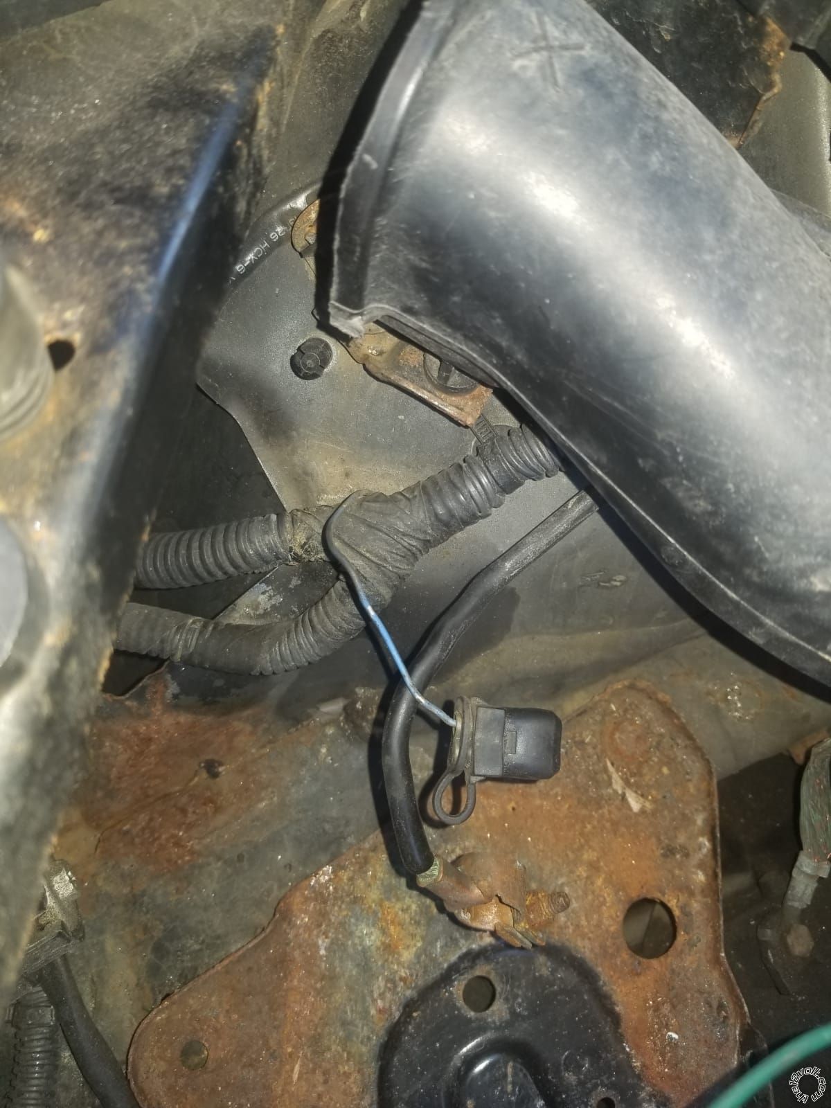
is this it? It was taped to that bundle.
Thank you
George
I am almost done with the install. I am having trouble finding the Tach test connector. I believe I have located it, can someone confirm it, please.
is this it? It was taped to that bundle.
Thank you
George
Posted By: lectricguy
Date Posted: May 03, 2020 at 7:03 AM
George-
That is the tach test connector, Blue wire. You can also test to confirm it by setting your voltmeter to 10V AC scale, probe from the wire ground and start the car. You should see a low AC voltage that increases as the engine revs.
-------------
Lectric Guy
That is the tach test connector, Blue wire. You can also test to confirm it by setting your voltmeter to 10V AC scale, probe from the wire ground and start the car. You should see a low AC voltage that increases as the engine revs.
-------------
Lectric Guy
Posted By: kinggeorge3287
Date Posted: May 04, 2020 at 7:29 PM
HI,
So, I Installed everything.
The remote start works with the ready remote( not the factory remote).
The Trunk opens with 4 unlocks (factory remote).
Honda Factory remote doesn't turn on the car. ? this may be a setting issue.
Normally when I press lock two times on the honda remote, the alarm goes off. ( first, click locks the doors and second click siren god off) Is this an issue?
another thing I noticed is, once I turn on the care with remote start and then I put the key in the cylinder and turn, the alarm goes off. I am unable to disarm the alarm with factory remote. I would have to press the brek padel or the ready remote stop button to turn off the car and then I will be able to disarm the alarm with honda remote.
any advice on solving this
Thank you for all the help.
George
Posted By: lectricguy
Date Posted: May 05, 2020 at 9:34 AM
George-
Glad to hear you've made progress.
Let's look at the remaining issues:
1.) "Honda Factory remote doesn't turn on the car. ? this may be a setting issue.
Normally when I press lock two times on the honda remote, the alarm goes off. ( first, click locks the doors and second click siren god off) Is this an issue?"
ANS: These are both the same issue. For the alarm, feature 7 (Pressing lock button 2x) is defaulted to "panic". This needs to be set to "activate Auxillary output".
2.) "another thing I noticed is, once I turn on the care with remote start and then I put the key in the cylinder and turn, the alarm goes off. I am unable to disarm the alarm with factory remote. I would have to press the brek padel or the ready remote stop button to turn off the car and then I will be able to disarm the alarm with honda remote."
ANS: Another limitation with this setup...you need to disarm the alarm before you get into the car. Since the Honda remotes won't work with the car running, you would have to disarm the alarm before you open the car door.
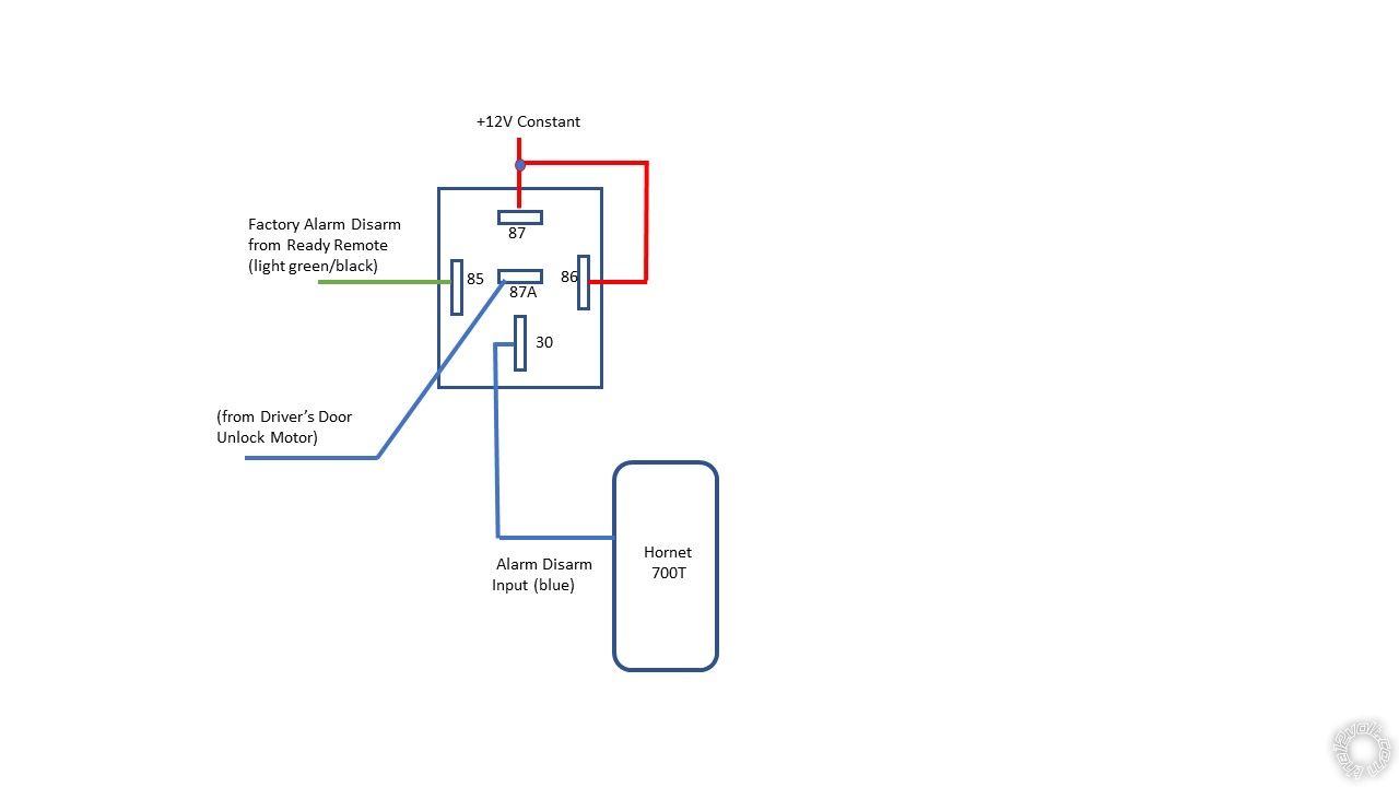
That could be accomplished with an additional relay, where the alarm would be disarmed whenever you remote start the car. Note this will disarm the alarm, but not unlock the car. You would unlock the car with the key when it is remote started.
Good Luck, I hope this helps.
-------------
Lectric Guy
Glad to hear you've made progress.
Let's look at the remaining issues:
1.) "Honda Factory remote doesn't turn on the car. ? this may be a setting issue.
Normally when I press lock two times on the honda remote, the alarm goes off. ( first, click locks the doors and second click siren god off) Is this an issue?"
ANS: These are both the same issue. For the alarm, feature 7 (Pressing lock button 2x) is defaulted to "panic". This needs to be set to "activate Auxillary output".
2.) "another thing I noticed is, once I turn on the care with remote start and then I put the key in the cylinder and turn, the alarm goes off. I am unable to disarm the alarm with factory remote. I would have to press the brek padel or the ready remote stop button to turn off the car and then I will be able to disarm the alarm with honda remote."
ANS: Another limitation with this setup...you need to disarm the alarm before you get into the car. Since the Honda remotes won't work with the car running, you would have to disarm the alarm before you open the car door.
That could be accomplished with an additional relay, where the alarm would be disarmed whenever you remote start the car. Note this will disarm the alarm, but not unlock the car. You would unlock the car with the key when it is remote started.
Good Luck, I hope this helps.
-------------
Lectric Guy