Avital 4105L Door Lock Issues, 1992 Ford Ranger
Printed From: the12volt.com
Forum Name: Car Security and Convenience
Forum Discription: Car Alarms, Keyless Entries, Remote Starters, Immobilizer Bypasses, Sensors, Door Locks, Window Modules, Heated Mirrors, Heated Seats, etc.
URL: https://www.the12volt.com/installbay/forum_posts.asp?tid=146179
Printed Date: May 07, 2026 at 1:02 AM
Topic: Avital 4105L Door Lock Issues, 1992 Ford Ranger
Posted By: jorms1
Subject: Avital 4105L Door Lock Issues, 1992 Ford Ranger
Date Posted: May 02, 2020 at 9:40 PM
I have a 1992 ford ranger xlt with a 4.0. I have installed a avital 4105L remote starter locks and security.
the remote start is working great. Door locks are not working at all. lock or unlock, I am getting signal to the wires.
Feel like I may be missing something. I get no horn or light flash either. Here is the unit wiring and what i have done.
any help would be great! Thanks!
Primary Harness
1: (-)Factory alarm disarm - did not used
2: (-)Factory rearm - did not use
3: (+)Ignition out (to alarm) - not hooked up...does it need to be?
4: (-)Activation Input - not hooked up...does it need to be?
5: (-)Ground when locked - not hooked up...does it need to be?
6: (-)Horn Output - To horn wire under column connected yellow with blue stripe
7: (-)Trunk Release Output - did not use
8: Ground - To common ground connected to body ground
9: (+/-) Light Flash - Headlight switch connected Brown
4-pin satellite harness - what is this for?
1: (-)Status Output - not hooked up...does it need to be?
2: (-) Accessory Output - not hooked up...does it need to be?
3: (-) Starter Output - not hooked up...does it need to be?
4: (-) Ignition Output - not hooked up...does it need to be?
Heavy gauge relay wiring
1: (+) High current 12v input - connected to battery
2: (+) Second ignition/Accessory circuit output - not hooked up...does it need to be?
3: (+) High current 12v input - connected through add on fuse box
4: (+) Accessory output - Ignition switch harness gray with yellow stripe
5: (+) Starter output - left of steering column pink wire
6: (+) ignition one input/output - ignition switch harness red with green stripe
Door lock harness
1: (-) Unlock output - connected to electric lock wire pink with yellow stripe
2: N/A
3: (-) Unlock output - connected to electric unlock wire pink with light green stripe
Remote start harness
1: (-)parking brake input - grounded
2: Tachometer wire - under hood near fuse box in harness with test ports tan and yellow
3: (+) Brake shutdown input - Brake wire at pedal light green
4: (-) Hood pin switch shutdown input - installed included switch and wired
5 (-) 200ma 2nd status/rear defogger output - did not use
Replies:
Posted By: kreg357
Date Posted: May 03, 2020 at 8:33 AM
You probably have the correct vehicle lock wires but for that truck they are Type C locks.
A simple direct connection of the 4105's (-) lock output will not work. You should get a Directed 451M Door Lock Module and follow the Type C install diagram.
They are available on eBay, etc for around $10.
Go to the Downloads sections and search on 451M for the Install guide.
If you had a couple of 30/40 Amp SPDT relays and an inline fuse holder you could do the it hard way and follow this diagram :
https://www.the12volt.com/relays/relaydiagram3.html
-------------
Soldering is fun!
Posted By: jorms1
Date Posted: May 03, 2020 at 9:16 AM
Thank you I will look into those and report back :)
Posted By: jorms1
Date Posted: May 03, 2020 at 9:58 PM
lots of trying with out much luck with the relays. Here is what i've done doesn't blow fuses but not really working either. Unlock makes a buzzing noise and lock makes a tick noise. lol this made me happy I used up alot of fuses before I got to this point. please help :oops:
Posted By: jorms1
Date Posted: May 04, 2020 at 5:13 PM
Does it matter were in the lock wire I connect to?
I followed the wire to the drivers side near the headlight in a harness. I have verified it is the right wire.
Posted By: kreg357
Date Posted: May 04, 2020 at 6:10 PM
Looking at your diagram, I think you want to start over.
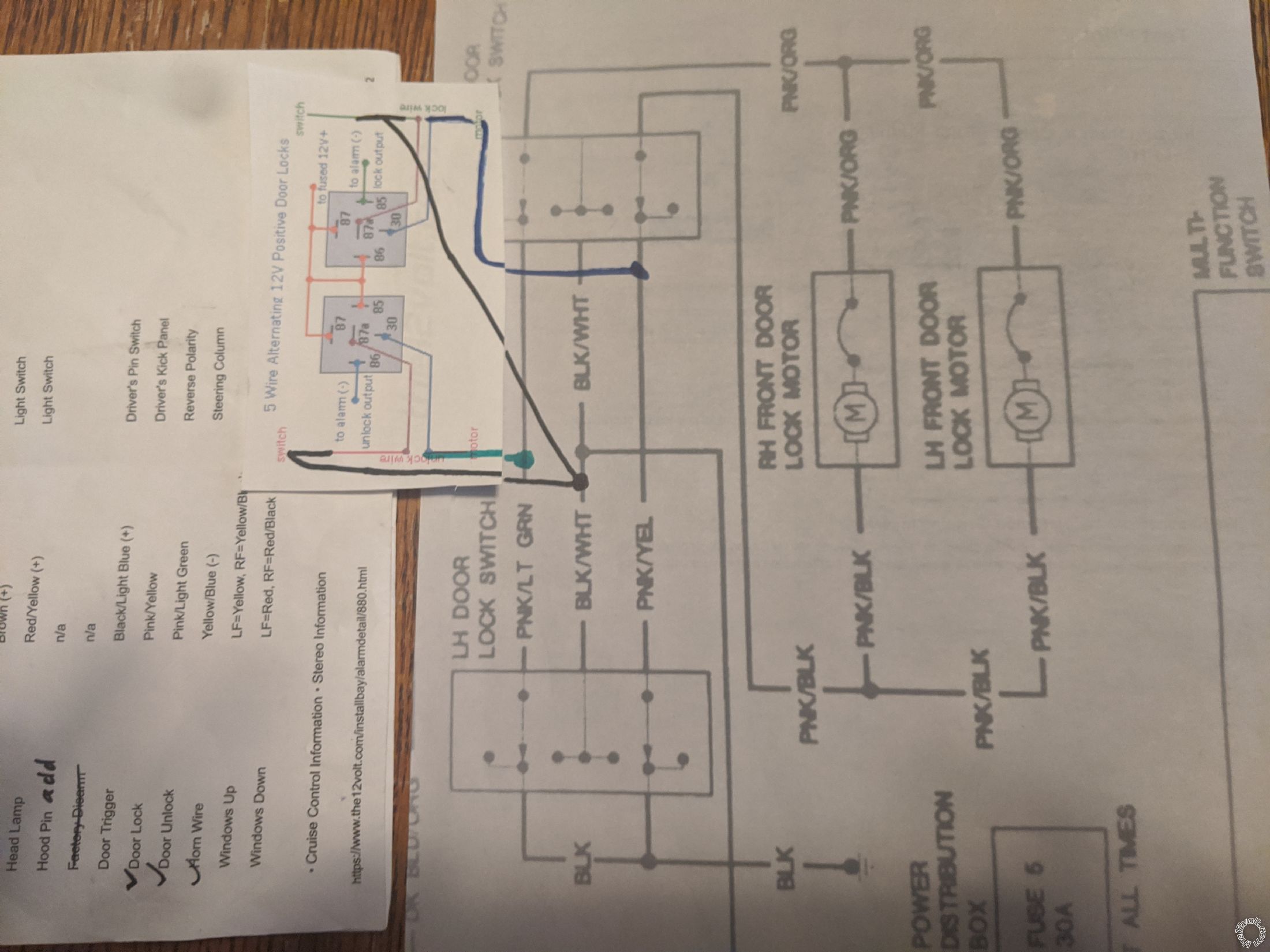
The two Ranger wires you want to cut are the Pink/Yellow and Pink/Light Green wires as mentioned above. (Not sure what you are doing with the Black/White wire but remove the connections.) Do one cut at a time and verify that the corresponding lock/unlock function stops working. This will ensure you have the correct wires. To determine which side of the cut is the motor or switch, follow this tip :
Easy way to tell which side of the cut wire is the switch and which is the motor, is to cut the wire and then press the button. If it shows 12v it is the switch side of the button you just pressed. Some times it isn't always easy to tell which end goes to the switch and which side goes to the car.
Follow this diagram for the relays, 4105 and ranger wire connections :
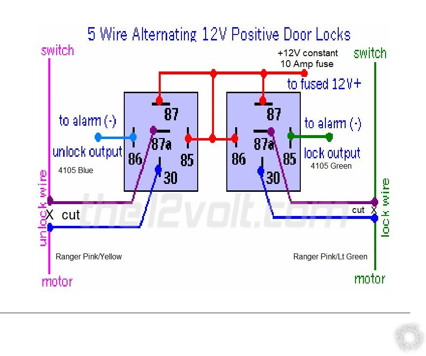
Basically you are cutting the vehicle wire and adding in the relay. The Rangers locks will function normally and the 4105 will be able to control the locks when necessary. ------------- Soldering is fun!
Posted By: jorms1
Date Posted: May 06, 2020 at 6:47 PM
Awesome that did it! thank you so much everything is working now.
Posted By: kreg357
Date Posted: May 07, 2020 at 7:37 AM
Good job! :^: Glad everything is working now.
-------------
Soldering is fun!
Posted By: jorms1
Date Posted: May 07, 2020 at 9:42 AM
All is working as I stated. locks and rs. Only thing i am struggling with now is the horn and lights, The picture i posted above shows the wires I am suppose to connect to. the brown park lamp wire is outputting constant 12v and i am connected right out of the back of switch. The horn wire yellow with blue stripe is also outputting constant 12v i am connected at the relay. I'm guessing the location is my issue with the horn. Since its suppose to be a negative input? Lights probably the same issue i should be on the switch output to the lights I am probably on the input the the switch. These are all just guess's but before i wrap it all up and tuck it away I want it to be complete. I did do the horn program to make sure the horn feature was enabled. 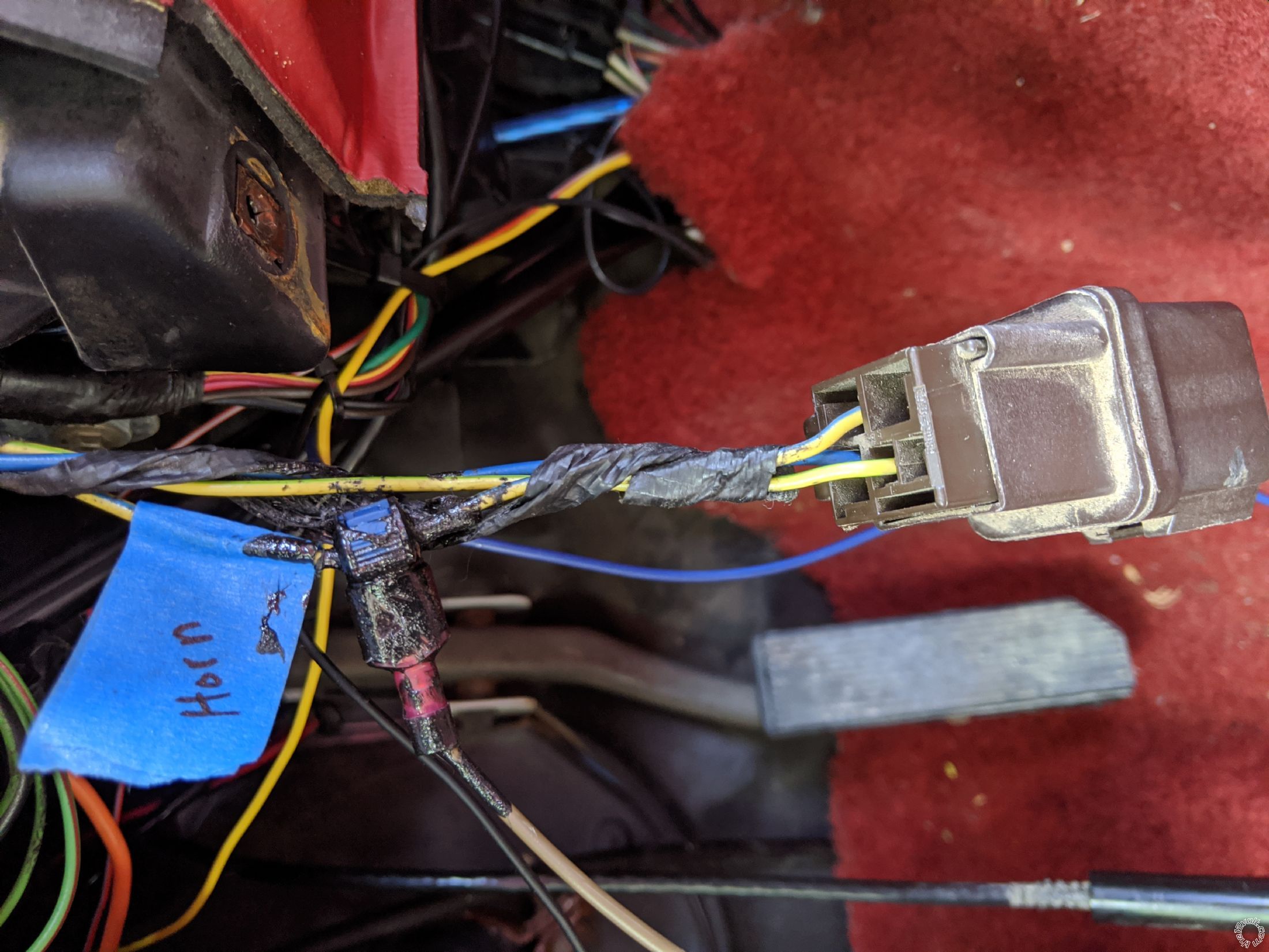 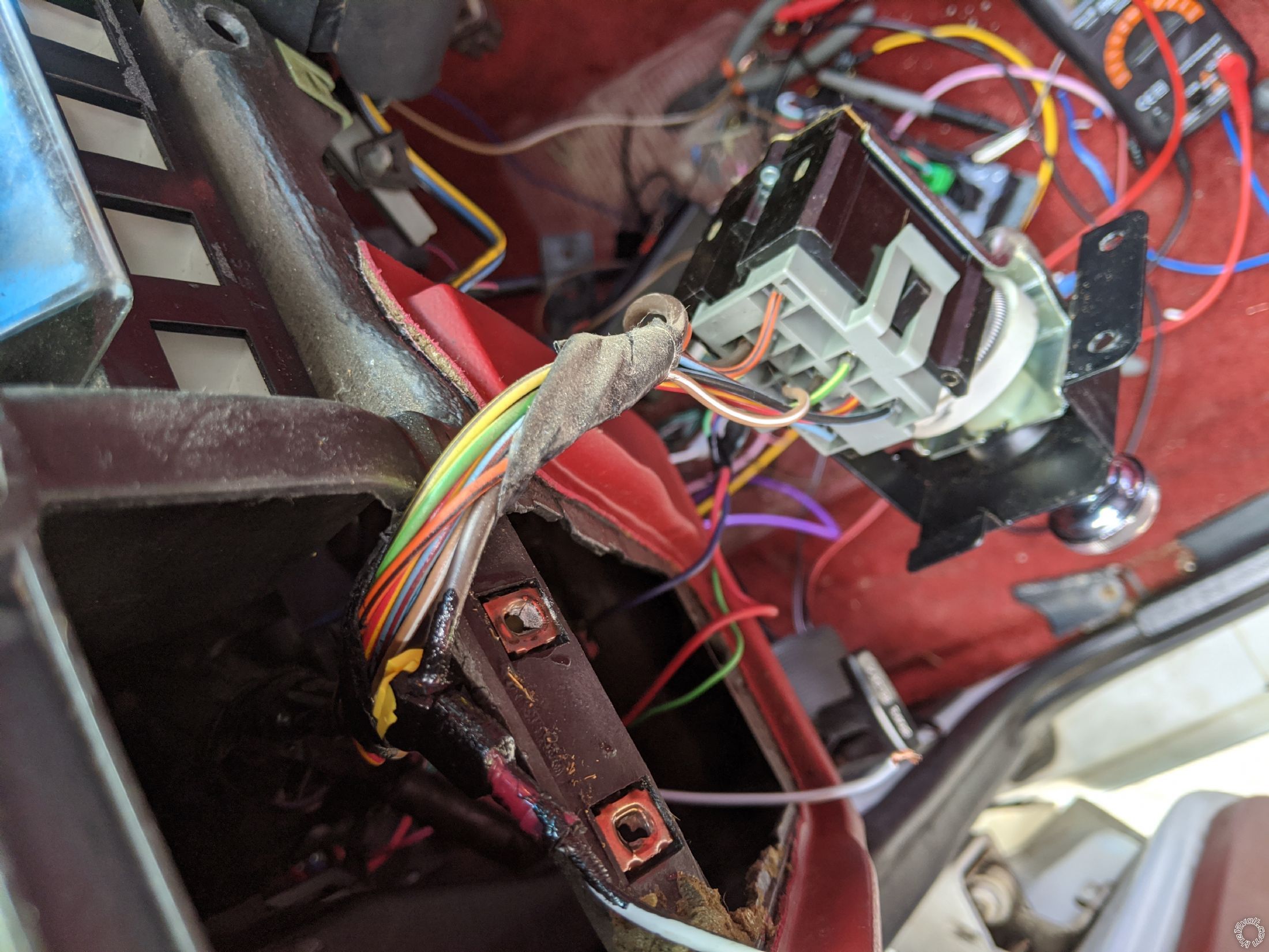
Posted By: kreg357
Date Posted: May 07, 2020 at 11:06 AM
You can easily test the (+) Brown Parking Light wire with a DMM. It should show +12V with either Parking Lights or Headlights ON. The issue might be the 4105 Parking Light output. There is a three pin jumper on the side of the 4105 control unit that allows you select either (+) or (-) output. It typically comes in the (+) output position but double check that the jumper is there and in the correct position for (+) output.
I usually grab the horn at the steering column. On most older Ford's it is Blue. You can test for this wire with a DMM. Set to 20V DC, Red lead to +12V constant and Black test lead to suspect Horn wire. You should get +12V when the horn button is pressed. Be careful in the steering column, any harness in Yellow or any Yellow connector/plug is for the Airbag. Sometimes Ford mixes regular wires in with air bag wires.
-------------
Soldering is fun!
Posted By: jorms1
Date Posted: May 09, 2020 at 3:44 PM
Thanks again Kreg357, I got the lights going. Not sure whats going on with the horn. I did what you said with no luck. I ordered a siren and will just install that lol. So all done with this project and i really appreciate your help.
|