2003 Ford Focus and Avital 5105L
Printed From: the12volt.comForum Name: Car Security and Convenience
Forum Discription: Car Alarms, Keyless Entries, Remote Starters, Immobilizer Bypasses, Sensors, Door Locks, Window Modules, Heated Mirrors, Heated Seats, etc.
URL: https://www.the12volt.com/installbay/forum_posts.asp?tid=146388
Printed Date: May 16, 2026 at 3:37 PM
Topic: 2003 Ford Focus and Avital 5105L
Posted By: xesvuli420
Subject: 2003 Ford Focus and Avital 5105L
Date Posted: August 12, 2020 at 1:28 PM
Hi everyone! Ive inherited a 2003 Ford Focus SE Wagon that I plan to convert to a 2 person camper, and so now its due for a ton of upgrades. So Far I have installed a aftermarket cruise control, a flip down dvd screen in the back, a backup camera, and 95% of a pioneer AVH-w4500NEX head unit. It has the Zetec engine and factory Blaupunkt radio. Those 2 options apparently make so much stuff different than the standard focus, almost every wire for the cruise control was wrong. So I think i am for sure gonna need some help. Not to mention that this time I plan to tackle an Avital remote start with security install myself. I have tinkered with wiring about 24 years, and I consider myself pretty knowledgeable, but again, Ive never done a remote start/security, or a immobilizer bypass before so Im sure that if I want to make it out alive then I need to double check my work! So I have signed up here hoping a few of you here will have the time to assist me in doing a good job. If so please read on, if not, thanks anyway!
OK so as far as the avital install, Im mostly still in the planning stages. Ive never done anything this tedious with wiring and Im the type to do it right, so Im mapping out the install before I even touch it. I welcome ANY and ALL tips you guys want to share to make my life easier.
My first question is about relays When do i need them versus when I dont? I plan to watch some videos on the matter before I start, but I'll take all the explanation I can get so I can pick up as many relays as needed. I know I want a few options that probably require them, but so far I haven't had a chance to figure this out. I will be wanting my horn to honk instead of siren, I do have a trunk release, I also want to wire the dome light supervision with the door input, (I cant remember exactly why, but I remember I got the tip from another installer. Something about the car light coming on when I unlock the door, and also the interior flashing when alarm goes off). I also think I need one for a starter kill too. Admittedly this is a weak spot for me, so any guidance here is well appreciated!
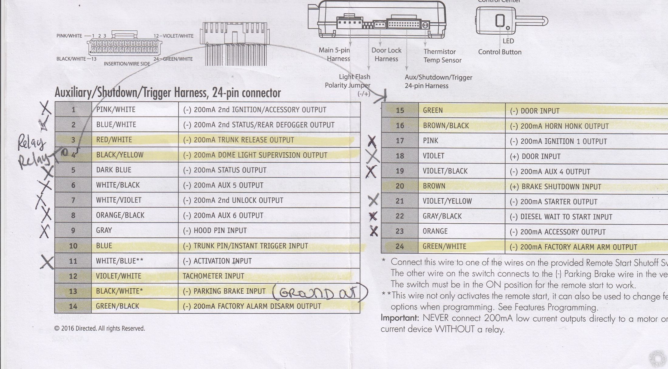
I think I have a factory alarm, I cant seem to get it to "go off". Ive tried locking the doors and then opening from the inside, kicking the tires hard, etc. I do have a blinky red led by my hazard selector, and a panic on the fob. I also have a yellow plug for the factory blaupunkt stereo that is as of now homeless. I think one of the wires in it is for the alarm too, but to date havent figured that problem out yet. Either way I believe I DO need to hook up wires 14 and 24 (from the attached documents)
I would also like to clean up the harnesses and remove as many wires as I can before install. Im definitely more of a tidy installer, so It would be ideal if I could hook up and tape everything on the bench first. Ill post up pics of the resources I'm working with so you guys have reference of what Im seeing too. On the following picture I am attempting to mark what I wont need for cutting. The X's are to be cut (if I'm correct that I dont need them, PLEASE tell me if im mistaken), The highlighter are the ones Ive confirmed I DO need (again, PLEASE tell me if I'm wrong on any), and the question marks I have no idea about. the blank ones under the REMOTE START section I havent looked up yet, but Im sure ill need most of these too! I welcome any opinions on this, have I made any errors yet?
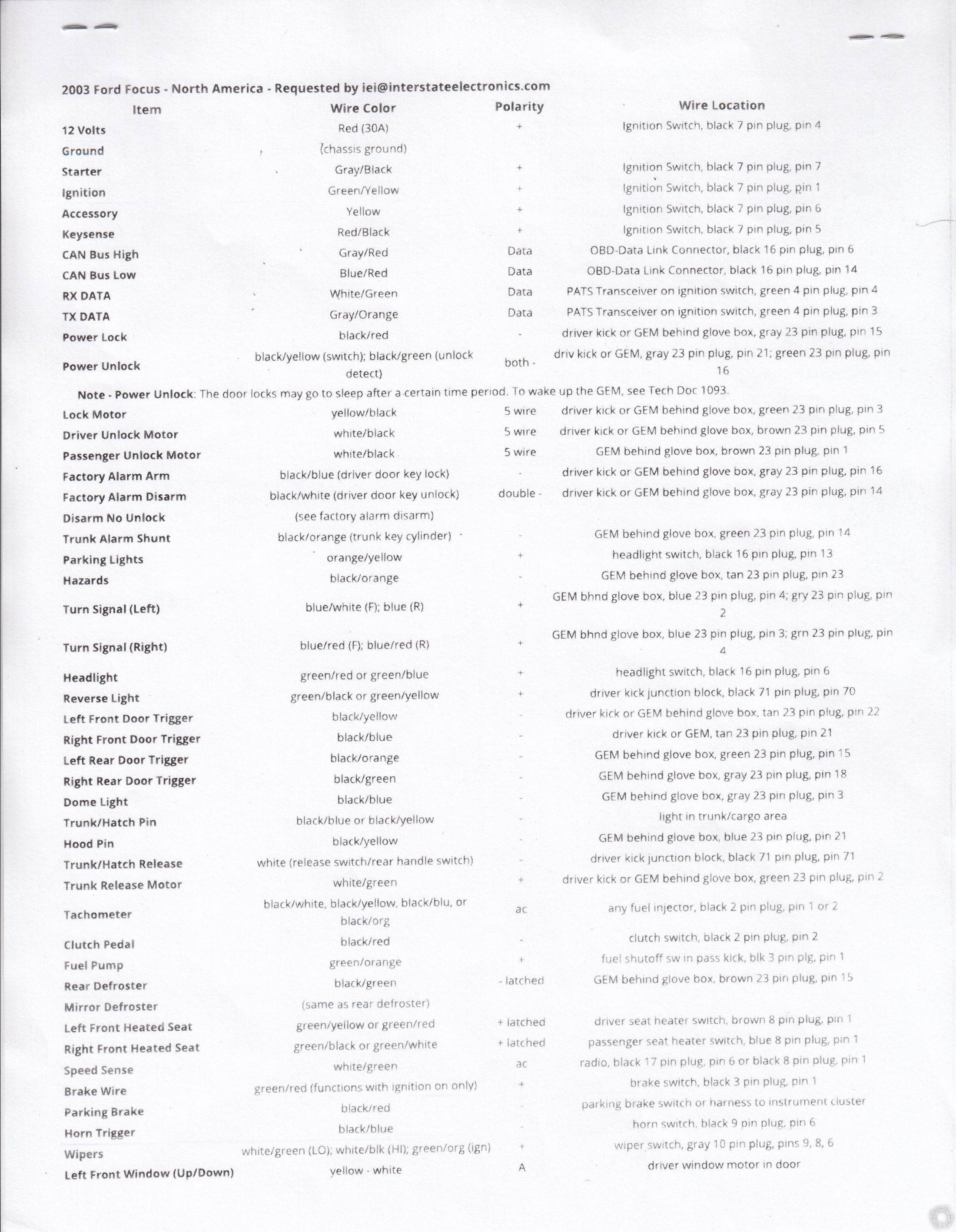
Here is my cars tip sheet, please let me know if you notice something that is incorrect due to my car being the Zetec, or blaupunkt, or whatever!
Thanks to everyone who takes the time to read and help me get through this. Im lucky to live in a time when I can get help from my peers on the task I chose to take on. I appreciate the learning Im about to do, and the time you guys are saving me, not to mention not pulling out all my hair.
OK so as far as the avital install, Im mostly still in the planning stages. Ive never done anything this tedious with wiring and Im the type to do it right, so Im mapping out the install before I even touch it. I welcome ANY and ALL tips you guys want to share to make my life easier.
My first question is about relays When do i need them versus when I dont? I plan to watch some videos on the matter before I start, but I'll take all the explanation I can get so I can pick up as many relays as needed. I know I want a few options that probably require them, but so far I haven't had a chance to figure this out. I will be wanting my horn to honk instead of siren, I do have a trunk release, I also want to wire the dome light supervision with the door input, (I cant remember exactly why, but I remember I got the tip from another installer. Something about the car light coming on when I unlock the door, and also the interior flashing when alarm goes off). I also think I need one for a starter kill too. Admittedly this is a weak spot for me, so any guidance here is well appreciated!
I think I have a factory alarm, I cant seem to get it to "go off". Ive tried locking the doors and then opening from the inside, kicking the tires hard, etc. I do have a blinky red led by my hazard selector, and a panic on the fob. I also have a yellow plug for the factory blaupunkt stereo that is as of now homeless. I think one of the wires in it is for the alarm too, but to date havent figured that problem out yet. Either way I believe I DO need to hook up wires 14 and 24 (from the attached documents)
I would also like to clean up the harnesses and remove as many wires as I can before install. Im definitely more of a tidy installer, so It would be ideal if I could hook up and tape everything on the bench first. Ill post up pics of the resources I'm working with so you guys have reference of what Im seeing too. On the following picture I am attempting to mark what I wont need for cutting. The X's are to be cut (if I'm correct that I dont need them, PLEASE tell me if im mistaken), The highlighter are the ones Ive confirmed I DO need (again, PLEASE tell me if I'm wrong on any), and the question marks I have no idea about. the blank ones under the REMOTE START section I havent looked up yet, but Im sure ill need most of these too! I welcome any opinions on this, have I made any errors yet?
Here is my cars tip sheet, please let me know if you notice something that is incorrect due to my car being the Zetec, or blaupunkt, or whatever!
Thanks to everyone who takes the time to read and help me get through this. Im lucky to live in a time when I can get help from my peers on the task I chose to take on. I appreciate the learning Im about to do, and the time you guys are saving me, not to mention not pulling out all my hair.
Replies:
Posted By: kreg357
Date Posted: August 12, 2020 at 9:40 PM
Well, lets start with the possibility of a Factory Alarm system. The easy test is to sit in the car, ensure all the doors are closed, then use the factory remote to Lock the car. Press the Lock button twice, then wait almost two minutes while watching the dash for a blinking Security light. If you see a light, watch to see if the blink pattern slows down as this indicates that the alarm in ON. Either way, after 2 minutes, open a door with the inside handle. If the horn starts beeping, you have the Factory Alarm. The Panic button on the factory remote does not indicate a Factory Alarm system is installed.
Next you should determine if you have the Ford PATS system. This is a transponder based ignition immobilizer system. Ways to tell... Do you have any plain hardware store style keys made that will start the car? If you wrap the plastic key head area with ~5 layers of aluminum foil first, will the car still start? Do you have a Green 4 pin plug ( with Pin 3 Gray/Orange and Pin 4 White/Green ) at the ignition switch? If your car has the PATS system, you will need a bypass module to allow the R/S system to start the engine.
If you car has the Ford GEM, it is possible the unlock function will "go to sleep" after the car is parked for a while. This will interfere with the 5105's ability to unlock it. There is a bunch of info about the GEM and waking up the GEM. Search in the Downloads Section for DEI TechTip 1093 for more info.
Being as you have an R/S with Alarm system, you will need some 1N400x diodes for the door trigger input to the 5105. Might want to order them now. Get a package of 10. 1N400x where the x can be 1, 4 or 7. The 1N4007 isn't any more expensive and can handle basic blocking/isolation duties plus relay coil quenching, too.
Post the 5105's other harness. We will need to see them for the Starter Kill function your want.
That should get you started for now.
-------------
Soldering is fun!
Posted By: xesvuli420
Date Posted: August 13, 2020 at 9:21 AM
My dude! Thank you for taking all that time to write that wonderful post. I cant wait to go into depth on it but I wanted to post a quick reply. I dont know if you noticed from my previous post but Ive already purchased the immobilizer. I purchased the Fortin EVO-ALL.
As far as security, I really think its on board. Ill test it as soon as I can to find out for sure, but theres too many clues that say its there. For instance a blinking red LED, A special wire that runs to the or Oem blaupunkt radio, and of course the panic. I will get you an update as soon as I confirm it.
As for the diodes, ill get them on order, but so far Ive watched about six videos with people installing remote start and security on different cars just to get a little acquainted with the process, and Ive seen nobody use any diodes yet Could you tell me more about them and what therefore? I definitely appreciate it. Also You advises to get 10 n1400x diodes, then you mention that the n14007s are better. Would 10 of those n14007s be sufficient, or should I purchase a mixture?
Also you didnt mention anything about relays Dont I need to get those as well? About how many do you think?
Ill be back shortly with the other answers!
Thank you greatly for jumping on this train, I honestly cant tell you how much I appreciate any and all advice you give.
Posted By: kreg357
Date Posted: August 13, 2020 at 9:53 AM
Ten 1N4007 diodes should be enough. The diodes will be used to combine the cars door triggers into one input for the 5105. The diodes keep each door isolated from the other doors so as not to upset the car.
Not sure if you will need any relays right now. The Trunk Release requires a straight (-) which the 5105 supplies. If the 5105 has an internal Starter Kill relay ( thick Green and Purple wires ) you won't need one there. If the Dome Light Supervision is done with a Door Trigger wire you won't need a relay there.
Sorry, I missed that about the EVO-ALL. Do you have the FlashLink cable to load the correct firmware onto the EVO-ALL ( currently at 71.46 ) or was the module flashed for you prior to shipment? Do you have two working factory keys available for EVO-ALL module programming? The EVO-ALL is a bit of overkill on your car. You might be better off with an EVO-Ride bypass if you have two keys. You could get one for $25 off EBay and save the EVO-ALL for the next install.
-------------
Soldering is fun!
Posted By: xesvuli420
Date Posted: August 13, 2020 at 6:29 PM
Ok Im back! Heres what I got
On the stock alarm, either I'm not doing something right or its not got one. There is a flashing led by the hazard switch, but it never changed speed ever. I sat in car with transponder key, locked doors waited 5 minutes, opened from inside, nothing. I rolled down the window, went 5 feet away, two times on the lock button and waited 5 more minutes. No alarm when i opened the door with the inside handle. Either i'm not setting it right, or despite the blinky light, the panic button, the extra wire to the blaupunkt radio thats a "security" wire, there isnt an alarm. What do you think is more likely?
As requested Ive printed out form 1093, and also 1076 for when the diodes come in. Ive now got 100 coming from amazon. It was cheaper and faster than getting a 10 pack on ebay. ETA Saturday! If you want some PM me with your address and I'll post you a bunch!
I followed the instructions to test for the GEM system. Note the instructions say its test procedure for trucks, but I couldnt find a car version any different so I proceeded. After the two minute mark (and immediately after as well) the unlock switch inside the car did not function at all. So I guess that confirms that.
As for the 5105 harness you wanted to see, have you noticed the attached documents from the original post? I believe it has what you want doesnt it? I can for sure grab a photo if needed. but isnt the resource above better?
I have the flash harness on order, I couldnt find a reasonably priced seller that did offer the pre-flashing. I got the Evo-all for 40$ so would it be more difficult to use? I really dont want to grab another unit unless its benefit is worth it. Ill rely on you to tell me that. What would be the difference since its already on order? I again appreciate the lesson!
Also, I dont think this kit requires but 1 ket to program if any.. Kinda the reason I went with Fortin, I dont have but the 1 key, but again, please confirm my impressions, I am the greenhorn here.
Well I think that catches me up with you, or at least until the components arrive. Im excited for the next step! Let me know what other things I could get ready in the mean time.
Also, since youre obviously very experienced, I wanted to ask a side question. Is there a way to hook this remote start to some type of battery meter so it would crank up if the level of charge drops past cranking abilities. For example, if we are watching dvds in the back, I would love it if the alarm would monitor and crank up as needed to keep the charge up despite the current draw. I know I have an unused wire that if grounded will start the car... has it been done?
Thank you again sir!!
Posted By: kreg357
Date Posted: August 13, 2020 at 9:51 PM
Sounds like you don't have a Factory Alarm but one last test to be sure. Sit in the car with the engine off. Open the drivers door and press the lock button then close the door. Wait the two minutes then open the door with the inside handle. No horn beeps, no alarm.
The GEM system make the install a bit more complicated but it is what it is. Good thing you got the extra diodes.
If you only have one working key, the EVO-ALL is a good choice. You will need the Fortin FlashLink cable for sure because with only one key you must use the D-Cryptor process. That's why I asked about the number of keys you had.
Your 5105 diagram post does not include the 10 Pin harness but if the install guide I found is correct, the 5105 has an internal Starter Kill relay.
Some R/S systems have the Low Battery Start built in. Yours does not have this feature (but it does have Low Temp Start). Setting up some sort of voltage monitoring system to trigger the 5105 Activation Input wire might be possible but I have no info on it.
-------------
Soldering is fun!
Posted By: xesvuli420
Date Posted: August 13, 2020 at 11:16 PM
Ok sitting in the car to type this post! Just threw the keys 20 away, locked the door, sit down and closed up the car. When I get done Ill pull the handle and we will see what happens. I hope nothing because A) the lady of the house is in bed above me, and more importantly B) I believe that means we dont have to hook up wires 12 and 24 yes?
As far as the GEM, yes if theres ever an extra step or two, it always always pertain to MY model no matter what equipment it is were dealing with. Thats just my luck. Oh well, if youre gonna swim, dive right? At least after this Ill be even more knowledgeable.
Ill check the harnesses soon and update back if there is in fact a 10 pin.
If you ever come up, or hear about a battery monitoring option, please come back. I already looked up some Avital models to see if I could just order and swap out the brain right now.. but I couldnt find a single model that mentioned it. Ill have to figure out something here, Ill want to be able to make it a few hours powering through pioneer and the flip down... lucky for me I dont have any aftermarket amps and subs to make it worse. If I could get through a double feature At the drive in in my teenager decked out integra, surely I can go longer on 1/4 of the juice. Just get a good battery. (Or 2)
Ok well Im sure its been 2 minutes, and Im out of thoughts for now so here we go.
3..
2..
1..
🦗 🦗 🦗
So confirmed! Shes a big fat liar lmao. Blinky light just for fun!
No horn, no lights, No alarm. I can cut wires 12 and 24 now correct?
Thanks again, talk soon!
Posted By: kreg357
Date Posted: August 14, 2020 at 7:32 AM
No horn, no lights, No alarm. I can cut wires 12 and 24 now correct?
I would make up a chart of the R/S connectors and where each wire will go. Post that chart for forum member review and recommendations. Once that is in place you can cut unused wires. I usually cut them at 2 inches, group them into bundles and put a piece of heat shrink tube over each bundle. Keeps things neat but allows for changes if necessary.
Ill check the harnesses soon and update back if there is in fact a 10 pin.
There is a 10 pin plug, it's for the ignition wires and it does have the two wires for Starter Kill.
I saw some +12V low battery monitors on EBay. The main issue would be getting a (-) pulse signal from it to initiate a R/S. Some units have a piezo siren but that would be a constant (+) signal probably. There are ways to convert a constant (+) to a pulse (-) but there could be extra current draw with all that extra circuitry. The reason that type of R/S was discontinued probably had to do with liability. You park the car in the garage for a week. Your bedroom is over top the garage... You wake up dead...
-------------
Soldering is fun!
Posted By: xesvuli420
Date Posted: August 14, 2020 at 8:19 AM
Ok Ill work up the chart today for review.
Yes I had considered the issue of if the car was always able to start with a low battery. I would definitely have to tie in something just for use when Im actually using the car, and not while its sitting in a garage or a parking space. I for sure dont want it always starting when its battery drop, just while Im inside of it. Maybe some big red button with a key like the nukes have Im with you on safety, safety first, but if theres a way to do it and be safe, lets git er done lol!
Thanks again for your wonderful information cant wait to talk again when I have more ready!
Posted By: kreg357
Date Posted: August 14, 2020 at 10:07 AM
While a bit manual in operation, you could get something like this :
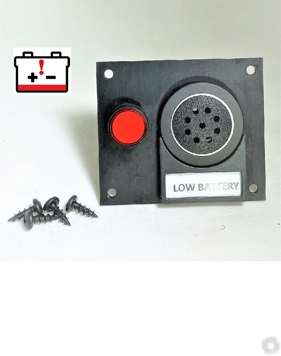
It's listed on EBay for $20. Search on "Labeled 12V Battery Low Voltage Detector Discharge Alarm Monitor w/ Mute Switch".
With a slight modification to the Mute button, pushing the Mute button would silence the speaker AND remote start the car...
-------------
Soldering is fun!
It's listed on EBay for $20. Search on "Labeled 12V Battery Low Voltage Detector Discharge Alarm Monitor w/ Mute Switch".
With a slight modification to the Mute button, pushing the Mute button would silence the speaker AND remote start the car...
-------------
Soldering is fun!
Posted By: xesvuli420
Date Posted: August 14, 2020 at 10:39 AM
Ill read up on it! I appreciate the link!
I have a bigger problem now. Somehow in wiring up an aftermarket cruise control, a pioneer head unit, a back up camera, a double usb Flush mount k (hooked into the pioneer) , and a flip down monitor in the back, some how Ive upset the air bag system. How in the hell did I do that?
Man this car is kicking the doodie out of me!
I need to walk away for a day or so 😡
Im just lucky I hit this wall BEFORE trying to install the avital.
Posted By: xesvuli420
Date Posted: August 19, 2020 at 5:10 PM
ok Hi all, Im back! Ive been working on a quick install cheat sheet of all the wires and locations and such. I'm almost finished, but I have some questions and concerns. my resources sometimes conflict with each other. Hopefully you guys can help me finish it, and maybe even check over it to make sure Ive got everything correct. I would love a double check before I screw something up. Check out the excel document ive created, and please please please try to find my errors. I want a bullet proof final draft if you guys feel like helping me out.
Let me explain the colors.
Grey I dont think i'm supposed to use at all, so safe for removal
Green Im hoping ive correctly sorted it out
Yellow I'm unsure about at this point
https://www.icloud.com/iclouddrive/0-E7qioyis3SREGEHsr8iDDzA#AVITAL_INSTALL
as you can see I have a few yellow areas.. Hopefully I can turn these green quickly.. let me start with a few questions..
1. Unlock output offers 2 choices, one for switch and one for detect. which one applies to me? I assume switch is for cars without keyless entry, and detect is for keyless..? Either way, I'm not sure here.
2. On the trunk release, my car tip sheet says I go to a white wire in the drivers kick panel, but my Fortin sheet says go to a black/yellow wire at trunk release switch under the drivers dash.Not sure which to follow.
3. I was suggested by a friend to make sure my Dome light supervision goes with the green door input wire to have the interior lights blink during alarm, and also to turn on lights when disarming alarm. but I am unsure what exactly I need to do to complete this circuit.
4. Lastly could someone help me understand where the wires go in the 3 yellow rows in the 10 pin harness area. Are these for a needed relay, or am i overthinking it?
Once I get to the bottom of those questions, and someone gives me the thumbs up on my excel cheat sheet, I will be ready to finally bench prep and install. I cant thank you guys enough for gettimg me this far! I look forward to any help you have to offer!
Thanks again!!!
Posted By: the12volt
Date Posted: August 19, 2020 at 5:40 PM
For those that do not have Excel to view your spreadsheet, here is a PDF copy.
-------------
 the12volt Support the12volt.com
-------------
the12volt Support the12volt.comPosted By: geepherder
Date Posted: August 19, 2020 at 5:43 PM
As far as the 10-pin harness, make sure you connect both the red and red/black to constant 12 volts. These provide power during remote start. The green is only used if you want starter kill. (You cut the factory starter wire and connect the side that goes to the ignition switch to this wire. The other side goes to the purple wire. If someone tries to start the car using a key when the alarm is armed, it will not crank.) If you don't want starter kill, just connect the purple to your car's starter wire.
-------------
My ex once told me I have a perfect face for radio.
-------------
My ex once told me I have a perfect face for radio.
Posted By: xesvuli420
Date Posted: August 20, 2020 at 11:04 AM
I have updated my sheet to show what you just said, I appreciate you helping me get the entire 10 pin harness complete.
Now just a few more things to figure out before Im ready to go. Anyone else can shed some light on the rest of the yellow rows?
Does anybody see any more mistakes on following sheet?
PDF
EXCEL
Thanks again guys, I cant tell you how much I appreciate the help!
Now just a few more things to figure out before Im ready to go. Anyone else can shed some light on the rest of the yellow rows?
Does anybody see any more mistakes on following sheet?
EXCEL
Thanks again guys, I cant tell you how much I appreciate the help!
Posted By: kreg357
Date Posted: August 20, 2020 at 5:51 PM
Nice work, the chart looks good. A few things to mention.
If you connect the Black/White Parking Brake input the the car, you must have the Parking Brake on to R/S the car. Most installers just connect this wire to Chassis Ground after verifying that the car won't start unless the transmission is in Park.
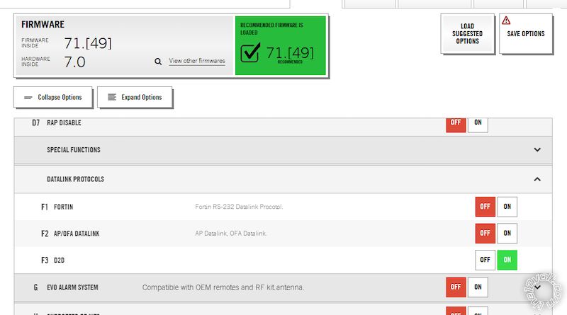
You didn't show the EVO-ALL 4 Pin harness. You could go D2D to the Avital DBI port BUT... You must flash the EVO-ALL with the correct firmware AND check the D2D box. I think this is Option F3 but I'm not positive. This option sets the EVO-ALL to use the DBI comm protocol rather than the Fortin or ADS protocol. You could go W2W with the EVO-ALL by connecting the Dark Blue GWR wire to the Avital's Dark Blue Status Output wire and connecting the Red and Black wires in the 4 Pin harness to +12V and Chassis Ground.
Here is the info on the door trigger wires. Use 4 diodes with the bands towards the car to combine the doors into one (-) input for the Avital.
Left Front Door Trigger black/yellow (-) driver kick or GEM behind glove box, tan 23 pin plug, pin 22
Right Front Door Trigger black/blue (-) driver kick or GEM, tan 23 pin plug, pin 21
Left Rear Door Trigger black/orange (-) GEM behind glove box, green 23 pin plug, pin 15
Right Rear Door Trigger black/green (-) GEM behind glove box, gray 23 pin plug, pin 18
You can connect the Avital's Dome Light Supervision to any door trigger wire.
-------------
Soldering is fun!
If you connect the Black/White Parking Brake input the the car, you must have the Parking Brake on to R/S the car. Most installers just connect this wire to Chassis Ground after verifying that the car won't start unless the transmission is in Park.
You didn't show the EVO-ALL 4 Pin harness. You could go D2D to the Avital DBI port BUT... You must flash the EVO-ALL with the correct firmware AND check the D2D box. I think this is Option F3 but I'm not positive. This option sets the EVO-ALL to use the DBI comm protocol rather than the Fortin or ADS protocol. You could go W2W with the EVO-ALL by connecting the Dark Blue GWR wire to the Avital's Dark Blue Status Output wire and connecting the Red and Black wires in the 4 Pin harness to +12V and Chassis Ground.
Here is the info on the door trigger wires. Use 4 diodes with the bands towards the car to combine the doors into one (-) input for the Avital.
Left Front Door Trigger black/yellow (-) driver kick or GEM behind glove box, tan 23 pin plug, pin 22
Right Front Door Trigger black/blue (-) driver kick or GEM, tan 23 pin plug, pin 21
Left Rear Door Trigger black/orange (-) GEM behind glove box, green 23 pin plug, pin 15
Right Rear Door Trigger black/green (-) GEM behind glove box, gray 23 pin plug, pin 18
You can connect the Avital's Dome Light Supervision to any door trigger wire.
-------------
Soldering is fun!
Posted By: xesvuli420
Date Posted: August 20, 2020 at 6:46 PM
Thanks for the compliment, I'm working to make it as good as it can be.
Right now im trying to figure out if I need a relay to starter kill. Am I totally missing it, or doesnt the violet wire out of the avital go straight to the cut starter wire on the starter side, and the green wire to the key side..? wouldn't this mean I don't need a relay? Yikes this last bit is getting me confused!
More great information, Gonna have to spend more time on these items to make sure I understand 100%.
I still have some questions though if anyone can help me with those..
1. Unlock output offers 2 choices, one for switch and one for detect. which one applies to me? I assume switch is for cars without keyless entry, and detect is for keyless..? Either way, I'm not sure here.
2. On the trunk release, my car tip sheet says I go to a white wire in the drivers kick panel, but my Fortin sheet says go to a black/yellow wire at trunk release switch under the drivers dash.Not sure which to follow.
Thanks again for helping me build up my knowledge on this. I am getting so much more well rounded thanks to all you guys!
Only 2 more to go!!! I may be getting close!!!
PDF
EXCEL
I'm begging you guys to find a problem in the above spreadsheet..
A few more days and i'll be ready to install, I hope everything is solid and signed off on by you guys here at this wonderful community!!!
Thanks again guys!
Right now im trying to figure out if I need a relay to starter kill. Am I totally missing it, or doesnt the violet wire out of the avital go straight to the cut starter wire on the starter side, and the green wire to the key side..? wouldn't this mean I don't need a relay? Yikes this last bit is getting me confused!
kreg357 wrote:On the cheat sheet, I have it wrote down to ground it out.. Are you saying that is wrong? or were you just adding theory for me to understand more of whats going on?
If you connect the Black/White Parking Brake input the the car, you must have the Parking Brake on to R/S the car. Most installers just connect this wire to Chassis Ground after verifying that the car won't start unless the transmission is in Park.
kreg357 wrote:Yea, I'm gonna need a lesson here on what I should do, pros and cons, etc. I'm also glad you said something because the Fortin instructions make it look like I can just simply plug the 4 pin avic-datalink into each unit on my vehicle specific instructions. Help me understand if you dont mind. I have the flash tool if we need to change anything to the flash. Just let me know what to do here.
You didn't show the EVO-ALL 4 Pin harness. You could go D2D to the Avital DBI port BUT... You must flash the EVO-ALL with the correct firmware AND check the D2D box. I think this is Option F3 but I'm not positive. This option sets the EVO-ALL to use the DBI comm protocol rather than the Fortin or ADS protocol. You could go W2W with the EVO-ALL by connecting the Dark Blue GWR wire to the Avital's Dark Blue Status Output wire and connecting the Red and Black wires in the 4 Pin harness to +12V and Chassis Ground.
kreg357 wrote:So please let me make sure I got this right.. diode out from the above mentioned pins all to the 1 green "door input" wire of the avital, also tie in the dome supervision to the same green wire. That will complete the circuit correctly?
Here is the info on the door trigger wires. Use 4 diodes with the bands towards the car to combine the doors into one (-) input for the Avital.
Left Front Door Trigger black/yellow (-) driver kick or GEM behind glove box, tan 23 pin plug, pin 22
Right Front Door Trigger black/blue (-) driver kick or GEM, tan 23 pin plug, pin 21
Left Rear Door Trigger black/orange (-) GEM behind glove box, green 23 pin plug, pin 15
Right Rear Door Trigger black/green (-) GEM behind glove box, gray 23 pin plug, pin 18
You can connect the Avital's Dome Light Supervision to any door trigger wire.
More great information, Gonna have to spend more time on these items to make sure I understand 100%.
I still have some questions though if anyone can help me with those..
1. Unlock output offers 2 choices, one for switch and one for detect. which one applies to me? I assume switch is for cars without keyless entry, and detect is for keyless..? Either way, I'm not sure here.
2. On the trunk release, my car tip sheet says I go to a white wire in the drivers kick panel, but my Fortin sheet says go to a black/yellow wire at trunk release switch under the drivers dash.Not sure which to follow.
Thanks again for helping me build up my knowledge on this. I am getting so much more well rounded thanks to all you guys!
Only 2 more to go!!! I may be getting close!!!
EXCEL
I'm begging you guys to find a problem in the above spreadsheet..
A few more days and i'll be ready to install, I hope everything is solid and signed off on by you guys here at this wonderful community!!!
Thanks again guys!
Posted By: kreg357
Date Posted: August 20, 2020 at 7:20 PM
No extra/external relay needed for Starter Kill. The Avital has an internal relay for this purpose.
I mis-read your chart on the Parking Brake wire. You've got it correct for an AT vehicle.
You must connect the Avital Dome Supervision wire to a door trigger wire on the car side of the diode.
To me, it's just as easy to go W2W between the Avital and the EVO-ALL. It's just 3 more wires to connect during bench prep. D2D should work fine if you have the correct D2D harness and can find the DBI D2D feature in the EVO-ALL's flash programming.
-------------
Soldering is fun!
Posted By: xesvuli420
Date Posted: August 20, 2020 at 9:06 PM
ok lets talk about this D2D, when you say the correct harness... is this it?
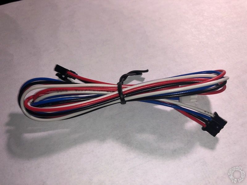
As far as the flash options, I went in to find and set it to D2D, but it looks like its already set.. right?
So now the module is ready to use the 4 pin plug on both modules without the need to go w2w right?
as always, I appreciate the education!
As far as the flash options, I went in to find and set it to D2D, but it looks like its already set.. right?
So now the module is ready to use the 4 pin plug on both modules without the need to go w2w right?
as always, I appreciate the education!
Posted By: kreg357
Date Posted: August 20, 2020 at 9:59 PM
The EVO-ALL option is correct, F3 for DBI D2D. Not sure about that cable. Will it plug into the correct port on the Avital? With the iDatalink units, the Avital/Viper side is either Brown or Red.
-------------
Soldering is fun!
-------------
Soldering is fun!
Posted By: xesvuli420
Date Posted: August 20, 2020 at 10:42 PM
Damn, I guess I dont.. I thought it plugged into the avitals black port, which I assumed was D2D. it doesnt, and isnt. I guess this only connects fortin to fortin. I guess its back to W2W than.
Posted By: xesvuli420
Date Posted: August 20, 2020 at 11:10 PM
Damn, I guess I dont.. I thought it plugged into the avitals black port, which I assumed was D2D. it doesnt, and isnt. I guess this only connects fortin to fortin. I guess its back to W2W then.
I updated the options in the flashlink to F1 Fortin Protocol, and also the sheet to reflect going back to W2W, could you give it a look and make sure Im understanding you correctly. leave the white wire alone, and hook the other 3 to the avital harnesses.
PDF
EXCEL
Thanks again!
I updated the options in the flashlink to F1 Fortin Protocol, and also the sheet to reflect going back to W2W, could you give it a look and make sure Im understanding you correctly. leave the white wire alone, and hook the other 3 to the avital harnesses.
EXCEL
Thanks again!
Posted By: kreg357
Date Posted: August 21, 2020 at 6:58 AM
A few minor things on the PDF file.
Typo on the pin numbers for where the EVO-ALL 4 Pin plug Red and Black wires go to. +12V constant goes to Avital Red at Pin 3 and Black goes to Pin 1. The Blue wire on that Avital 4 Pin plug is not used. You will connect Avital Status Output to the Dark Blue wire at Pin A8. It's shown as a dashed line.
I would combine all the Avital +12V input wires into one wire fused at 30 Amps and connect that one wire to the 12V source.
Ensure that the Avital Parking Light jumper is present and set to (+). It should come that way as a default.
Being as you are going W2W it really doesn't matter whether the EVO-ALL is flashed with F3 set. The EVO-ALL will see no data on the 4 Pin plug data wires and the GWR wire in use and go W2W.
-------------
Soldering is fun!
Posted By: xesvuli420
Date Posted: August 21, 2020 at 10:11 AM
Thank you! All those have been corrected!
Thanks to you, I believe I have enough now to start on the bench prep. Again I really appreciate you helping me get to this point. I will say that the progress to this point definitely has offered a ton to learn. Im grateful for my knew knowledge and cant wait to see how it pays off on the actual install.
I'll probabaly start cutting wires and taping up everything tomorrow. Ill be back to post up an update soon.
As always, My sincerest appreciation for all of you!
Posted By: kreg357
Date Posted: August 21, 2020 at 11:29 AM
A few minor things on the PDF file.
EVO-ALL 20 Pin harness, Pin A8 is GWR and should be noted as going to Avital Status Output. Avital 24 Pin, Pin 12 Tach should be noted as Any Injector, non-common color wire ( not GROUND ).
There might be some programming to be done on the Avital ( double Unlock if GEM needs it ), plus a Tach Learn, etc.
-------------
Soldering is fun!
Posted By: xesvuli420
Date Posted: August 21, 2020 at 4:53 PM
Good catch, I was so tired last night I sure forgot to fix the Fortin a8 row, I appreciate the eagle eye!
Ok maybe NOW its correct lol.
Thank you
Ok maybe NOW its correct lol.
Thank you
Posted By: kreg357
Date Posted: August 22, 2020 at 11:02 AM
Being as you are not using the Avitals Blue/White 2nd Status wire, with a bit of testing and some programing, you can add the convenience of turning on the Rear Defrost during a R/S. Here is the wire info from two sources :
Rear Defrost GREEN/BLUE (-) AT DEFROST SWITCH
Rear Defroster black/green (-) latched @ GEM behind glove box, brown 23 pin plug, pin 15
Use you Digital Multi Meter set to 20 VDC with Red lead to +12V constant and Black test lead to either wire. Turn on the Rear Defrost. If it's "latched" you will get +12V on the DMM for the entire Defrost run time. If it's a single pulse, then +12V when the button is pressed. Set the Avital programming accordingly and make the wire connection.
For the Dome Light Supervision, try the wire listed below instead of a door trigger wire.
Dome Light black/blue (-) GEM behind glove box, gray 23 pin plug, pin 3
-------------
Soldering is fun!
Posted By: xesvuli420
Date Posted: August 22, 2020 at 12:20 PM
Man that sounds like a great tip!
Unfortunately this focus is only going to be used when going on long multi-week roadtrips, and I use the rear as my motel room. If it gets too cold at night to sleep comfortably, or vice versa when its hot, Its great to wake up and be able to simply reach over and hit the remote start, and in a few minutes all is well and comfortable again for a few more hours. As you can imagine though, when you're sleeping in the car the windows stay defrosted even if you're in bomb cyclone lol. The rest of the time it will sit in my driveway and wont be used. I have an RS for my "daily", and a SportTrac for when I need to go to "work". That feature would 100% be beneficial on my truck. Most likely if i'm remote starting it, its because I'm inside and it is not. Although my first 10,000 mile road trip was in the RS, I think the SE Wagon will take on that job going further. Once I finish this job successfully, you had best believe the SportTrac will get an R/S as well. The RS however sleeps inside every night, so It will probably remain stock.
So either way I appreciate that tip, I'm sure I will use it on the next one!
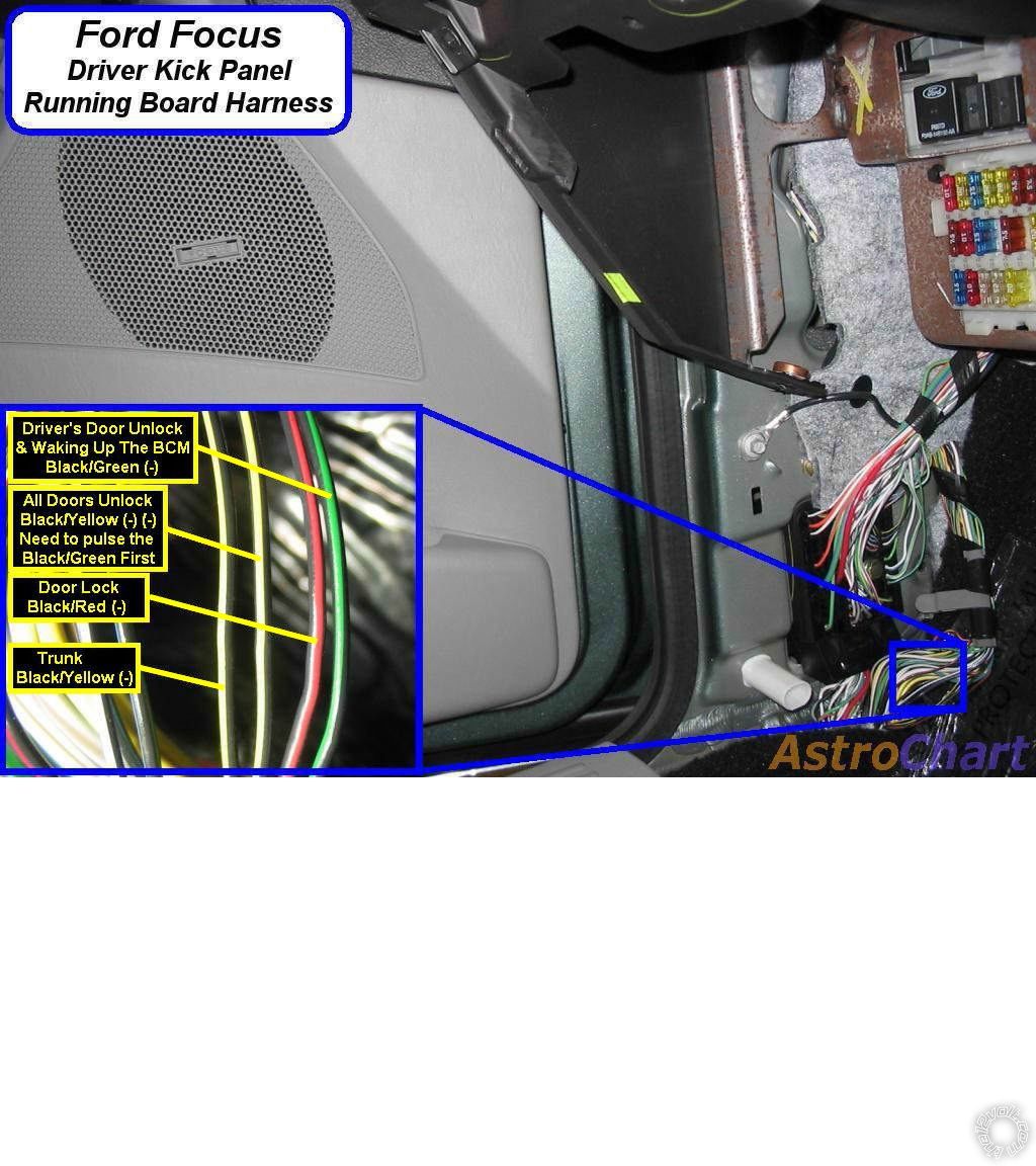
Also, I found this to be the best diagram for waking up the GEM. Its from an 05 ff wagon, but all the other diagrams I came across were for other fords, and not the focus. Do you see any issues with it?
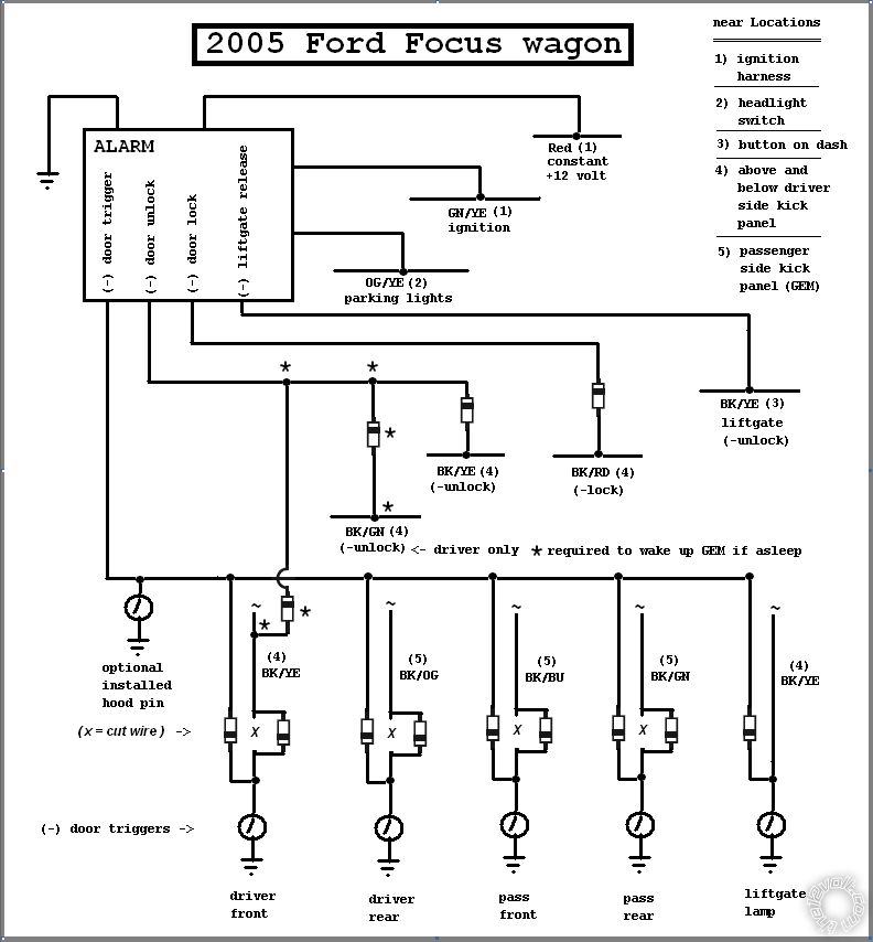
Won't be long now, I'm getting excited!
Thanks yet again!
Unfortunately this focus is only going to be used when going on long multi-week roadtrips, and I use the rear as my motel room. If it gets too cold at night to sleep comfortably, or vice versa when its hot, Its great to wake up and be able to simply reach over and hit the remote start, and in a few minutes all is well and comfortable again for a few more hours. As you can imagine though, when you're sleeping in the car the windows stay defrosted even if you're in bomb cyclone lol. The rest of the time it will sit in my driveway and wont be used. I have an RS for my "daily", and a SportTrac for when I need to go to "work". That feature would 100% be beneficial on my truck. Most likely if i'm remote starting it, its because I'm inside and it is not. Although my first 10,000 mile road trip was in the RS, I think the SE Wagon will take on that job going further. Once I finish this job successfully, you had best believe the SportTrac will get an R/S as well. The RS however sleeps inside every night, so It will probably remain stock.
So either way I appreciate that tip, I'm sure I will use it on the next one!
Also, I found this to be the best diagram for waking up the GEM. Its from an 05 ff wagon, but all the other diagrams I came across were for other fords, and not the focus. Do you see any issues with it?
Won't be long now, I'm getting excited!
Thanks yet again!
Posted By: kreg357
Date Posted: August 22, 2020 at 2:17 PM
Some info states that the GEM wakeup pulse to the Black/Green Drivers Door Unlock must come first so a Double Unlock Pulse might be required. Testing will tell.
-------------
Soldering is fun!
-------------
Soldering is fun!
Posted By: xesvuli420
Date Posted: August 22, 2020 at 2:19 PM
Thats what Im getting too. Setting the alarm to double pulse will be done while programming though correct?
Posted By: kreg357
Date Posted: August 22, 2020 at 2:35 PM
Yes it is a programming option with the Avital 5105.
-------------
Soldering is fun!
-------------
Soldering is fun!
Posted By: xesvuli420
Date Posted: August 23, 2020 at 5:01 PM
ok, I'm building the harness now and wanted to clarify a few things before I tape it up.
1. Is it ok to connect the black wire for parking brake ground on the the Avital 5 pin, pin 1 to the Avital 24 pin, pin 13, black chassis ground wire?
2. Is it ok to connect both the red and the red/black wire for constant 12v on the Avital 10 pin plug, pins 2 and 5, to the Avital 5 pin plug, pin 3, red 12v wire?
3. Is it ok to connect the yellow wire for ignition on the Fortin 20 pin plug, pin 1, to the Avital 10 pin plug, pin 6, green Ignition(key side) wire?
Thanks again for these answers, just want to make sure the harness is a efficient as it can be.
Posted By: kreg357
Date Posted: August 23, 2020 at 5:25 PM
Answers:
1. Yes. I do that and run the thicker wire to vehicle ground.
2. Maybe. The two thicker 10 Pin plug wires can be combined and run to the 30 amp supply at the ignition switch harness. The only slight issue is while the 5105 doesn't draw much power internally, you are running a (+) Parking Light output. Chances are you could combine all Reds and run off that lone 30 amp vehicle supply but... I would look for another +12V constant source and connect the 5 pin Red to that.
3. Probably a typo. You can connect the EVO-ALL Yellow IGN input wire to the Avital thick Pink IGN1 wire right by the 5105 and then run that same Pink wire to the vehicles IGN wire at the ignition switch harness.
-------------
Soldering is fun!
Posted By: xesvuli420
Date Posted: August 23, 2020 at 6:01 PM
Awesome, Thank you! I have connected the red/black to the red on the 10 pin harness. Then I'll connect the red on the 10 pin harness to the 30 amp supply at the ignition switch. Ill then connect the red from the 5 pin to somewhere in the fusebox with constant 12v. I'm getting so close I can taste it. Sundays are my day to do absolutely nothing, but as you see ive been bitten by the bug.
I also wanted to share with you my ugly monster! Normally I'm the type to twist the wires with the drill, but I am way too new for that magic trick. Its a pack of zipties and black tape for the first one, and I'm already glad I made that decision as ive had to re do the routing like 3 times to get it where I'm happy. I sure hope I got it all right, that black tape seems to melts into itself.
Anyways here it is in all its glory, please dont mind the dirty porch its well used and as you can see needs a dusting!
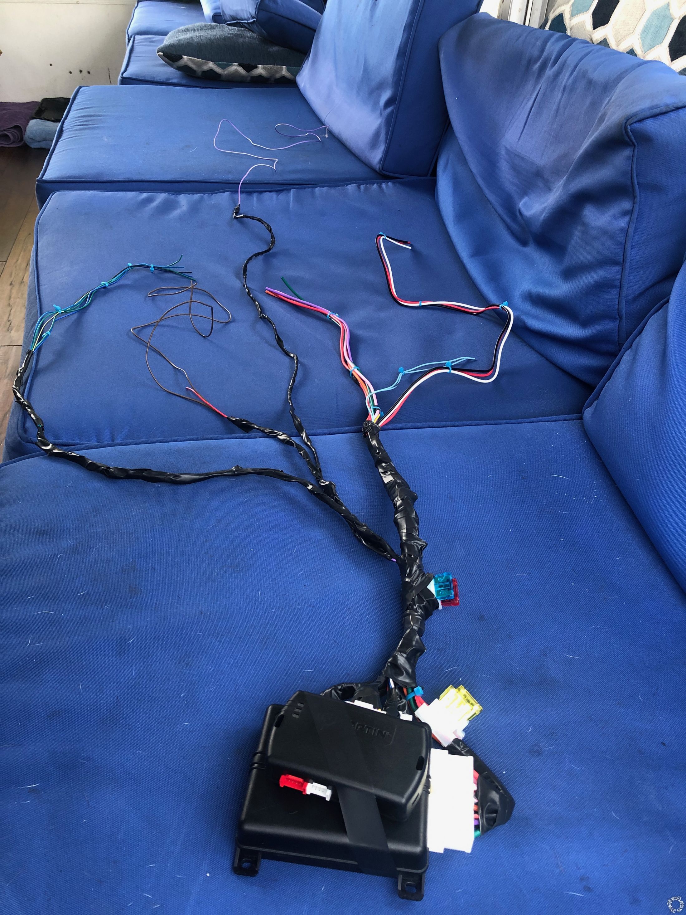
Posted By: kreg357
Date Posted: August 23, 2020 at 6:17 PM
Looks good. On the next one, get yourself a roll of Tesa Tape #51036. The 3/4" width is a good size. Makes the harness runs look factory and it leaves no residue if you have to make changes.
-------------
Soldering is fun!
-------------
Soldering is fun!
Posted By: xesvuli420
Date Posted: August 23, 2020 at 6:27 PM
Great tip! Sounds like something i need to add to my next amazon order.
I made a quick install version of my sheet. Its looking more and more manageable every day! I still have to get a relay and make some diode wires, but this install is about to hit high gear.
PDF
EXCEL
Thank you again bro for being on this forum, and participating in my thread. Im already at max capacity for appreciation for you sir!
I made a quick install version of my sheet. Its looking more and more manageable every day! I still have to get a relay and make some diode wires, but this install is about to hit high gear.
EXCEL
Thank you again bro for being on this forum, and participating in my thread. Im already at max capacity for appreciation for you sir!
Posted By: xesvuli420
Date Posted: August 25, 2020 at 7:16 PM
Hello again!
I'm 5 wires away from completing all the necessary connections and powering up the Avital module for the first time. I saved the sonofabeeche connections for last. Im down to the driver kick panel for the unlock, lock, dome light supervision, and the instant door/trunk triggers. Of course that requires doing the GEM wakeup as part of the installation. I will tackle this tomorrow, but its got me thinking, now that all the tedious work is over, I have no idea about what to expect when I finally plug that 12v constant from the 5 pin plug into the fuse panel for the first time.
I also assume at this point since my starter wire has been cut and spliced into the Avital that the car is dead now until I finish the install and plug in the Avital's 12v power wire to let it take its control.. Is this correct or will the car still start with the power off to the Avital module? I'm just curious about that. I dont plan on touching the key until after tomorrow.
Speaking of tomorrow, please let me know what to expect when I finally take the system online. I will wire up the GEM wakeup first, and save the 12v to the Avital to be the very last wire connected. When I plug that 12v connection in, and the Avital gets a closed circuit for the first time, assuming I have done a good job on all the connections, what do I need to expect? What do I do next? I have the Avital to program, at least to a double pulse unlock, and also the Fortin module needs to be programmed. I have a doodie ton to read tonight on the Decrypter instructions, as well as the Avitals operations, but a laymans approach would be appreciated!
Tomorrow is either going to be a great day, or a horocious one depending on my install to this point. Please keep this Noob in your thoughts as the moment of truth comes to present!
Posted By: kreg357
Date Posted: August 25, 2020 at 9:47 PM
What happens when I plug in the R/S system?
The fuses should be removed and all the R/S harnesses plugged in. When all is ready, plug in the fuses. What happens depends on the vehicle / system / bypass module, etc. In your case, not too much. Verify that the fuse(s) doesn't blow. Next ensure that the car works like normal with the factory remote and starts with the key.
The cut Starter wire will not be an issue if you made proper connections to it. The internal Starter Kill relay has the cut Starter wire going thru it, Pin 87a to Pin 30, so even without R/S power the car will start like normal.
Your next step is to program the EVO-ALL bypass module to the car. If you only have one working key, follow the 1 Key programming procedure. Verify that each step follows the guide. You might have to scroll down to see all DCryptor info on the PC screen and complete that process.
After that you can warm up the engine and do the Tach Learn process as detailed in the Avital install manual.
Next would be to test the Avitals Lock and Unlock control. Test the Unlock before the 2 minute GEM sleep and then test after the 2 minute sleep. Try a trunk release.
Verify that the Parking Lights flash with lock and unlock.
Try a R/S. Watch the Instrument Panel to see the ignition come ON and then the engine cranks. Look for any "Security" indicators on the IP. If the engine starts, listen for over/under crank. Let it idle for a minute and then depress the Brake Pedal. The engine should shutdown. Start the engine again and then pop the hood. The engine should shutdown. Start the engine again and try a "key takeover" by inserting the key, turning to RUN and then stepping on the Brake Pedal. The Parking Lights should go off and the engine should keep running.
The Avital RKE functions can work even though the R/S function has problems and visa-versa. If there are any issues, look at them one at a time. Typically, if your planning, prep and connections are correct and solid, you won't have any issues. Setting the Avital to Double Pulse Unlock can be the last thing you do, and it might be the most difficult ( using the Avital remotes ). Take your time, drink plenty of water and enjoy the moment.
At this point you can test the Avital's alarm system.
Below is some info on the lock wires.
-------------
Soldering is fun!
Posted By: xesvuli420
Date Posted: August 26, 2020 at 12:48 PM
Well that didnt take long lol. Im stuck already. I decided to start on my easiest wire and try to tackle the LOCK trigger. I looked at my schematic and went off in search of a BLACK/RED. I found one above the kick panel and wired in the diode... Then I got to thinking I had better not assume anything so I went back to the loom and sure enough was another BLACK/RED. I disconnected the diode and hooked the meter up to verify its locking function. To my surprise its fully grounded with key off. I hooked my meter up red side to a 12v constant at the fuse panel, and then black side to the BLACK/RED. It imediately gives me 12v on the display.
If I understand this correctly I should get a pulse of ground when the LOCK function is activated by the doors or remote.
So I moved on to the other BLACK/RED wire. It also is fully grounded.
So I decided to come back here for an explanation or what i'm doing wrong, and I saw your post with the included picture showing wire location. Your BLACK/RED is located a totally different location. A much better accessible location then I was way up inside the back of the dash behind the fuses. I just figured the guy that drew out the GEM bypass module didn't know it was here too.
So I pull up the carpet and whatever you call the sound blanket underneath and I locate the BLACK/RED in the pictured loom. It too has ground all the time!
What am I not understanding?!? Should't it be pretty much OFL or close to it until you engage the LOCK feature? So far all the other wires have tested this way. 00.00.01 or something like that, and then 11.##+ when I activate funtion.
I'm gonna need more water lol.
I installed an empty 20a fuse for the 12v constant from the 5 pin Avital plug going to the fuse panel. Now when I plug the fuse in the system will hopefully go online.
Also, on the shock sensor there is a green wire.. I just ignore this wire as its for expandability right?
Thanks again sir
Posted By: kreg357
Date Posted: August 26, 2020 at 2:06 PM
Your basic understanding on the (-) signals is correct. Ignoring what you see when you're in a static condition, you should see the +12V when you have the signal present. Sometimes to see a lock signal the wire used is actually the lock cylinder key output. This means to see the wire under test do anything you must insert the key into that doors' lock cylinder and rotate the key. I typically use a "computer safe" LED test light. It will show a Green LED when a (-) signal is present and a Red LED with a (+) signal is present. Being as you are cutting this wire to add the diode, you could cut the wire and test the lock function ( with key, button and/or FOB ) to see if it is the right wire.
I have had a few where there is no way to test the wire. In those rare situations I do everything to ensure I'm on the correct wire from all of the available wiring sources and very sure it's the correct wire, then I connect the R/S's lock wire and press Lock to see if it works the circuit. This is a better way than using a jumper to chassis ground because the R/S's lock output is rated at 200mA. In your case I'm sure there are several Black/Red's in the door sill bundle. Go by gauge, appearance, proximity to unlocks wires and testing to rule out other wires, etc. Worst case, go to another location where the Plug and Pin are specified.
I had one where the customer lost the factory remotes so I couldn't use them to test for the trunk pop wire. The interior release was mechanical, so no help there. The wire guides said it was a (+) signal in a Brown wire in the door sill harness. There were 4 Brown wires in that harness... I ended up going into the trunk. removing trim to see the trunk solenoid connector to get an idea of Brown wire color and gauge, then found the most likely wire in the door sill. Cut it and them
ohmed it out to the trunk solenoid connector. Simple job took an extra 30 minutes.
-------------
Soldering is fun!
Posted By: kreg357
Date Posted: August 26, 2020 at 2:16 PM
Also, on the shock sensor there is a green wire.. I just ignore this wire as its for expandability right?
I'm not a big DEI person but I believe you are correct.
-------------
Soldering is fun!
I'm not a big DEI person but I believe you are correct.
-------------
Soldering is fun!
Posted By: xesvuli420
Date Posted: August 26, 2020 at 2:52 PM
Well lets talk about this, according to my diagram I dont cut the BLACK/RED, I just connect to it with a diode to the door lock output. Is that incorrect? (I do cut all the trigger wires, but not the lock/unlock wires.. right)
Also on this wire I get constant ground, but its the only BLACK/RED one down here. I dont quite understand it, but if its the only one than it has to be the right one correct? Should I just attach It with a diode with the band on the Avital side of the door lock output?
I also need some clarification on all the BLACK/YELLOW wires. I only have 2 in this loom. One has been confirmed to throw ground when the trunk open button is pressed, The other is the same as above, Its constant ground while locked, unlocked, whatever.
Im also confused because on the schematic, it is mentioned as the unlock all doors wire, but in the same location Im supposed to have another BLACK/YELLOW that is supposed to be driver door trigger that I am supposed to cut, and also a lift gate lamp BLACK/YELLOW trigger wire also in this same spot.. Am I supposed to be using the BLACK/YELLOW trunk wire that signals when I hit the button or is there a separate Lamp wire I also need to find.
I feel like Im totally missing something here.
Time for more water 🤓
Posted By: kreg357
Date Posted: August 26, 2020 at 4:18 PM
Yes, only the door trigger wires need to be cut, not the door lock wire. While it is temporarily invasive, cutting the wire to verify it's function is one way to verify it. With solder and heat shrink tube, the repair is solid and reliable. The cut test and the Avital connection test should not cause any harm and will verify the wire. Of course, for certainty, you could go directly to the GEM, Grey 23 Pin Plug, Pin 15 for the Black/Red Lock wire. The Black/Yellow for Unlock is at the GEM, same plug, Pin 16. The Black/Yellow door trigger wire can be found at the GEM, Tan 23 Pin Plug, Pin 22.
While Bulldog Security, Fortin, DEI and iDatalink show the Lock wire as Black/Red another site has this info
Lock BLACK/ORANGE @ DRIVERS KICK PANEL
The 2004 Focus is Black/Orange so this info could be a mistake on this companies part.
I believe that I noticed that multiple Black/Yellow wire issue while researching your project. Pretty sure they come from different pins on the GEM. Hopefully they test via DMM without issue.
The only Focus from that era I kept notes on was a 2003 ZX3 that didn't even have power locks. I added an aftermarket power lock kit with the R/S system so I never had to look for the factory lock wires plus no GEM.
-------------
Soldering is fun!
Posted By: xesvuli420
Date Posted: August 26, 2020 at 7:17 PM
Ok I am officially mentally exhausted from today!
It has been a long aggravating day of finding multiple wires by color, only to not be the right ones. I'm so wizzed off at the quality of my resources versus the actual application. I still have 1 wire left to hook up, its the blue trunk instant trigger on pin 10 of the 24 pin Avital harness that I am struggling to find. every resource says find it in a different place. I will attempt this again tomorrow. Everything else is hooked up as it should be, or at least how it is in the schematics I have been following. I wont say I didnt make any mistakes, but I really really tried my best to make solid connections, and tape them tight.
Anyways, so the good news is the fuse didnt pop when I put it in... and thats about it lol.
I put the fuse in, when nothing popped or started smoking I sat in the car, held my breath and hit LOCK on the Avital remote.
To my sheer disbelief all 4 doors locked, I'm not 100% sure, but It definitely made a thunk sound in stereo. I'll check each one soon enough. I hit unlock, all seemed to unlock. I hit lock again and to my disbelief it seemed to function correctly. I decided to test it and make sure my eyes wernt fooling me and grabbed for the inside door handle. I forgot on this car that when you do that It will actually open the door, so of course I set my alarm off for the first time. lmao.
UPDATE
All doors and the trunk do lock and unlock just fine.
Unfortunately I couldnt get it to shut up after that. None of the buttons on either the Avital or Ford fobs stop its siren. I eventually pulled the fuse, and when it shut up I waited about 10 seconds and put the fuse back in and it was still going off. I pulled it out again, laid it down, and decided it was time for a much needed smoke break at this point.
UPDATE
I apparently wasnt holding down the button long enough. It seems you need to have a longer press to actually activate the buttons.
UPDATE
I already found some problems to track down.
1. After the remote starter starts the car, the starter stays engaged. I wired it how it is on the sheet so I dont understand how its not right, but Ill pull the column tomorrow.
2. The lights dont flash for the Avital. I will have to make sure that the polarity isnt backwards on the module. I think this is supposed to be (-) by default, and I still have the jumper taped to the module from the factory. Now I'm thinking this has to be installed, but installed for the (-) polarity. I had assumed that not using it at all would set it to (-) as I believe it does on older models.
3. The blue light on the valet switch is on when key is off and off when key is on. Cant enter tach learning. Dont even know where to start, will save this one for last.
4. The trunk release button works, but only if doors are unlocked. If doors are locked, nothing. May be a programming option, havent looked it up yet.
5. I almost wired the GEMS correctly. The Avital will wake the GEM up and unlock all doors on the 2nd push, but unfortunately the driver door doesnt unlock on the first.
UPDATE
I forgot I have to program The double pulse, so this may be normal.
6. The horn doesnt sound while arming or disarming.. I'm not even sure it is "arming" and "disarming". Still seems more like just unlocking and locking only.
I can tell I have another day(s) work ahead of me.
It seems I have the immobilizer decrypted correct at least. It will crank from afar, just have to get. that starter to shutoff.
Still a long way to go.
Posted By: kreg357
Date Posted: August 26, 2020 at 9:42 PM
1. Did you program the 5105 Menu 3, Item 1 to Tach ( Option 4 )? Did you do a sucessful Tach Learn?
2. Yes, install Parking Light jumper in the (+) position.
3. Not a big Avital person. System in alarm? System locked?
4. Not sure. How does the factory FOB work? I've seen Toyota's where the sliding doors won't open until car is unlocked. Most systems give option to output unlock along with Trunk Release.
5. Strange but you might need to go with a relay and 5 wire REV wiring on the Driver Door Motor unlock wire. Driver Door Unlock WHITE/BLACK (+) AT MODULE IN PASS. KICK
6. Does the horn sound when to press Lock on the Avital remote twice in a row?
-------------
Soldering is fun!
Posted By: xesvuli420
Date Posted: August 27, 2020 at 11:48 AM
1. No, I cant seem to get the tach learn to work. In my instructions, the first thing youre supposed to do is to learn the tach. To learn the tach youre supposed to start the car and within 5 seconds hold down the control center button for 3 seconds. After the 3 seconds the led is supposed to come on indicating successful learn. I start the car, and hold down the button for 3 seconds, but I never get the led conformation that it has been learned. I don't know where to begin to figure this issue out yet. Do you think this is why the starter is staying on? Its worth mentioning that I got my tach signal from yet another BLACK/YELLOW wire from the right side of the fuel rail just in case I tapped the wrong one. I also understand that its common for DIY'rs to install the remote harness incorrectly. Below is exactly how it got wired, anything jump out at you?
Pin 2 12V ACC/STARTER RELAY INPUT RED/BLACK(+) RED AVITAL 10 PIN PLUG, PIN 5
Pin 5 12V IGNITION RELAY INPUT (85) RED(+) RED(+) 12v 30a CONSTANT
Pin 6 STARTER INPUT (KEY SIDE OF S.KILL) GREEN GREY/BLACK CUT IGNITION WIRE(KEY SIDE)
Pin 7 STARTER OUTPUT (CAR SIDE OF S.KILL) VIOLET(+) GREY/BLACK CUT IGNITION WIRE(CAR SIDE)
Pin 8 ACCESSORY OUTPUT ORANGE(+) YELLOW IGN BARREL, GREY CONNECTOR, PIN 6
Pin 10 IGNITION INPUT/OUTPUT PINK(+) GREEN/YELLOW(+) IGN BARREL, GREY CONNECTOR, PIN 1
3. I dont even know how, but the solid blue led was because it somehow got into valet mode. I did the instructions to turn off valet mode and the led went off. It now seems to operate correctly. Off while disarmed, 2 blinks while armed.
5. I think I just need to program the double pulse option. It seems that when I hit it the first time, although it doesnt unlock the door, it does wake the GEM. If I set it to double pulse, I believe it will work just fine.
6. No. I can't get it to sound at all unless I hold down the panic on the fob.
7. None of the triggers seem to be working. I can set the alarm, the led blinks 2 times a second or so, but when I open any of the doors, nothing happens at all. the LED continues to blink 2 times a second or so. I'm thinking thats a sign the diodes are backwards correct? Please look at the following diagram and tell me if I interpreted it backwards. I assumed the GEM was in the direction where the "switches" are located at the bottom. Meaning all the diode bands are on the GEM side of the wires. I mean this is the only thing it could be right? This would also explain why the 1st button press wakes up the GEM but doesnt unlock the door right? Have I interpreted the schematic wrong, and the GEM is in the direction of ~, not the switch symbol?
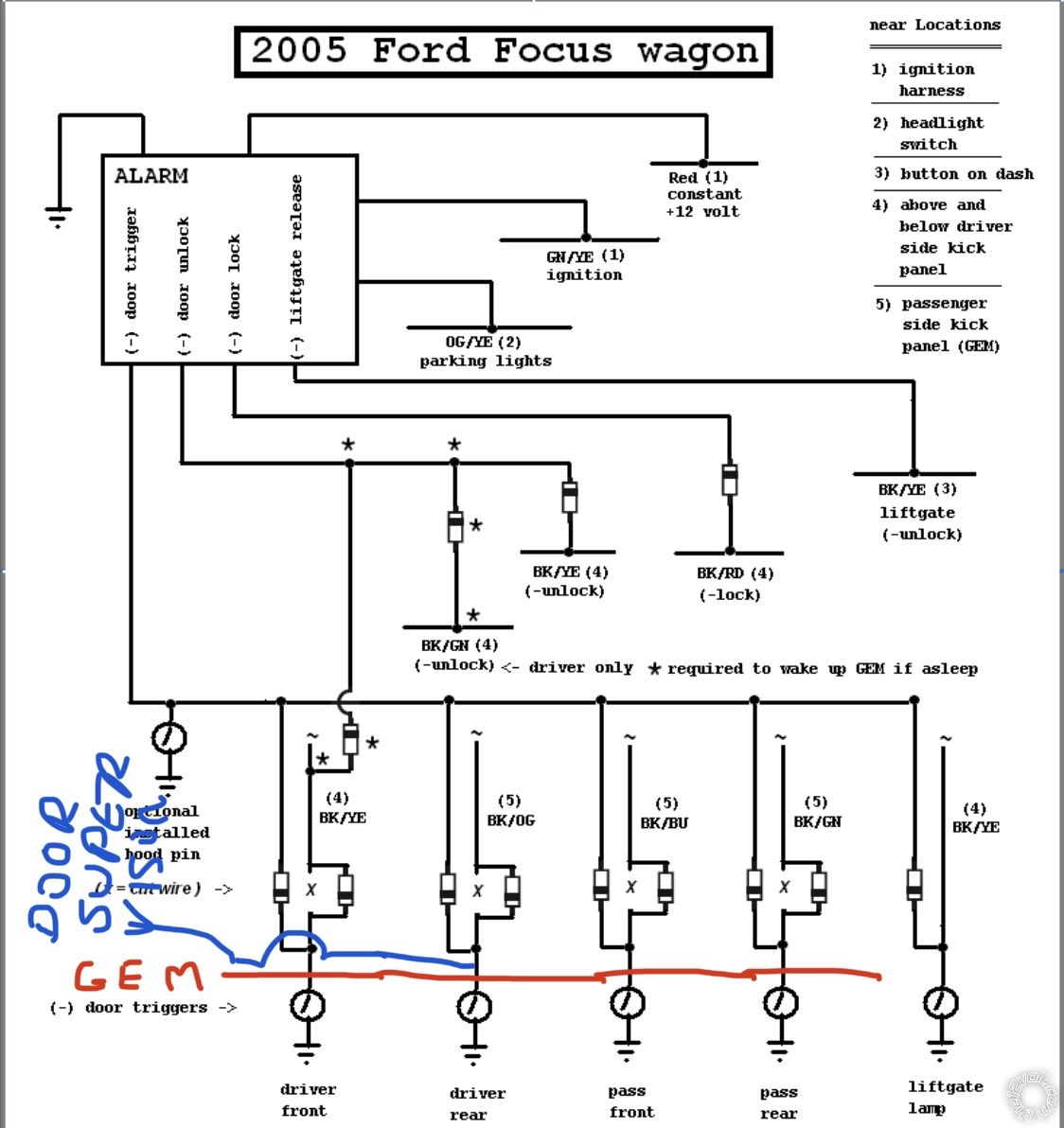
Posted By: kreg357
Date Posted: August 27, 2020 at 3:54 PM
1. Your wiring looks correct. Of course, you want to use a DMM on each ignition wire to verify it acts like the type of signal it's supposed to be. You could program the 5105 to Engine Checking Off and verify that the Crank Time is at the DefaULT (0.6 SEC ). With a R/S the Purple Starter wire should output a +12V signal for 0.6 seconds and stop. The engine may or may not start up if this time is too short but it won't continue cranking and it will prove something. Did you use a DMM to verify the Tach Signal. DMM to 20V AC, red lead to Tach source and Black lead to chassis ground. You should see a signal of around 1V that will rise slightly with additional RPM's.
3. If you are in Valet Mode the R/S function should work...
5. You could be right. The iDatastart diagrams only show the two Unlock wire connections.
6. Will the horn work via the steering column button? If yes, did the Black/Blue horn wire test as a (-) wire? Did you double check the connection? Did you test the 5105 to see if it is outputting a (-) Horn signal with a two press Lock?
7. Well, you can drop back 20 yards on this one. First lets discuss the diodes. The diodes placed in the run from the trigger wire to the 5105's single wire (-) Door Trigger Input are for isolation. The diodes placed in the cut Door Trigger wire going from the door switch to the GEM are to prevent 5105 false alarms. You can remove all the diodes for now and just concentrate on one Door Trigger wire. Lets work with the Drivers Door Trigger wire. That's all the 5105 needs to see to set and trigger an alarm condition. So with all the diodes removed and the cut wires reconnected, attach the 5105 Green input wire directly to the Black/Yellow Front Drivers door trigger wire (that was tested and verified) between the reconnected cut and the door pin switch. Lock the car with the 5105 and allow the alarm to set. Open the Drivers Door. The 5105 Brown Siren output wire should go to +12V. The Parking Lights should flash. If that works properly, add the diode to the 5105 door trigger input wire, band towards the car/away from the 5105. Try the test again. If all is OK, add the diode to the Black/Yellow vehicle trigger wire at the previous cut with the band towards the door pin switch. Run the test again. If things are still working OK add the next door and test that door...
-------------
Soldering is fun!
Posted By: xesvuli420
Date Posted: August 29, 2020 at 2:58 PM
Ok I did the test on the tach wire. with engine running its around 8v, and seems to go DOWN as I rev. Half throttle took me down to 7v. Im guessing even though this wire is BLACK/YELLOW AND at the fuel rail, its not the correct tach wire? Im starting to have nightmares of BLACK/YELLOW snakes! lmao. Im gonna try and find one that increases with engine RPM as you stated.
Consider the parking lights fixed!
Ive also fixed a couple unrelated issues.
Now its time to find out whats up with the horn.
lmao Im trying to do the damn diodes last, not looking forward to that upside down headache.
Hope all is well, see ya soon!
Consider the parking lights fixed!
Ive also fixed a couple unrelated issues.
Now its time to find out whats up with the horn.
lmao Im trying to do the damn diodes last, not looking forward to that upside down headache.
Hope all is well, see ya soon!
Posted By: kreg357
Date Posted: August 29, 2020 at 3:16 PM
Be careful with the Horn wire. Ford has a bad habit of including them with the Air Bag wire harness ( yellow connectors ).
For the Tach, is that 7V AC? You want to set the DMM to AC for the Tach, everything is DC. You could go with Engine Checking = OFF and set a fixed crank time of 0.6 seconds just to test the continuous cranking condition.
-------------
Soldering is fun!
For the Tach, is that 7V AC? You want to set the DMM to AC for the Tach, everything is DC. You could go with Engine Checking = OFF and set a fixed crank time of 0.6 seconds just to test the continuous cranking condition.
-------------
Soldering is fun!
Posted By: xesvuli420
Date Posted: August 29, 2020 at 3:55 PM
Yea and guess what color every single one of the 5 clips on the GEM are..? YELLOW! For an hour I looked elsewhere for a GEM because I thought it was some type of airbag module. I will be super careful on this horn circuit!
No I mistakenly had it still in dc. I didnt catch it above. thought me something new today, I had no idea you used AC for anything but the ignition/charging systems. Neat! Lucky for me though, I just decided to hook the BLACK/ORANGE up to the R/S and see what happened. I don't know what in the heck the BLACK/YELLOW wire is, but it sure as doodie isnt for the remote start. As soon as I tied in the BLACK/ORANGE the remote start works PERFECTLY! Thank goodness, one of my bigger issues is now off the table.
Ok talk soon, back to work for the horn.. but I dont understand how it will work during alarm going off, but wont during setting... holding down the panic, or activating the shock sensor sets the thing to honking, how would this work if my tie in to the blue wire wasnt good?
Posted By: xesvuli420
Date Posted: August 29, 2020 at 5:24 PM
Ok Got a lot to report this time.
So I tore out all the diodes and did a quick check. Sure enough the door triggers are going TO the GEM not FROM it. I believe this confirms every single one of the trigger diodes were in fact backwards. Im going to take a smoke break and then I will reinstall them in the opposite orientation. Im hopeful this will take care of most of the the remaining problems. I'll let you know soon enough. Please allow me to put this here for the next guy so he can do it right the first time. Ill remove it if my hunch proves wrong.
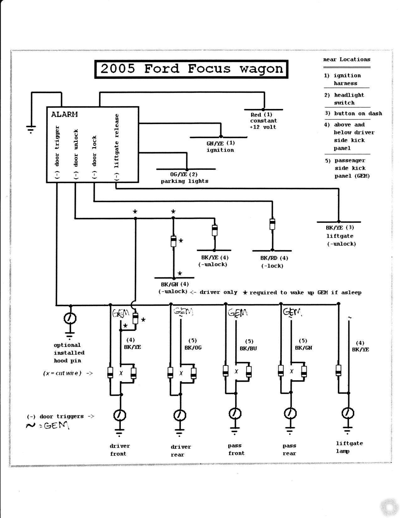
Also I believe the "door supervision" is working, but there does seem to be a tiny issue. The interior lights fade in and out from the factory, and apparently this is the same for when the supervision is alerting. unfortunately instead of the on/off/on/off I was hoping for, I get more of a dim/bright/dim/dark/dim/bright effect. It reminds me of when you have too much amplifier and no cap and the subwoofer hits. It honestly looks more like I am having electrical problems more than a intended effect lol. Anything I can do here? I'm afraid I'm limited to fords design.
ok well back to it. Ill hopefully have more good news soon!
So I tore out all the diodes and did a quick check. Sure enough the door triggers are going TO the GEM not FROM it. I believe this confirms every single one of the trigger diodes were in fact backwards. Im going to take a smoke break and then I will reinstall them in the opposite orientation. Im hopeful this will take care of most of the the remaining problems. I'll let you know soon enough. Please allow me to put this here for the next guy so he can do it right the first time. Ill remove it if my hunch proves wrong.
Also I believe the "door supervision" is working, but there does seem to be a tiny issue. The interior lights fade in and out from the factory, and apparently this is the same for when the supervision is alerting. unfortunately instead of the on/off/on/off I was hoping for, I get more of a dim/bright/dim/dark/dim/bright effect. It reminds me of when you have too much amplifier and no cap and the subwoofer hits. It honestly looks more like I am having electrical problems more than a intended effect lol. Anything I can do here? I'm afraid I'm limited to fords design.
ok well back to it. Ill hopefully have more good news soon!
Posted By: xesvuli420
Date Posted: August 30, 2020 at 12:40 PM
Ok at this point I think I have an evil spirit *ing with me.
Yesterday as I was reinstalling the diodes I decided to do the drivers door last for a few reasons. 1) I had to also tie in the unlock signal to it, and 2) thats the only door that was open (I was laying across the seats to rewire the trigger diodes), and I knew if it was the last wire I installed, and my theory was right about the diodes, when I install the last diode and touch the wires together, the interior light should finally come back on after days of not working, and triumphantly indicate a correct install. Im a goob, I know, but for me, its those moments that make you feel better about all the trouble that now finally has passed. Plus of course it means my hunch was right.
So as I had hoped for, as soon as the copper wires touched each other I got my door activated interior light back! I was so excited I immediately shut the doors and set the alarm. As you can probably guess it didnt before. When the alarm was set, opening and closing the doors had no effect on the armed alarm, or the interior light. I actually realized that the other day when I set the alarm off and "couldnt get it to stop" it was because of the shock sensor when i shut the door, not me triggering it with the door trigger. Anyways after I set the alarm I opened the door from the inside and it went off as it should! I checked every door, all doors were now communicating correctly with the Avital. Everything but the trunk trigger was working for the first time. I bet I armed and disarmed the unit ten times. I should also go ahead and mention the communication between the remote and the brain isnt the best. Quite often I have to hit the buttons twice to get it to register. Any of them, Lock, unlock, sometimes I will hit the button and nothing will happen. I dont know if im hitting the button too fast or whatever, more time will tell.
I still have 1 final undone wire... the dreaded trunk pin. I had considered leaving this undone since you cant open the trunk anyway without opening another door, or using the fob.. but since I had just had a major accomplishment, I was feeling thorough. I decided to re probe the BLACK/YELLOW wires in the drivers kick one last time in hopes of finding the right one. I even found 2 more to strip and check! I think that makes a total of 4 BLACK/YELLOW wires in the upper kick behind the fuses, 3 BLACK/YELLOW wires at the lower kick down on the actual floor under the carpet, and it doesnt look like any of them are the same, but Im gonna check them all. Sadly all of them were constant grounds. 12v at rest on the DMM. I didnt want to give up just yet so I went to the passenger side and thought I would check there as well. Good news! More BLACK/YELLOW wires. I think between the kick panel and under the carpet beside the seat there were 6 more wires that I tested. All with the same result. 12v at rest. I give up for now lol. She just isnt ready to be found.
Since the door triggers now work I can finally enter programming. I successfully initiated a tach learn. The first crank, the starter hung again, but the Avital cut itself off, re crunk and this time the starter disengaged as it was supposed to. It also stayed running which told me the Avital knew it didnt need to do the "3rd attempt" it is programmed to do if still unsuccessfully learned. I suppose this means the remote start side of the install is finally finished.
So finally, almost everything is working! All doors unlock and lock, the system arms and disarms, the doors trigger correctly. I am finally ready to clean out all the wire bits and electrical tape thats now insulating my floorboards. There have been quite a few other components installed aside from the Avital system so I'm excited to start putting the car back in order. I push all the carpet back and clean everything up. I'm going to keep the panels off for a few days just to be sure, but everything else gets cleaned and setup like before.
I take the car for a 5 mile victory lap. I still have a few more things to do to the car so I pull it back in the garage because Im ready to park it for the night, but just 1 more time lets see all that hard work paying off in action. I hit the R/S button, the car comes to life and starts, I hit it again, it dies. I hit the arm button and the car flashes and arms.. but I dont hear a clunk. I hit disarm, 2 flashes, no clunk. I go sit in the car and try again. more flashes, no clunks. Somehow someway the unlock/lock has now quit working. it still arms and disarms the Avital, but no locking or unlocking of any of the doors at all. I also notice the LED is blinking 3 times instead of its normal 2. It was like someone kicked the wind out of me. It was all working an hour ago, I hadn't even really worked on the drivers kick side. I was careful putting the carpet back in as well.. I tested the factory fob and it still locks and unlocks as expected. Defeated yet again, I grabbed a double and retired for the evening. How can 1 person be this unlucky?
I also want to bring up the horn. Yesterday I couldn't find a single issue from the Avital to the horn wire. I honestly dont know why this alarm will not honk the horn on a single press, on a double press, a triple, or even just keep pressing it over and over.. Never a horn honk. That being said, the button on the wheel works, the panic on both fobs work, and if you set the alarm off too. It works at every occasion except arming. Could it be in a silent mode?
So thats where we leave off for now, still incomplete. I pray that my remaining problems can be figured out quickly, maybe i'm in some kind off mode preventing the Avital from locking and unlocking the doors. That sounds silly to me, but 2 separate circuits are failing at the same time, even me knocking both the lock and unlock wires loose is jut too far fetched for me. Maybe all those arm and disarms with the door open before the test drive somehow programmed a problem. I'm not sure, all I know is for 20 minutes yesterday with the exception of the trunk pin, the install was working perfectly.
This is going to be the longest thread on this site before I can sign off on it being complete! lmao (but sadly)
I may try to enter programming today and play around. It may be helpful to reset the unit to factory if it has a way to do it.
Wish me luck please lol!
Posted By: kreg357
Date Posted: August 30, 2020 at 1:33 PM
No worries. If memory serves me the longest thread was 17 pages. :errr:
I would check to see if the the 3 pin Avital lock harness didn't get unseated with the final placement / adjustments to the 5105 brain.
For the Trunk Pin, I have a few sources that indicate a Black/Blue (-) in the DKP. Check in the trunk for the trunk light. That harness should have two wires. One is +12V constant and the other is the (-) trigger wire. You could extend the 5105 Trunk Pin wire to the trunk but finding it in the DKP would be easier.
Almost there.
-------------
Soldering is fun!
Posted By: wirewise
Date Posted: August 30, 2020 at 1:39 PM
kreg357 wrote:
No worries. If memory serves me the longest thread was 17 pages. :errr:...
Current record is 50 pages.
-------------
~wirewise~
Verify all wiring with your meter before making any connections!
Posted By: kreg357
Date Posted: August 30, 2020 at 1:54 PM
50 ! WOW ! I stand corrected.
For the Horn wire, with the lower steering column cover removed, there is a Black 9 Pin Plug centered under the middle of the column just to the right of the adjustment lever. The Black/Blue Horn wire is at Pin 6 and the only Black/Blue wire there. It is possible that the 5105, being an alarm system with a siren, does not use the horn like a regular RKE only system does. I'm not a big DEI person so perhaps another installer with more DEI experience can assist.
Also check Menu 1 Item 13. You might try setting it to Option 2 or 3. This will get horn outputs for other than Full Alarm conditions.
-------------
Soldering is fun!
Posted By: xesvuli420
Date Posted: August 30, 2020 at 2:22 PM
Man, I am about to throw in the towel. I dont know what to do.
I verified the plug was tight as it could be to the Avital, and I even checked for ground pulse at both connections AFTER the diodes. where it connects to the cars wires. Both get a momentary 12v signal when I hit the button. WHAT THE HELL HAPPENED?!? The Avital is pulsing the wires correctly, but they are doing nothing. Whats interesting to me is using the factory fob doesnt supply that same wire with a ground pulse. I dont understand what is going on here.
On the horn, I'm tied in to the wire youre referencing. It works, just doesn't chirp for arming or setting the menu options. I can confirm this is not correct as we have an Avital system on our other car. It is supposed to be honking for arming and menu selections. I also went into programming to make sure it was set to ON. I also went ahead and set the options for unlock to double pulse.. if i ever get the thing to work again. How can it honk for all the other stuff, but not chirps?!?
EDIT
We now have horn. Apparently you ae correct, by default the horn honk is only for full alarm. Changing that setting got us horn at every event as we are supposed to. Thank you for that.
Oh and hello wirewise! welcome to the doodie show lol.
Posted By: kreg357
Date Posted: August 30, 2020 at 3:30 PM
Double check your main Avital Chassis Ground connection. I always solder on a terminal ring and connect to solid chassis metal frame.
Guess you could start checking Focus fuses but if the factory FOB and door buttons work the locks, I kinda doubt that's the issue.
Perhaps the big reset is worth a try. Disconnect the negative lead on the car battery for 10 minutes. When you reconnect the battery, expect the Avital alarm to go off so be ready with the Avital FOB with an unlock. Maybe the GEM or BCM needs a reset.
-------------
Soldering is fun!
Posted By: xesvuli420
Date Posted: August 30, 2020 at 3:31 PM
So I found out that the door lock/unlock buttons, and the trunk pop button no longer works. That means most likely its not my loose wires that are the problem. Getting excited that this sounds like a blown fuse I researched the location of the power lock fuse. of course its the only one hidden on the back of the fuse box. It took me 20 minutes to get the fuse box out only to find the fuse wasn't blown. I wouldve bet a lot money that was my problem. I could cry now if my head wasnt already hurting. I'm taking another break.. I cant handle this level of aggravation lol.
Posted By: xesvuli420
Date Posted: August 30, 2020 at 5:46 PM
ITS OVER!!!

I guess we wont get to 50 pages after all. Thanks to god I finally found the issue to be a poorly seated GEM plug. The inside locks as well as the Avitals locking capabilities have been restored.
My 1st remote start install is officially completed!
I cant thank you enough for being a such a guiding light through this install from the very first post to the very last. Youve been there every step of the way to try and help and I can't express how humbled I am by your decision to keep coming back in here and checking on me. Im grateful for the kindness you've shown me. It has allowed me to take on a challenging and exciting opportunity to learn something new. I'm totally ramped up to do it again and see how much better my 2nd time will be in my truck... but maybe after a week or two of mental hibernation lol. I hope one day I can help someone as diligently as you have helped me. I am in your debts sir.
:D :D :D :D :D :D :D :D :D :D :D :D :D :D :D :D :D :D :D :D :D :D :D :D :D :D :D :D :D :D :D :D :D :D :D :D :D :D :D :D :D :D :D :D :D :D :D :D :D :D :D :D :D :D :D :D :D :D :D :D
Posted By: kreg357
Date Posted: August 30, 2020 at 7:10 PM
Congratulations! You researched, learned, planned and stuck to the task. Every car is different and that gen Focus isn't the easiest as a first install. You found out that Directed install guides are hard to find, use a lot of insider terms and assume that you've been to their Pit Training schools. The next one will be easier. Enjoy your new and improved Focus!
-------------
Soldering is fun!
-------------
Soldering is fun!