Viper160xv, Check Engine Light, 2000 Chevrolet Silverado
Printed From: the12volt.com
Forum Name: Car Security and Convenience
Forum Discription: Car Alarms, Keyless Entries, Remote Starters, Immobilizer Bypasses, Sensors, Door Locks, Window Modules, Heated Mirrors, Heated Seats, etc.
URL: https://www.the12volt.com/installbay/forum_posts.asp?tid=146572
Printed Date: May 14, 2026 at 7:32 AM
Topic: Viper160xv, Check Engine Light, 2000 Chevrolet Silverado
Posted By: wittler
Subject: Viper160xv, Check Engine Light, 2000 Chevrolet Silverado
Date Posted: November 24, 2020 at 9:05 AM
Installed a viper160xv in my 2000 Silverado and works good But have an issue with when I used remote start and went to drive it my cel came on and transmission was not shifting properly. But if I deactivate it and the start it with the key it works fine after I cleared cel witch said random misfire. Any thoughts on this problem?
-------------
Ralph
Replies:
Posted By: kreg357
Date Posted: November 24, 2020 at 10:44 AM
You probably neglected to power the White IGN2 wire from the Viper. Both IGN1 and IGN2 need power during a R/S.
-------------
Soldering is fun!
Posted By: chev104275
Date Posted: November 24, 2020 at 12:31 PM
You need to power both IGNs as Kreg said
IGNITION 1 PINK (+) @ IGNITION SWITCH HARNESS
IGNITION 2 WHITE (+), SEE NOTE #2 @ IGNITION SWITCH HARNESS
NOTE #2: The IGNITION #2 wire WHITE must be connected to prevent a CHECK ENGINE LIGHT from turning on and to prevent DAMAGE to the TRANSMISSION on this Vehicle.
-------------
If i Can't Install it I Don't need it Joe
Posted By: wittler
Date Posted: November 25, 2020 at 6:20 AM
Pink/white wire is connected to white wire I will check that it is getting power Thanks
-------------
Ralph
Posted By: wittler
Date Posted: November 26, 2020 at 10:10 AM
Checked for power at pink/white wire from R/S when activated and have nothing
-------------
Ralph
Posted By: kreg357
Date Posted: November 26, 2020 at 11:48 AM
Did you connect the thick Red/White wire to +12V constant power? If yes, is the 30 amp fuse OK?
-------------
Soldering is fun!
Posted By: wittler
Date Posted: November 26, 2020 at 2:00 PM
Yes have power to both heavy red wires fuses good. Power comes out on ignition 1 but not 2. Wondering if the relay module is not working properly 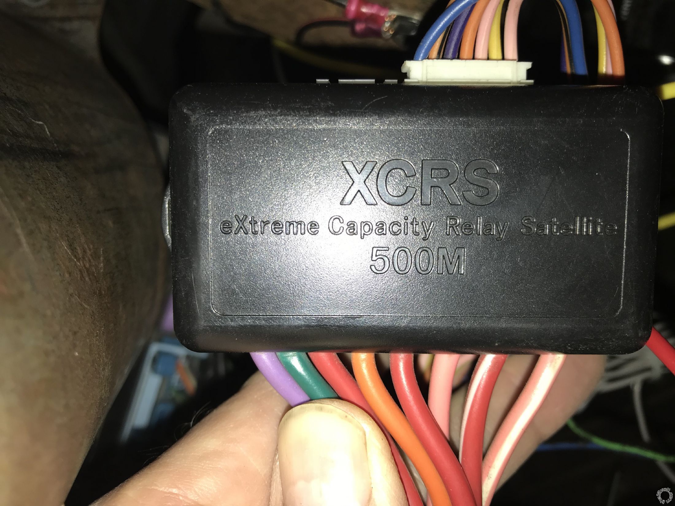 ------------- Ralph
Posted By: kreg357
Date Posted: November 26, 2020 at 4:12 PM
There might be three +12V input power wires, Red, Red and Red/White. All three must have +12V constant.
-------------
Soldering is fun!
Posted By: wittler
Date Posted: November 26, 2020 at 8:49 PM
Here is pic of heavy wires all red and the red/white have power.
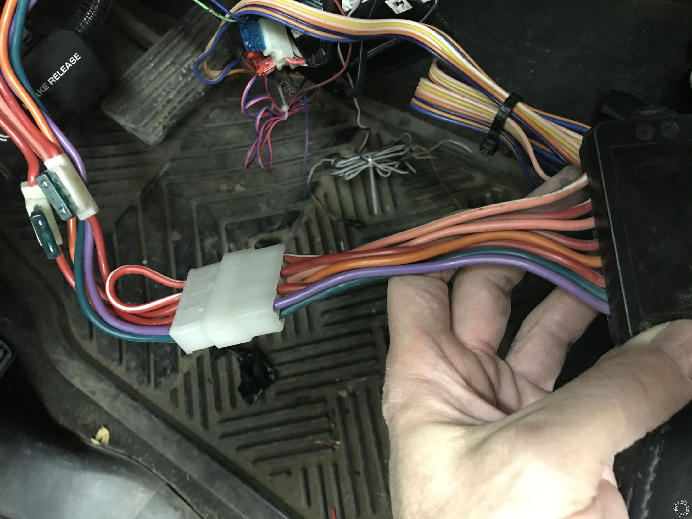 ------------- Ralph
Posted By: wittler
Date Posted: November 27, 2020 at 8:16 AM
How could I test that this relay module is getting a signal to turn on ignition 2? Would I check for - 200ma signal on pink/white small wire on ribbon coming from the main unit?
-------------
Ralph
Posted By: geepherder
Date Posted: November 27, 2020 at 9:02 AM
That's what I would do.
-------------
My ex once told me I have a perfect face for radio.
Posted By: wittler
Date Posted: November 27, 2020 at 12:02 PM
Checked for signal from main box to relay , ignition 1 yes, ignition 2 no signal checked programmed setting to make sure it was set for ignition or acc and it is correct so thinking the main box is problem. Any work around like connect ignition 1& 2 together before relay?
-------------
Ralph
Posted By: geepherder
Date Posted: November 27, 2020 at 3:14 PM
While that may work, your system should have a separate 4-pin remote start auxiliary harness, with a negative ignition output. I'd use that to trigger a relay. You could try jumping that to the small pink/white in the ribbon harness, or just use your own separate relay.
Since the negative outputs are only rated at 200 mA, one relay coil can draw nearly that while the engine is running. If you were to try running a second one with the same output, it could fry.
-------------
My ex once told me I have a perfect face for radio.
Posted By: wittler
Date Posted: November 27, 2020 at 3:20 PM
Ok thanks for the information Ill try 4 pin connector
-------------
Ralph
Posted By: davep.
Date Posted: November 28, 2020 at 11:39 AM
The "separate 4-pin remote aux harness" that geepherder (who I respect) mentions is on the Relay Satellite, not on the main module. (I can see the 4-pin receptacle in your pic of the satellite, and I remember that's where it was on one of my installs). Here's what I would do / check:
Set up your volt meter to monitor voltage on the large pink/white wire. In a quiet environment, ground the small pink/wht trigger wire to ground by back-probing the terminal with a paperclip jumped to ground. If the Large pink/white powers-up, the trigger in the module is faulty. I would de-pin the small pink/wht from the module, and piggy-back it onto the pink IGN output. Use the IGN trigger for both IGN 1 and IGN 2.
If the above does not power-up the large pink/wht: Set up your volt meter to monitor the small pink wht. Red lead on a +12 Volt source, and the Black lead on the small pink/wht. The meter should read nominal 0-Volts. Remote start the truck. If the meter indicates +12V, the trigger is functioning, it can be concluded that the relay in the satellite is bad. Use the trigger to control an external relay for your IGN 2.
The predecessor to the "Satellite Relay" was a group of 4 regular relays. Two of these were triggered by one output of the module. The relay coils in the large relays are about 125Ma, so the total load exceeded the "200Ma Max", but that's how DEI did it on the 551T which they sold a gillion of. I don't know what the tiny relays in the satellite draw, but I'm sure it is less than 125Ma. I have had a dual-relay install in my DD pick-up for 6 years. I cycle the RS about 15-25 times a week. The module is still fine, so I don't feel the "2 relays on a single output" is harmful.
There's a little more info for you. It may help.
|