2001 Jeep Cherokee, Viper 5806V
Printed From: the12volt.comForum Name: Car Security and Convenience
Forum Discription: Car Alarms, Keyless Entries, Remote Starters, Immobilizer Bypasses, Sensors, Door Locks, Window Modules, Heated Mirrors, Heated Seats, etc.
URL: https://www.the12volt.com/installbay/forum_posts.asp?tid=146702
Printed Date: April 14, 2026 at 9:31 PM
Topic: 2001 Jeep Cherokee, Viper 5806V
Posted By: firefighter1466
Subject: 2001 Jeep Cherokee, Viper 5806V
Date Posted: January 30, 2021 at 8:36 PM
So - as a newbie to wiring remote starts, it looks like I chose the most feature rich remote start to put on the featureless 01 Jeep Cherokee XJ. Hoping I can gain some insight here, as it looks like there's a ton of members on here who are highly skilled based on several of the posts I've read through over the last few days.
I'm really trying to understand Viper's diagrams and instructions and compare it to the few simple things that a Jeep Cherokee XJ has the capability of accepting. I feel there's a lot here I cannot use, but I want to use it to the max and not miss anything.
So I'll post what I have in the instructions, and what I've understood it should be matched up to based on the diagram/notes posted here in the notes. Anything in brackets would be my questions or comments on what I believe to be correct.
Main Harness, 6-pin connector
Red (+) 12VDC Constant Input - Should be: Constant +12 Volts: RED OR PINK/BLACK IGNITION SWITCH HARNESS?
Black (-) Chassis Ground - I don't see a ground in the harness, (again I'm a noob), I would assume I just ground it to the frame?
Brown (+) Siren Output - I would imagine this connects to the Siren that was included, "Directed 514L Soft-Chirp Siren", though I'm assuming it's either the red wire and the black would be grounded? There are only two wires coming out of this thing
White/Brown Parking Light Isolation Wire - #87A N/C of onboard relay - I don't see anything on the diagram about an isolation wire
White Parking Light Output - #30 Common of onboard relay - Parking Lights: BLACK / YELLOW AT HEADLIGHT SWITCH?
Orange (-) 500mA GWA (Ground When Armed Output) - Again.. I'm confused
Door Lock, 3-pin connector
Blue (-) 500mA Unlock Output - Power Unlock: PINK/VIOLET (+) LOCATED IN DRIVER'S KICK PANEL *
EMPTY
Green (-) 500mA Lock Output - Power Lock: ORANGE / VIOLET (+) LOCATED IN DRIVER'S KICK PANEL *
Auxiliary/Shutdown/Trigger Harness, 24-pin connector
Pink/White (-) 200mA Ignition 2 - Flex Relay Output - Ignition #2: BLACK/ ORANGE IGNITION SWITCH HARNESS??
Blue/White (-) 200mA 2nd Status/Rear Defogger Output - Unused?
Red/White (-) 200mA Trunk Release Output - Trunk Release: PINK/BLACK (+) (LIFTGATE UNLOCK)??
Black/Yellow (-) 200mA Dome Light Output - Dome Lights/Superv: YELLOW (-) AT ANY PIN SWITCH
Dark Blue (-) 200mA Status Output - Unused?
White/Black (-) 200mA Aux 3 Output - Unused?
White/Violet (-) 200mA Aux 1 Output - Unused?
Orange/Black (-) 200mA Aux 4 Output - Unused?
Gray (-) Hood Pin Input (N/C or N/O) - Unused?
Blue (-) Trunk Pin/Instant Trigger Input (N/C or N/O) - Unused?
White/Blue Activation Input - Unused?
Violet/White* Tachometer Input - Tach Signal: GRAY AT COIL ON PASSENGER SIDE OF ENGINE (* Notes required for manual transmission - is there any reason to mess with this wire if it's an automatic?)
Black/White** (-) Parking/E-Brake Input - I would imagine this is wired directly to the parking brake somehow, any notes on this?
Green/Black (-) 200mA Factory Alarm Disarm Output - OEM Alarm Disarm: VIOLET / YELLOW (-) DRIVER'S KICK PANEL
Green* (-) Door Input - Also labeled as manual transmission requirement - do I need?
Brown/Black (-) 200mA Horn Honk Output - OEM Horn: BLACK/ RED (-) STEERING COLUMN HARNESS??
Pink (-) 200mA Ignition 1 Output - ?
Violet* (+) Door Input - Again, manual transmission? Do I need this?
Violet/Black (-) 200mA Aux 2 Output - ?
Brown (+) Brake Shutdown Input - ?
Violet/Yellow (-) 200mA Starter Output - ?
Gray/Black (-) Diesel Wait To Start Input - Easy to guess that this one isn't applicable
Orange (-) 200mA Accessory Output - ?
Green/White (-) 200mA Factory Alarm Arm Output - OEM Alarm Arm: ARMS WHEN DOORS ARE LOCKED WITH DR. DOOR OPEN
Remote Start, 10-pin heavy gauge connector
No Connection
Red/Black (+) Fused 12V Accessory/Starter Input - Accessory: BLACK/ WHITE IGNITION SWITCH HARNESS??
Pink/Black (+) Flex Relay Input #87A N/C* key side of flex relay (if required) - Unused?
Pink/White (+) Ignition 2 / - #30 Common of flex relay - Ignition #2: BLACK/ ORANGE IGNITION SWITCH HARNESS??
Red (+) Fused 12V Ignition 1 Input - Ignition +12 Volts: D BLUE IGNITION SWITCH HARNESS??
Green (+) Starter Input (Key side of the failsafe starter disable) - Not sure what it means by failsafe starter disable
Violet (+) Starter Output (Car side of the failsafe starter disable) - Same as above
Orange (+) Accessory Output - Not sure if this should be the black/white as listed above, I only found one accessory noted. Which would be input/output?
Red/White (+) Fused 12V Input, Ignition 2 - #87 N/O* - Flex Relay Input - Ignition #2 was used above, now I'm getting more and more confused
Pink (+) Ignition 1 Input/Output - Ignition 1 was used above as well.. this is harder than it looks
Sorry - you guys probably aren't used to getting someone as much of a noob as me. I'm trying to learn but I think I'm in way over my head..
-------------
Jon
Replies:
Posted By: kreg357
Date Posted: January 31, 2021 at 9:59 AM
It's good that you are making an effort to learn from this install. As you are finding out there is a big learning curve here. You are also realizing that as a DIYer your options for tech support from the A/S manufacturer is about nil.
Yes indeed, the system you have chosen is feature rich. It was made to handle many situations and vehicles. Your basic Jeep won't need much of the Vipers available features. But it is a good, solid unit that can handle all of your Jeeps requirements.
The Install Guide that come with your system is a very simplified 2 page document intended for a Viper trained dealer. To get you started with the Viper system, review this older guide from a similar Viper system. While it is out of date, it does contain a lot of the info missing from the current install guides with a better description of each wires needs and function. You will notice that many of the Wire Names, Wire Colors and Wire functions have remained the same over the years. https://www.the12volt.com/installbay/file.asp?ID=710
A few questions... What color key head do you have? A black head means no Transponder Immobilizer system and a Gray head indicates a Transponder Immobilizer system and the need for a bypass module. Do you have power door locks?
The next step is to locate several wire listing guides for your vehicle. These will be an aid in locating the necessary wires. This site has some info as listed below :
https://www.the12volt.com/installbay/alarmdetail/1214.html
https://www.the12volt.com/installbay/forum_posts.asp?tid=1115
Here is the info from Bulldog Security : https://www.bulldogsecurity.com/bdnew/vehiclewiringdiagrams.aspx
You can use this info to make up a wire chart for your vehicle and the needed Viper connections. The main thing to understand is the (-) and (+) notation in the wire lists and the in the Viper wire diagram. We can use the Power Lock wires as an example. In the available wire lists, it indicates that the power locks need a (-) signal but you show a (+) in your chart. With the 5806V diagram, it shows a (-) lock output. You should use a DMM to verify that the Jeep has a Type B (-) lock system, update your chart and understand that a direct connect connection from the Vipers (-) Lock wires to the Jeeps (-) lock wires is all that is required.
This will get you going. You can update your chart and ask questions as you go along. Read up on the Vipers Programming Options, as some will need to be changed to support your Jeep.
-------------
Soldering is fun!
Posted By: firefighter1466
Date Posted: January 31, 2021 at 10:04 AM
Thanks for the quick response! I will start reviewing all of this information you provided. I just finished tearing out the dash to replace the heater core, and before putting all the physical covers back up I wanted to take this time to install the remote start with everything out in the open.
To answer your questions: I have a black key. I am the 2nd owner of this Jeep so I'm not sure if it's the ORIGINAL key or a replacement, but in either instance it's black. I really need to fix the steering column, but right now I can crank it and pull the key out lock the doors and walk away and it will remain cranked and even allow someone to drive it if I unlock it without the key nearby. So I would imagine there is no Immobilizer system installed (gray key). I DO have power locks.
Also - I tried opening "https://www.the12volt.com/installbay/file.asp?ID=710", but it does not work, it takes me to the downloads page where I would need to find one to download.
EDIT: I am trying to understand the - and + as you mentioned, but something just isn't clicking. While I was reviewing the 2001 information on your 2nd link (the one that I had already been reviewing) it shows (+) next to lock and unlock, while the 2000 Jeep Cherokee post shows (-) for the unlock and lock. I'm not sure what to make of this.
-------------
Jon
Posted By: kreg357
Date Posted: January 31, 2021 at 10:33 AM
The Viper link to the older install guide is for a Viper 5701 system, so search on that in the Downloads section. The wire descriptions are more detailed.
Yes, Black key means no immobilizer system and no need for a bypass module. Any plain hardware store key will work in your Jeep. This will save you some time and money.
First "gotcha" moment is finding discrepancies in the wire guides. It happens all the time. That's why using a Digital Multi Meter and verifying each vehicle wire is so important. I'm pretty sure that Jeep has Type B (-) locks. Another gotcha is that to test these lock wires in your Jeep, the doors must be closed. Additionally, the Vipers (-) 500mA lock output may not be strong enough to actuate the lock solenoids so external relays might be required. And finally, to test for (-) signals using a DMM, set the DMM to 20VDC, connect the Red test lead to +12V constant and the Black Test lead to the suspect wire. The DMM will show a (+)12V pulse with a lock signal.
-------------
Soldering is fun!
Posted By: firefighter1466
Date Posted: January 31, 2021 at 11:24 AM
So any of these that I need to test for a (-) if I get a positive 12v it means its a (-) ?
-------------
Jon
-------------
Jon
Posted By: kreg357
Date Posted: January 31, 2021 at 11:48 AM
firefighter1466 wrote:Yes, kinda inverse logic but the only way to test for a (-) signal. Basically the DMM Red lead is on the battery positive terminal and when the Black lead gets a chassis ground present, the DMM's circuit is completed and the DMM shows the battery voltage. You are doing the same thing in reverse for (+) signals. In that vehicle the Parking Lights are listed as a (+) signal. You set the DMM to 20VDC, connect the Black test lead to chassis ground and the Red test lead to the BLACK/YELLOW suspect wire. The DMM shows 0V with the Parking Lights off. When you turn the Parking Lights ON, the BLACK/YELLOW wire goes to +12V, the DMM Red lead sees this +12V and the DMM circuit is complete and the DMM reads +12V. This will be the same for the Jeeps ignition wires.
So any of these that I need to test for a (-) if I get a positive 12v it means its a (-) ?
-------------
Soldering is fun!
Posted By: firefighter1466
Date Posted: January 31, 2021 at 11:56 AM
Thanks kreg357,
I guess I'm still overwhelmed by the sheer number of wires that the Viper system has available. Is there an easy way to determine what all needs to be hooked up for this model Jeep so that I can kind of cross the others out and not worry about them?
-------------
Jon
I guess I'm still overwhelmed by the sheer number of wires that the Viper system has available. Is there an easy way to determine what all needs to be hooked up for this model Jeep so that I can kind of cross the others out and not worry about them?
-------------
Jon
Posted By: kreg357
Date Posted: January 31, 2021 at 12:33 PM
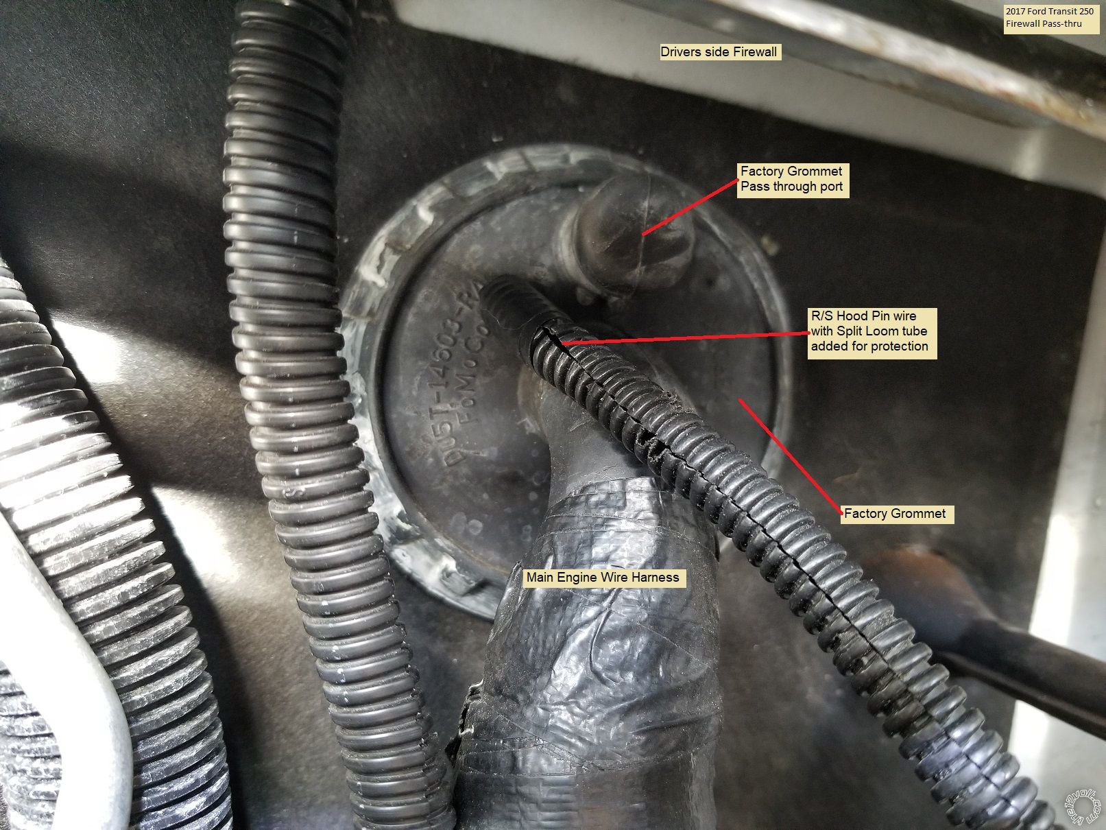
A basic R/S w/Keyless and alarm will need...
These are the Jeep wires you need :
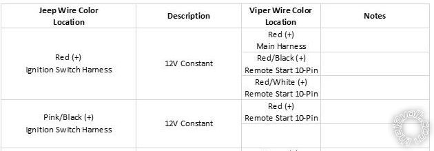
12 VOLT CONSTANT PINK/BLACK (+) and RED (+) IGNITION SWITCH HARNESS
STARTER YELLOW (+) IGNITION SWITCH HARNESS
IGNITION 1 DARK BLUE (+) IGNITION SWITCH HARNESS
IGNITION 2 BLACK/ORANGE (+) IGNITION SWITCH HARNESS
ACCESSORY/HEATER BLOWER 1 BLACK/WHITE (+) IGNITION SWITCH HARNESS
PARKING LIGHTS ( + ) BLACK/YELLOW (+) @ HEADLIGHT SWITCH
POWER LOCK ORANGE/PURPLE (TYPE B) IN DRIVERS KICK PANEL
POWER UNLOCK PINK/PURPLE (TYPE B) IN DRIVERS KICK PANEL
DOOR TRIGGER YELLOW (-) IN DRIVERS KICK PANEL or HEADLIGHT SWITCH
TACH GRAY @ PCM, BLACK Plug
BRAKE WHITE/TAN (+) @ SWITCH ABOVE BRAKE PEDAL
Rear Defrost DARK BLUE/WHITE (-) AT DEFOGGER SWITCH
On the Viper side, you need :
Main Harness, 6-pin connector
Red (+) 12VDC Constant Input - Should be: Constant +12 Volts: RED OR PINK/BLACK IGNITION SWITCH HARNESS
Black (-) Chassis Ground - I would just ground it to clean, paint and rust free frame
Brown (+) Siren Output - I would imagine this connects to the Siren that was included, "Directed 514L Soft-Chirp Siren", red wire. Black siren wire to chassis ground.
White/Brown Parking Light Isolation Wire - not used
White Parking Light Output - #30 Common of onboard relay - Parking Lights: BLACK / YELLOW AT HEADLIGHT SWITCH. Set Viper fuse jumper to (+)
Orange (-) 500mA GWA (Ground When Armed Output) - not used
Door Lock, 3-pin connector
Blue (-) 500mA Unlock Output - Power Unlock: PINK/VIOLET (-) LOCATED IN DRIVER'S KICK PANEL
EMPTY
Green (-) 500mA Lock Output - Power Lock: ORANGE / VIOLET (-) LOCATED IN DRIVER'S KICK PANEL
Auxiliary/Shutdown/Trigger Harness, 24-pin connector
Pink/White (-) 200mA Ignition 2 - Flex Relay Output - Ignition #2: not used
Blue/White (-) 200mA 2nd Status/Rear Defogger Output - could use for rear defrost - optional
Red/White (-) 200mA Trunk Release Output - Trunk Release: PINK/BLACK (+) (LIFTGATE UNLOCK)?? not sure, unlocks with doors?
Black/Yellow (-) 200mA Dome Light Output - Dome Lights/Superv: YELLOW (-) AT ANY PIN SWITCH
Dark Blue (-) 200mA Status Output - Unused
White/Black (-) 200mA Aux 3 Output - Unused
White/Violet (-) 200mA Aux 1 Output - Unused
Orange/Black (-) 200mA Aux 4 Output - Unused
Gray (-) Hood Pin Input (N/C or N/O) - connect to kit supplied hood pin switch you installed
Blue (-) Trunk Pin/Instant Trigger Input (N/C or N/O) - Unused
White/Blue Activation Input - Unused
Violet/White* Tachometer Input - Tach Signal: GRAY AT COIL ON PASSENGER SIDE OF ENGINE *
Black/White** (-) Parking/E-Brake Input - not needed for auto trans - connect to chassis ground
Green/Black (-) 200mA Factory Alarm Disarm Output - OEM Alarm Disarm: VIOLET / YELLOW (-) DRIVER'S KICK PANEL does your Jeep have the factory alarm?
Green* (-) Door Input - YELLOW (-) IN DRIVERS KICK PANE - do I need? Yes, for Viper alarm functions
Brown/Black (-) 200mA Horn Honk Output - OEM Horn: BLACK/ RED (-) STEERING COLUMN HARNESS - optional - you have siren
Pink (-) 200mA Ignition 1 Output - not used
Violet* (+) Door Input - Do I need this? no, using (-) Door trigger
Violet/Black (-) 200mA Aux 2 Output - not used
Brown (+) Brake Shutdown Input - WHITE/TAN (+) @ SWITCH ABOVE BRAKE PEDAL
Violet/Yellow (-) 200mA Starter Output - not used
Gray/Black (-) Diesel Wait To Start Input - Easy to guess that this one isn't applicable
Orange (-) 200mA Accessory Output - not used
Green/White (-) 200mA Factory Alarm Arm Output - OEM Alarm Arm: ARMS WHEN DOORS ARE LOCKED WITH DR. DOOR OPEN does your Jeep have the factory alarm?
Remote Start, 10-pin heavy gauge connector
No Connection
Red/Black (+) Fused 12V Accessory/Starter Input - RED (+) IGNITION SWITCH HARNESS
Pink/Black (+) Flex Relay Input #87A N/C* key side of flex relay (if required) - Unused
Pink/White (+) Ignition 2 / - #30 Common of flex relay - Ignition #2: BLACK/ ORANGE IGNITION SWITCH HARNESS
Red (+) Fused 12V Ignition 1 Input - Ignition +12 Volts: PINK/BLACK (+) IGNITION SWITCH HARNESS
Green (+) Starter Input (KEY SIDE of the failsafe starter disable) - cut YELLOW (+) IGNITION SWITCH HARNESS - key side
Violet (+) Starter Output (CAR SIDE of the failsafe starter disable) - cut YELLOW (+) IGNITION SWITCH HARNESS - vehicle side
Orange (+) Accessory Output - BLACK/WHITE (+) IGNITION SWITCH HARNESS
Red/White (+) Fused 12V Input, Ignition 2 - #87 N/O* - Flex Relay Input - RED (+) IGNITION SWITCH HARNESS
Pink (+) Ignition 1 Input/Output - Ignition 1 DARK BLUE (+) IGNITION SWITCH HARNESS
-------------
Soldering is fun!
These are the Jeep wires you need :
12 VOLT CONSTANT PINK/BLACK (+) and RED (+) IGNITION SWITCH HARNESS
STARTER YELLOW (+) IGNITION SWITCH HARNESS
IGNITION 1 DARK BLUE (+) IGNITION SWITCH HARNESS
IGNITION 2 BLACK/ORANGE (+) IGNITION SWITCH HARNESS
ACCESSORY/HEATER BLOWER 1 BLACK/WHITE (+) IGNITION SWITCH HARNESS
PARKING LIGHTS ( + ) BLACK/YELLOW (+) @ HEADLIGHT SWITCH
POWER LOCK ORANGE/PURPLE (TYPE B) IN DRIVERS KICK PANEL
POWER UNLOCK PINK/PURPLE (TYPE B) IN DRIVERS KICK PANEL
DOOR TRIGGER YELLOW (-) IN DRIVERS KICK PANEL or HEADLIGHT SWITCH
TACH GRAY @ PCM, BLACK Plug
BRAKE WHITE/TAN (+) @ SWITCH ABOVE BRAKE PEDAL
Rear Defrost DARK BLUE/WHITE (-) AT DEFOGGER SWITCH
On the Viper side, you need :
Main Harness, 6-pin connector
Red (+) 12VDC Constant Input - Should be: Constant +12 Volts: RED OR PINK/BLACK IGNITION SWITCH HARNESS
Black (-) Chassis Ground - I would just ground it to clean, paint and rust free frame
Brown (+) Siren Output - I would imagine this connects to the Siren that was included, "Directed 514L Soft-Chirp Siren", red wire. Black siren wire to chassis ground.
White/Brown Parking Light Isolation Wire - not used
White Parking Light Output - #30 Common of onboard relay - Parking Lights: BLACK / YELLOW AT HEADLIGHT SWITCH. Set Viper fuse jumper to (+)
Orange (-) 500mA GWA (Ground When Armed Output) - not used
Door Lock, 3-pin connector
Blue (-) 500mA Unlock Output - Power Unlock: PINK/VIOLET (-) LOCATED IN DRIVER'S KICK PANEL
EMPTY
Green (-) 500mA Lock Output - Power Lock: ORANGE / VIOLET (-) LOCATED IN DRIVER'S KICK PANEL
Auxiliary/Shutdown/Trigger Harness, 24-pin connector
Pink/White (-) 200mA Ignition 2 - Flex Relay Output - Ignition #2: not used
Blue/White (-) 200mA 2nd Status/Rear Defogger Output - could use for rear defrost - optional
Red/White (-) 200mA Trunk Release Output - Trunk Release: PINK/BLACK (+) (LIFTGATE UNLOCK)?? not sure, unlocks with doors?
Black/Yellow (-) 200mA Dome Light Output - Dome Lights/Superv: YELLOW (-) AT ANY PIN SWITCH
Dark Blue (-) 200mA Status Output - Unused
White/Black (-) 200mA Aux 3 Output - Unused
White/Violet (-) 200mA Aux 1 Output - Unused
Orange/Black (-) 200mA Aux 4 Output - Unused
Gray (-) Hood Pin Input (N/C or N/O) - connect to kit supplied hood pin switch you installed
Blue (-) Trunk Pin/Instant Trigger Input (N/C or N/O) - Unused
White/Blue Activation Input - Unused
Violet/White* Tachometer Input - Tach Signal: GRAY AT COIL ON PASSENGER SIDE OF ENGINE *
Black/White** (-) Parking/E-Brake Input - not needed for auto trans - connect to chassis ground
Green/Black (-) 200mA Factory Alarm Disarm Output - OEM Alarm Disarm: VIOLET / YELLOW (-) DRIVER'S KICK PANEL does your Jeep have the factory alarm?
Green* (-) Door Input - YELLOW (-) IN DRIVERS KICK PANE - do I need? Yes, for Viper alarm functions
Brown/Black (-) 200mA Horn Honk Output - OEM Horn: BLACK/ RED (-) STEERING COLUMN HARNESS - optional - you have siren
Pink (-) 200mA Ignition 1 Output - not used
Violet* (+) Door Input - Do I need this? no, using (-) Door trigger
Violet/Black (-) 200mA Aux 2 Output - not used
Brown (+) Brake Shutdown Input - WHITE/TAN (+) @ SWITCH ABOVE BRAKE PEDAL
Violet/Yellow (-) 200mA Starter Output - not used
Gray/Black (-) Diesel Wait To Start Input - Easy to guess that this one isn't applicable
Orange (-) 200mA Accessory Output - not used
Green/White (-) 200mA Factory Alarm Arm Output - OEM Alarm Arm: ARMS WHEN DOORS ARE LOCKED WITH DR. DOOR OPEN does your Jeep have the factory alarm?
Remote Start, 10-pin heavy gauge connector
No Connection
Red/Black (+) Fused 12V Accessory/Starter Input - RED (+) IGNITION SWITCH HARNESS
Pink/Black (+) Flex Relay Input #87A N/C* key side of flex relay (if required) - Unused
Pink/White (+) Ignition 2 / - #30 Common of flex relay - Ignition #2: BLACK/ ORANGE IGNITION SWITCH HARNESS
Red (+) Fused 12V Ignition 1 Input - Ignition +12 Volts: PINK/BLACK (+) IGNITION SWITCH HARNESS
Green (+) Starter Input (KEY SIDE of the failsafe starter disable) - cut YELLOW (+) IGNITION SWITCH HARNESS - key side
Violet (+) Starter Output (CAR SIDE of the failsafe starter disable) - cut YELLOW (+) IGNITION SWITCH HARNESS - vehicle side
Orange (+) Accessory Output - BLACK/WHITE (+) IGNITION SWITCH HARNESS
Red/White (+) Fused 12V Input, Ignition 2 - #87 N/O* - Flex Relay Input - RED (+) IGNITION SWITCH HARNESS
Pink (+) Ignition 1 Input/Output - Ignition 1 DARK BLUE (+) IGNITION SWITCH HARNESS
-------------
Soldering is fun!
Posted By: firefighter1466
Date Posted: January 31, 2021 at 7:16 PM
Just to follow up on a few of your questions for me above and add a few of my own, as I'm creating a chart like you advised based on the answers you gave me:
1) Violet/White* Tachometer Input - Tach Signal: GRAY AT COIL ON PASSENGER SIDE OF ENGINE *
- Is this required? It notates on the Viper Remote Start that it is required for Manual Transmission Vehicles. Mine is automatic. What benefits would I gain from this?
2) Gray (-) Hood Pin Input (N/C or N/O) - connect to kit supplied hood pin switch you installed
- Is this required? I really didn't want to go through the hassle of drilling into the frame of the Jeep under the hood somewhere to install a hood pin kit. I was planning to forego this unless there's a reason it is required or if there is some amazing benefit to it.
3) Green/Black (-) 200mA Factory Alarm Disarm Output - OEM Alarm Disarm: VIOLET / YELLOW (-) DRIVER'S KICK PANEL does your Jeep have the factory alarm?
- I do not believe my Jeep has the factory alarm. I don't know exactly where to look for it at, and I've tried setting it off, by using the key fob to lock the door and then manually flipping the lock from inside the door and opening the door. This seems to set off the alarm on other vehicles. Not sure how to test with this vehicle.
4) Green/White (-) 200mA Factory Alarm Arm Output - OEM Alarm Arm: ARMS WHEN DOORS ARE LOCKED WITH DR. DOOR OPEN does your Jeep have the factory alarm?
- Same as above - not sure if my Jeep has the factory alarm. If it does not, how does that affect these being used. I would imagine without the alarm they wouldn't be connected to anything?
5) Green (+) Starter Input (KEY SIDE of the failsafe starter disable) - cut YELLOW (+) IGNITION SWITCH HARNESS - key side
Violet (+) Starter Output (CAR SIDE of the failsafe starter disable) - cut YELLOW (+) IGNITION SWITCH HARNESS - vehicle side
- What do you mean by cut YELLOW (+) ??
6) White Parking Light Output - #30 Common of onboard relay - Parking Lights: BLACK / YELLOW AT HEADLIGHT SWITCH. Set Viper fuse jumper to (+)
- What do you mean by "Set Viper fuse jumper to (+)"?
Thanks again - I'm getting there slowly but surely I hope.
EDIT: Adding in that my key fob has a "Panic" button coupled with the lock/unlock buttons. When pressing this the horn does start honking. Is that the same thing as the factory alarm, or implemented the same way?
-------------
Jon
Posted By: kreg357
Date Posted: January 31, 2021 at 9:07 PM
1) Violet/White* Tachometer Input - Tach Signal: GRAY AT COIL ON PASSENGER SIDE OF ENGINE *
- Is this required? It notates on the Viper Remote Start that it is required for Manual Transmission Vehicles. Mine is automatic. What benefits would I gain from this?
You are correct in that Tach Mode is required for a Manual Transmission install. While it's mandatory for a MT install, it can still be used for any install. Virtual Tach is the Default. However, most installers will run in Tach Mode because it provides more reliable engine starts, especially in cold environments. So it's your choice, one less wire or more reliable operation.
2) Gray (-) Hood Pin Input (N/C or N/O) - connect to kit supplied hood pin switch you installed
- Is this required? I really didn't want to go through the hassle of drilling into the frame of the Jeep under the hood somewhere to install a hood pin kit. I was planning to forego this unless there's a reason it is required or if there is some amazing benefit to it.
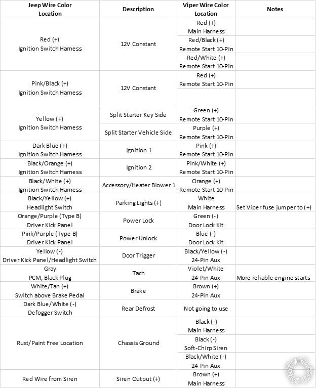
A few thoughts on this. First and foremost is safety. Without a Hood Pin input, the Viper could remote start the engine with the hood up and engine repair underway or during an oil change, etc. Most install guides say it's Mandatory but the R/S function will work without it. The next is the 5806V alarm monitoring. Without a Hood Pin input the Viper alarm won't be triggered if the hood is opened. No big deal you say because the vehicle has an inside hood release. Again, it's your choice, one less wire to run... As for the extra hole and rust, there are options there. In a non-alarm R/S install, I use a mercury tilt switch mounted to a hood hinge bolt. No rust and better reliability. Photo below :
3) Green/Black (-) 200mA Factory Alarm Disarm Output - OEM Alarm Disarm: VIOLET / YELLOW (-) DRIVER'S KICK PANEL does your Jeep have the factory alarm?
- I do not believe my Jeep has the factory alarm. I don't know exactly where to look for it at, and I've tried setting it off, by using the key fob to lock the door and then manually flipping the lock from inside the door and opening the door. This seems to set off the alarm on other vehicles. Not sure how to test with this vehicle.
You probably don't have the Factory Alarm system. Just having a Panic button on the factory FOB is not indicative of a Factory Alarm system. The test you mention is close. Try this, while sitting in the running vehicle, turn off the engine and remove the key. Stay seated but open the drivers door and press the lock button on the door panel twice, then close the door. Watch the dash / instrument cluster for a flashing light. If there is one, see if it slows down after 30 seconds or so. Wait about 2 minutes, then open the drivers door using the inside handle ( not the factory FOB ). If the horn starts beeping, you have the alarm system. No beeps, no alarm and no need for this wire connection.
5) Green (+) Starter Input (KEY SIDE of the failsafe starter disable) - cut YELLOW (+) IGNITION SWITCH HARNESS - key side
Violet (+) Starter Output (CAR SIDE of the failsafe starter disable) - cut YELLOW (+) IGNITION SWITCH HARNESS - vehicle side
- What do you mean by cut YELLOW (+) ??
One of the nice things about a Viper Alarm system is the Starter Kill and Anti-Grind feature. If the Viper system is locked and the alarm is on, if the car was broken into and a duplicate key was used to start the engine, the Starter Kill feature would prevent cranking. With the Anti-Grind feature, it will prevent engaging the starter during key-take-over. To achieve these features, the vehicles Starter wire is cut and the Vipers two Starter wires and spliced into the circuit. Everything works as normal with a key start but the Viper adds these extra features. If you did not want to cut the vehicles Starter wire, just omit the Vipers Green wire and only connect the Vipers Violet wire to the vehicles uncut Starter wire.
6) White Parking Light Output - #30 Common of onboard relay - Parking Lights: BLACK / YELLOW AT HEADLIGHT SWITCH. Set Viper fuse jumper to (+)
- What do you mean by "Set Viper fuse jumper to (+)"?
The Viper has the ability to output either a (+) or a (-) Parking Light output on the White wire. This is determined by an internal 10 Amp fuse that is used as a jumper setting. On the top side on the Viper controller is a small sliding access cover. The fuse is beneath that cover.
-------------
Soldering is fun!
- Is this required? It notates on the Viper Remote Start that it is required for Manual Transmission Vehicles. Mine is automatic. What benefits would I gain from this?
You are correct in that Tach Mode is required for a Manual Transmission install. While it's mandatory for a MT install, it can still be used for any install. Virtual Tach is the Default. However, most installers will run in Tach Mode because it provides more reliable engine starts, especially in cold environments. So it's your choice, one less wire or more reliable operation.
2) Gray (-) Hood Pin Input (N/C or N/O) - connect to kit supplied hood pin switch you installed
- Is this required? I really didn't want to go through the hassle of drilling into the frame of the Jeep under the hood somewhere to install a hood pin kit. I was planning to forego this unless there's a reason it is required or if there is some amazing benefit to it.
A few thoughts on this. First and foremost is safety. Without a Hood Pin input, the Viper could remote start the engine with the hood up and engine repair underway or during an oil change, etc. Most install guides say it's Mandatory but the R/S function will work without it. The next is the 5806V alarm monitoring. Without a Hood Pin input the Viper alarm won't be triggered if the hood is opened. No big deal you say because the vehicle has an inside hood release. Again, it's your choice, one less wire to run... As for the extra hole and rust, there are options there. In a non-alarm R/S install, I use a mercury tilt switch mounted to a hood hinge bolt. No rust and better reliability. Photo below :
3) Green/Black (-) 200mA Factory Alarm Disarm Output - OEM Alarm Disarm: VIOLET / YELLOW (-) DRIVER'S KICK PANEL does your Jeep have the factory alarm?
- I do not believe my Jeep has the factory alarm. I don't know exactly where to look for it at, and I've tried setting it off, by using the key fob to lock the door and then manually flipping the lock from inside the door and opening the door. This seems to set off the alarm on other vehicles. Not sure how to test with this vehicle.
You probably don't have the Factory Alarm system. Just having a Panic button on the factory FOB is not indicative of a Factory Alarm system. The test you mention is close. Try this, while sitting in the running vehicle, turn off the engine and remove the key. Stay seated but open the drivers door and press the lock button on the door panel twice, then close the door. Watch the dash / instrument cluster for a flashing light. If there is one, see if it slows down after 30 seconds or so. Wait about 2 minutes, then open the drivers door using the inside handle ( not the factory FOB ). If the horn starts beeping, you have the alarm system. No beeps, no alarm and no need for this wire connection.
5) Green (+) Starter Input (KEY SIDE of the failsafe starter disable) - cut YELLOW (+) IGNITION SWITCH HARNESS - key side
Violet (+) Starter Output (CAR SIDE of the failsafe starter disable) - cut YELLOW (+) IGNITION SWITCH HARNESS - vehicle side
- What do you mean by cut YELLOW (+) ??
One of the nice things about a Viper Alarm system is the Starter Kill and Anti-Grind feature. If the Viper system is locked and the alarm is on, if the car was broken into and a duplicate key was used to start the engine, the Starter Kill feature would prevent cranking. With the Anti-Grind feature, it will prevent engaging the starter during key-take-over. To achieve these features, the vehicles Starter wire is cut and the Vipers two Starter wires and spliced into the circuit. Everything works as normal with a key start but the Viper adds these extra features. If you did not want to cut the vehicles Starter wire, just omit the Vipers Green wire and only connect the Vipers Violet wire to the vehicles uncut Starter wire.
6) White Parking Light Output - #30 Common of onboard relay - Parking Lights: BLACK / YELLOW AT HEADLIGHT SWITCH. Set Viper fuse jumper to (+)
- What do you mean by "Set Viper fuse jumper to (+)"?
The Viper has the ability to output either a (+) or a (-) Parking Light output on the White wire. This is determined by an internal 10 Amp fuse that is used as a jumper setting. On the top side on the Viper controller is a small sliding access cover. The fuse is beneath that cover.
-------------
Soldering is fun!
Posted By: firefighter1466
Date Posted: January 31, 2021 at 9:45 PM
So in response to:
One of the nice things about a Viper Alarm system is the Starter Kill and Anti-Grind feature. If the Viper system is locked and the alarm is on, if the car was broken into and a duplicate key was used to start the engine, the Starter Kill feature would prevent cranking. With the Anti-Grind feature, it will prevent engaging the starter during key-take-over. To achieve these features, the vehicles Starter wire is cut and the Vipers two Starter wires and spliced into the circuit. Everything works as normal with a key start but the Viper adds these extra features. If you did not want to cut the vehicles Starter wire, just omit the Vipers Green wire and only connect the Vipers Violet wire to the vehicles uncut Starter wire.
- If I want to use this feature, how would I do that? I'm assuming based on your notes above I would cut the yellow wire in the middle, and on the side leading to the key I would connect the green wire and on the side towards the vehicle I would connect the purple wire?
The Viper has the ability to output either a (+) or a (-) Parking Light output on the White wire. This is determined by an internal 10 Amp fuse that is used as a jumper setting. On the top side on the Viper controller is a small sliding access cover. The fuse is beneath that cover.
- I just opened that sliding access, which surprisingly was not very easy to slide, haha. Looks as though the fuse wasn't on there at all it was in a "hold" area to the side. I removed it and placed it on the + and center.
If all of this stands as noted, would you mind looking this over to make sure I'm not missing anything? There may be more questions to come, but I feel this may be enough to make me confident enough to start tapping into wires. I've got the dash pulled all the way apart so everything is accessible.
-------------
Jon
Posted By: kreg357
Date Posted: January 31, 2021 at 10:21 PM
Re Parking Light jumper/fuse - usually they are just bouncing around after rough shipping.
Re Starter Kill - yep, just cut the vehicles starter wire in an easily accessible place and make the Viper wire connections. It's best to solder and use heat shrink tube for long term reliability.
Please consider using a Hood Pin. It is possible to make a bracket/support out of a piece of stainless steel secured on existing fender mounting bolts that would hold the hood pin and not add any holes to the vehicle. If the mercury or ball bearing tilt switch is acceptable, search EBay on AU46 or Directed 8613 or 8613. It's an important safety feature.
You will have to do a Tach Learn procedure if going in Tach Mode to learn the tach signal.
The wire chart looks correct. You can join the Viper Chassis Ground wire with the Neutral Safety wire at the Viper and just run the one Black wire to the vehicles frame ground.
-------------
Soldering is fun!
Posted By: firefighter1466
Date Posted: January 31, 2021 at 10:29 PM
Re Starter Kill - I do not know how to solder, I've got heat shrink and crimps. I've also got some posi connectors like you'd use for audio wiring (next project), that I can steal and use for this if you feel that would hold up better. Both wires go in and it screws them together and holds them.
Re Hood Pin - I do not mind using the hood pin - can you explain in more detail how and where it needs to be mounted. I'm just not sure how to get it setup correctly, and don't want to drill multiple holes. In addition, how do I get the wire from inside the vehicle to under the hood without additional drilling. Everything looks pretty well sealed and wrapped under my column.
Re Tach Learn - I don't guess I have a choice if I want reliable engine starts like you mentioned.. How would I go about this procedure? Would this be after everything else is wired up and completed?
Re Wire Chart - Noted on the wires.
-------------
Jon
Posted By: kreg357
Date Posted: February 01, 2021 at 8:35 AM
Re Starter Kill - I do not know how to solder, I've got heat shrink and crimps. I've also got some posi connectors like you'd use for audio wiring (next project), that I can steal and use for this if you feel that would hold up better. Both wires go in and it screws them together and holds them.
Sorry, can't help much here. I always solder everything. I really haven't used or tested any other methods. As a side note, during a recent install on a RAM 2500, I had to repair a butt crimp connector in the door sill harness from a stereo upgrade because I moved it slightly to gain access to a door pin wire and it just separated. Here is a link to a video from Bulldog security showing R/S install instructions. In the video, starting at 4:44 and going through 6:50, it details how to make wire connections without soldering. https://www.bulldogsecurity.com/bdnew/remoteStartervideo500.html I would suggest using a high quality electrical tape like Scotch Super 33+. I have found that other brands will dry out and unravel in a few years, causing big problems.
Re Hood Pin - I do not mind using the hood pin - can you explain in more detail how and where it needs to be mounted. I'm just not sure how to get it setup correctly, and don't want to drill multiple holes. In addition, how do I get the wire from inside the vehicle to under the hood without additional drilling. Everything looks pretty well sealed and wrapped under my column.
With a tilt hood pin, I check for clearance when closed on the vehicles driver side hood hinge. There are usually two bolts securing the hood to the hinge. I remove one bolt and reinstall it with the tilt switch. The switch can be bent down to adjust when it actuates and kills the R/S'ed engine. No holes to drill, no extra fasteners to buy and they don't rust and seize up like regular hood pins. The only down side is that for proper operation, they must be adjust so the the hood is opened half way to trigger which isn't ideal for alarm systems. Here is another photo of this :
The hood pin that came in the kit is spring loaded and triggers when fully extended. If your vehicle had a corner where there were bolts holding a fender on one side and another on the radiator side, you could use those two bolt to secure a piece of stainless steel between and mount the hood pin through that. The only issue would be the hood contact area and pin adjustment.
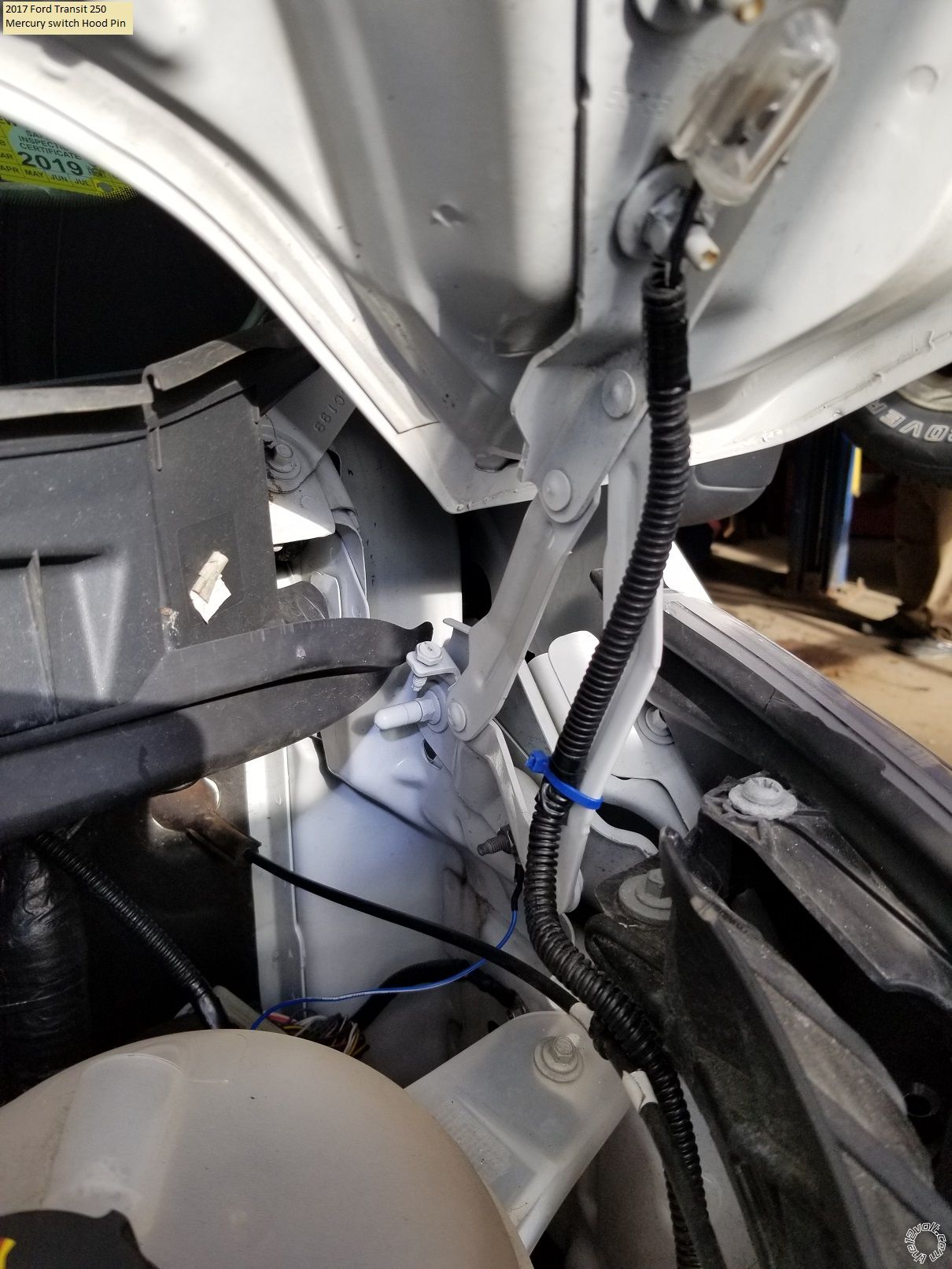
Getting a wire through the firewall can be difficult on some cars. Some cars have an unused grommet in the firewall and the wire(s) can be pushed through them. Some cars have a big grommet with a large wire harness. If there is some space on the side of the wire harness and the hole, you can use a coat hanger to punch through the rubber grommet material and pass your wire(s) through. Just be careful that you don't damage any wires on the other side. Even the grommet that is used to pass the hood release cable through the firewall is acceptable. Use a flashlight and check the drivers side firewall from the engine side for any possible grommet locations, then find them on the inside. Every car is different. Your system has a siren that should be mounted in the engine compartment and the Brown wire ( along with the Hood Pin wire ) needs to be run.
Re Tach Learn - I don't guess I have a choice if I want reliable engine starts like you mentioned.. How would I go about this procedure? Would this be after everything else is wired up and completed?
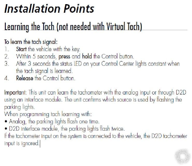
The brief install guide included with the 5806V has the Tach Learn process listed. Here it is in case you can't find it :
-------------
Soldering is fun!
Sorry, can't help much here. I always solder everything. I really haven't used or tested any other methods. As a side note, during a recent install on a RAM 2500, I had to repair a butt crimp connector in the door sill harness from a stereo upgrade because I moved it slightly to gain access to a door pin wire and it just separated. Here is a link to a video from Bulldog security showing R/S install instructions. In the video, starting at 4:44 and going through 6:50, it details how to make wire connections without soldering. https://www.bulldogsecurity.com/bdnew/remoteStartervideo500.html I would suggest using a high quality electrical tape like Scotch Super 33+. I have found that other brands will dry out and unravel in a few years, causing big problems.
Re Hood Pin - I do not mind using the hood pin - can you explain in more detail how and where it needs to be mounted. I'm just not sure how to get it setup correctly, and don't want to drill multiple holes. In addition, how do I get the wire from inside the vehicle to under the hood without additional drilling. Everything looks pretty well sealed and wrapped under my column.
With a tilt hood pin, I check for clearance when closed on the vehicles driver side hood hinge. There are usually two bolts securing the hood to the hinge. I remove one bolt and reinstall it with the tilt switch. The switch can be bent down to adjust when it actuates and kills the R/S'ed engine. No holes to drill, no extra fasteners to buy and they don't rust and seize up like regular hood pins. The only down side is that for proper operation, they must be adjust so the the hood is opened half way to trigger which isn't ideal for alarm systems. Here is another photo of this :
The hood pin that came in the kit is spring loaded and triggers when fully extended. If your vehicle had a corner where there were bolts holding a fender on one side and another on the radiator side, you could use those two bolt to secure a piece of stainless steel between and mount the hood pin through that. The only issue would be the hood contact area and pin adjustment.
Getting a wire through the firewall can be difficult on some cars. Some cars have an unused grommet in the firewall and the wire(s) can be pushed through them. Some cars have a big grommet with a large wire harness. If there is some space on the side of the wire harness and the hole, you can use a coat hanger to punch through the rubber grommet material and pass your wire(s) through. Just be careful that you don't damage any wires on the other side. Even the grommet that is used to pass the hood release cable through the firewall is acceptable. Use a flashlight and check the drivers side firewall from the engine side for any possible grommet locations, then find them on the inside. Every car is different. Your system has a siren that should be mounted in the engine compartment and the Brown wire ( along with the Hood Pin wire ) needs to be run.
Re Tach Learn - I don't guess I have a choice if I want reliable engine starts like you mentioned.. How would I go about this procedure? Would this be after everything else is wired up and completed?
The brief install guide included with the 5806V has the Tach Learn process listed. Here it is in case you can't find it :
-------------
Soldering is fun!
Posted By: firefighter1466
Date Posted: February 01, 2021 at 2:10 PM
Gotcha - got a question in reference to my above chart.
There's 2 12v Constants in this harness? I'm to wire that one thing definitely to the pink/black and the others to the red?
How should I go about wiring multiple things from the remote start to the same thing on the harness in the vehicle? Can they be wired together then to the vehicle or do they need to be spliced into different areas of the harness?
-------------
Jon
Posted By: kreg357
Date Posted: February 01, 2021 at 2:29 PM
I would split it up 2 and 2 to each +12V constant vehicle wire. Balance the load better. So Red/Black and Red/White to Red. Red and Red to Pink/Black. They are all fused so strip about 1" of insulation from the vehicle wire and make the two connections. I might be tempted to combine the thin Red into the thick Red near the end of the wire run and just make one connection with the end of the thick Red.
Did the Bulldog video help?
-------------
Soldering is fun!
Did the Bulldog video help?
-------------
Soldering is fun!
Posted By: firefighter1466
Date Posted: February 01, 2021 at 4:17 PM
It did I'm currently using that method now to wire everything up.
Quick question - what should I do for wires that are not being used at all? Should they be taped up? Cut off?
-------------
Jon
Quick question - what should I do for wires that are not being used at all? Should they be taped up? Cut off?
-------------
Jon
Posted By: kreg357
Date Posted: February 01, 2021 at 4:26 PM
I usually cut them to about 2" and then bundle them together using heat shrink tube to insulate the cut ends.
-------------
Soldering is fun!
-------------
Soldering is fun!
Posted By: firefighter1466
Date Posted: February 01, 2021 at 10:03 PM
Hoping you're still awake trying to finish this thing up tonight. Do you suppose this is the right yellow wire in the "Driver Kick Panel/Headlight Switch" for the Door Trigger? It's a thick wire, the yellow wire in the headlight switch is pretty thin. The harness I'm hooking up is pretty thin, but then again it looks like I've had to mix and match heavier gauge wires with thinner wires throughout this process some anyway.
-------------
Jon
-------------
Jon
Posted By: firefighter1466
Date Posted: February 01, 2021 at 10:13 PM
Also for the White/Tan above the brake, there are 2 going into the same slot in the harness connector. Do I need to tie into both of them, or just one will suffice? I would think one since they're going in together.
-------------
Jon
-------------
Jon
Posted By: kreg357
Date Posted: February 02, 2021 at 2:44 AM
firefighter1466 wrote:If they are combined at the connector, you can use either one. This is only an input wire for the Viper and doesn't draw any current.
Also for the White/Tan above the brake, there are 2 going into the same slot in the harness connector. Do I need to tie into both of them, or just one will suffice? I would think one since they're going in together.
-------------
Soldering is fun!
Posted By: kreg357
Date Posted: February 02, 2021 at 2:54 AM
On the Yellow (-) Door Pin wire, the thick wire in the DKP doesn't look right. One wire listing indicates it will be in a Gray 2 Pin connector. It is easy enough to test it using the DMM as described previously. The correct wire will show +12V when the door is open.
-------------
Soldering is fun!
-------------
Soldering is fun!
Posted By: firefighter1466
Date Posted: February 02, 2021 at 8:05 AM
Should most wires be similarly sized or will there be a few that may be smaller/larger than each other?
-------------
Jon
-------------
Jon
Posted By: kreg357
Date Posted: February 02, 2021 at 8:30 AM
On your older Jeep, I would think most will be nearly the same size. The Parking Light wire might be slightly different gauge. Obviously, any big differences should be re-checked/verified with the DMM. Some newer cars do have major differences in the ignition wires.
-------------
Soldering is fun!
-------------
Soldering is fun!
Posted By: firefighter1466
Date Posted: February 02, 2021 at 8:43 AM
The parking light was slightly larger. It was a much smaller wire inside of the headlight switch and the white wire from my kit was right much larger. The only other one that I can think of right off hand is the brown wire that goes through the firewall to the siren. They designed these to go together, but the red wire is super small compared to that brown wire. I think most everything else has matched up one for one. Got a few more to go and I'll be able to test everything before mounting the box.
I would imagine once I get everything wired, I can reconnect the battery, close the hood (hood pin switch), connect the harnesses to the box and then connect the control center piece to it and do the program? I would imagine I should be able to fire it up like normal before even doing that to make sure that everything is connected correctly for the ignition portion. I feel most confident in the ignition wires and others because they stood out more than all of the other column wires as they were thicker gauge wire and matched up with the harnesses.
-------------
Jon
Posted By: kreg357
Date Posted: February 02, 2021 at 10:02 AM
Sequence sounds good. I usually do the install hot and just leave the fuses out of the R/S unit. Once everything is connected, you can test with a Lock and Unlock. The door locks should work and the Parking Lights should flash. You can also test the Viper alarm function and siren. The remote start function is in-op due to the Viper being in Manual Transmission Mode. Next would be Viper programming. Set to Auto Trans and Tach Mode. Then start the engine with the key and allow to warm up. Turn it off and the do the Tach Learn. If successful, turn off the vehicle and try a remote start. Test the Brake shutdown and the hood pin shutdown.
-------------
Soldering is fun!
-------------
Soldering is fun!
Posted By: firefighter1466
Date Posted: February 02, 2021 at 4:25 PM
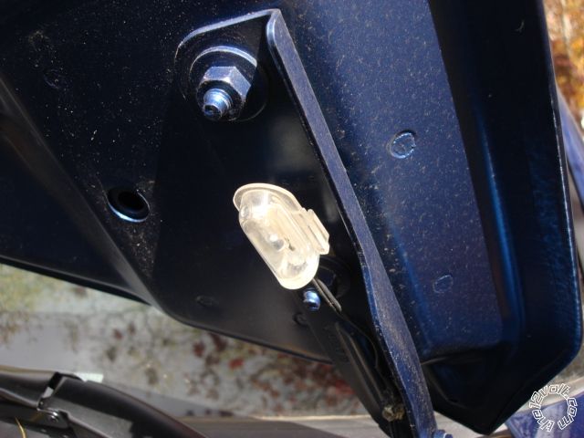
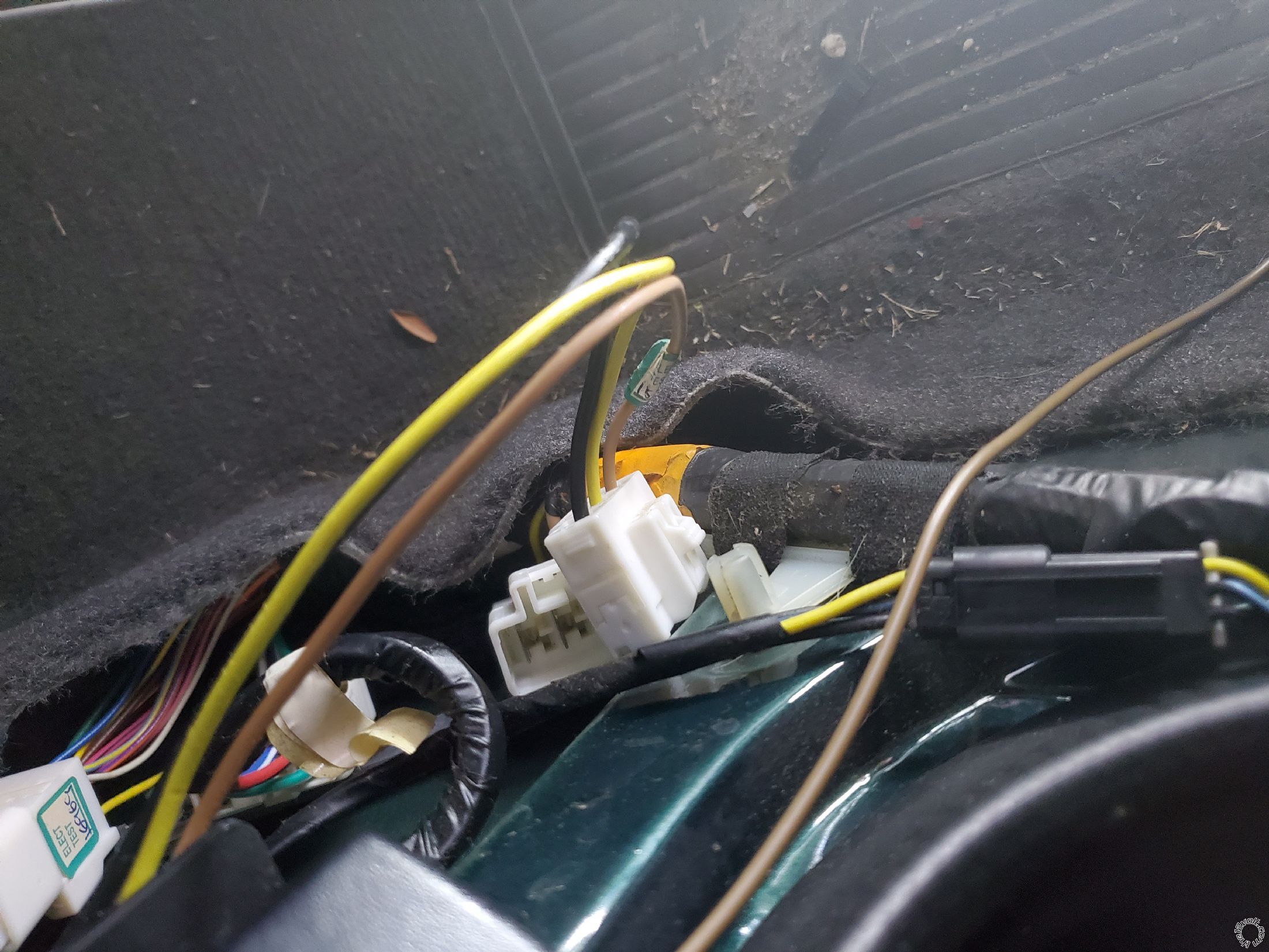
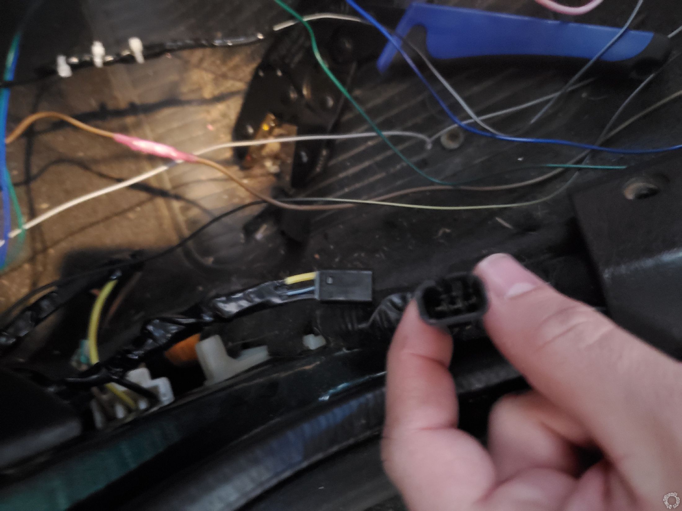
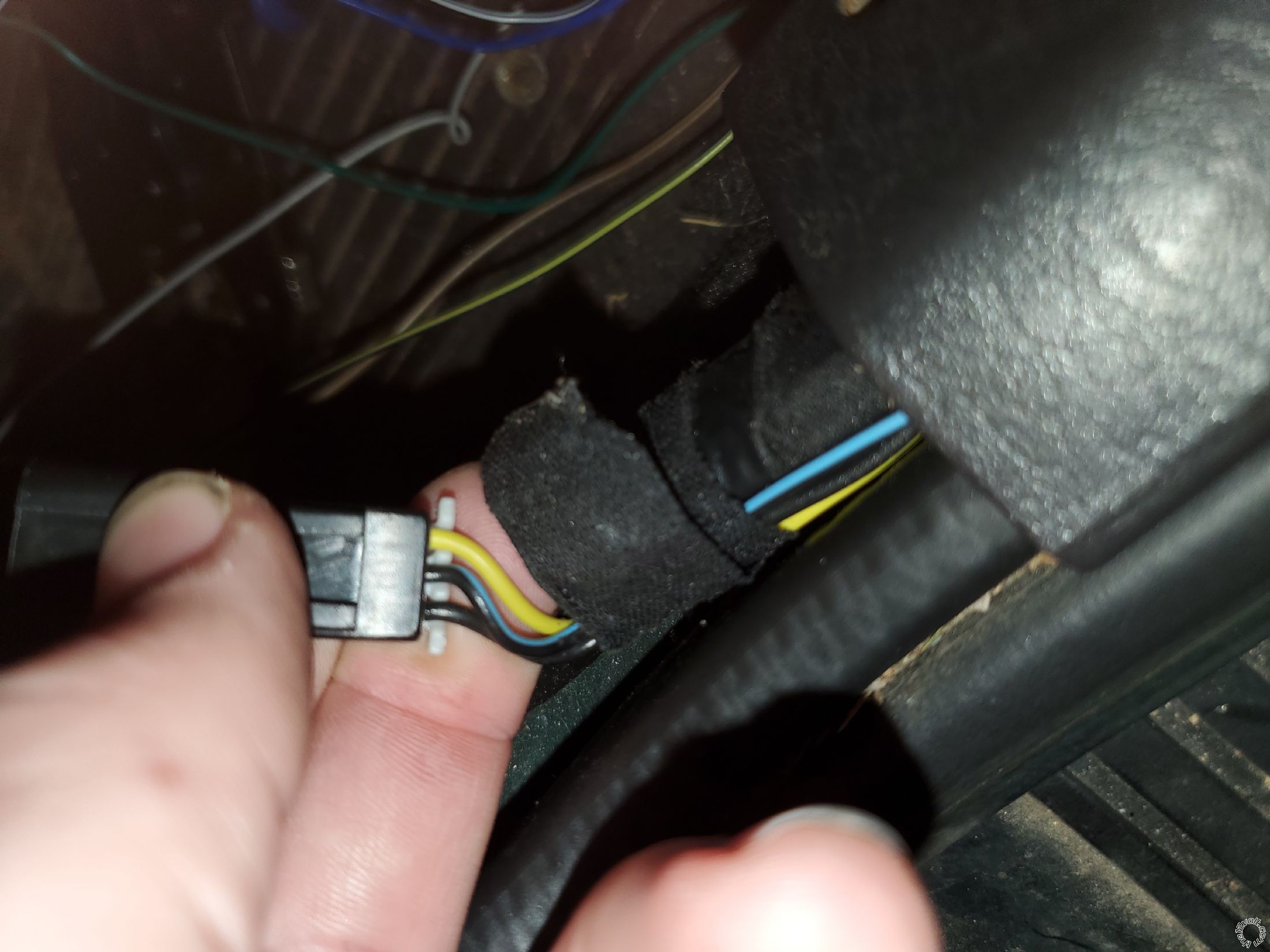
Re the yellow door wire. I didn't find a gray 3 pin connector, but I found a 2 pin connector behind the kick plate that runs along the floor next to the side trim at the bottom. When the park lights are on and the door is open the door makes a dinging sound. When I disconnect this plug the sound goes off. When I close the door this sound goes off. Would this be the correct yellow wire? I have attached an image. I don't have an exposed 12v constant to tap into in order to test unless you have a better alternative for testing.
-------------
Jon
-------------
Jon
Posted By: firefighter1466
Date Posted: February 02, 2021 at 5:02 PM
Also - RE: Next would be Viper programming. Set to Auto Trans and Tach Mode. Then start the engine with the key and allow to warm up. Turn it off and the do the Tach Learn. If successful, turn off the vehicle and try a remote start. Test the Brake shutdown and the hood pin shutdown.
How would I do this part? As far as set to Auto Trans and Tach Mode?
-------------
Jon
How would I do this part? As far as set to Auto Trans and Tach Mode?
-------------
Jon
Posted By: kreg357
Date Posted: February 02, 2021 at 5:17 PM
Re Yellow Door Pin wire - yes that looks like it. My info posted above said Gray 2 Pin plug. Again, the correct way to do this is with a test using a DMM.
Re Viper Programming : Page 2 of the 2 page install guide included with the Viper system has the program change procedure using the supplied remotes. Menu 3, Item 1 and Item 2 are the two options that need to be changed. You will need the Door Pin functional to enter in to Programming Mode.
-------------
Soldering is fun!
Posted By: firefighter1466
Date Posted: February 02, 2021 at 5:50 PM
I understand that would be the best way to do it but what do you recommend as an alternate or easier way to check when i dont have an exposed 12V constant?
-------------
Jon
-------------
Jon
Posted By: kreg357
Date Posted: February 02, 2021 at 6:47 PM
You could get +12V from the (+) battery post via a long piece of excess, unused Viper wire, or by pushing the Red DMM test lead into the Viper connector where the +12V power comes in. Might be other convenient places. If you just want to get the Viper into Programming Mode, you could just touch the Viper (-) Door Pin Input wire to Chassis Ground.
The (-) Door Trigger Input is an input to the Viper. As such it is only a high impedance wire that monitors another for a signal. The Yellow wire is the correct color and location from the wire guide. Also you are able to effect the door open chime by interrupting the signal. I would think it might be OK to connect the Viper Door Trigger Input wire and then see if the Viper alarm will trigger when the Viper Alarm is set and the door is opened. I'm assuming that the Viper is able to control the locks, the siren and Parking Lights.
-------------
Soldering is fun!
Posted By: firefighter1466
Date Posted: February 02, 2021 at 9:55 PM
Thanks - the only wires I have left are to ground the 2 black wires inside and
"Gray
PCM, Black Plug" Tach "Violet/White
24-Pin Aux" More reliable engine starts
Where do I find this wire? I can't seem to find anything online.
-------------
Jon
"Gray
PCM, Black Plug" Tach "Violet/White
24-Pin Aux" More reliable engine starts
Where do I find this wire? I can't seem to find anything online.
-------------
Jon
Posted By: firefighter1466
Date Posted: February 02, 2021 at 11:39 PM
So I skipped tach mode for now because it looked like it wanted me to tap into the huge spool of harness in the front and I'm just not willing to do that right now since I'm inexperienced. I read that while virtual tach isn't the most ideal, it does work fine.
Here's my issue. Alarm works great. Unlock & Lock work great. I enabled "garage mode" and disabled it as well. However, when I'm trying to remote start it "clicks" 7 times at the box. The lights don't flash, but I'm assuming that's because I've got the dash partially taken apart and the headlights have a control button that kind of stabs in and pulls in and out. The seven clicks I'm assuming are like the 9 clicks that were slow for garage mode when turning off and fast when turning on. So 7 clicks means it is in manual transmission mode. I tried going into the programming, which the instructions say:
Open a door
Turn the key to ON then OFF
Press and hold the control center button until 3 chirps representing 3rd menu.
That's where I get stuck - I never get any chirps when holding that button. I could hold it for 20 minutes and it wouldn't do a thing.
Any thoughts???
-------------
Jon
Posted By: kreg357
Date Posted: February 03, 2021 at 3:01 AM
Yes, 7 blinks is MT Mode.
Does the Viper alarm/siren go off when you open a door? This would verify that you are connected to a good Door Pin Trigger source.
Do you have the Vipers thick Pink ING1 wire connected to the Jeeps Ignition wire. You can test for +12V at the Pink wire at the Viper controller plug when you rotate the ignition key to ON position using the DMM.
You can usually get a good Tach signal at any Fuel Injector. It's a two pin plug. Check several F.I.s and use the non-common colored wire at any F I.
-------------
Soldering is fun!
Posted By: firefighter1466
Date Posted: February 03, 2021 at 10:21 AM
So.. I locked the doors with the viper remote. Flipped the lock manually from the inside of the Jeep and opened the door. The alarm did not go off, but the lights came on like they usually would inside noting that the door is open. No alarm though. Once I put the key in and turned it, the alarm started going off.
Am I doing something wrong for testing the door? Should I try opening it from the inside without flipping the lock manually? The remote didn't react to it being flipped, I would think that would trigger the alarm like it would normally on a vehicle just being opened regardless of how it was unlocked manually.
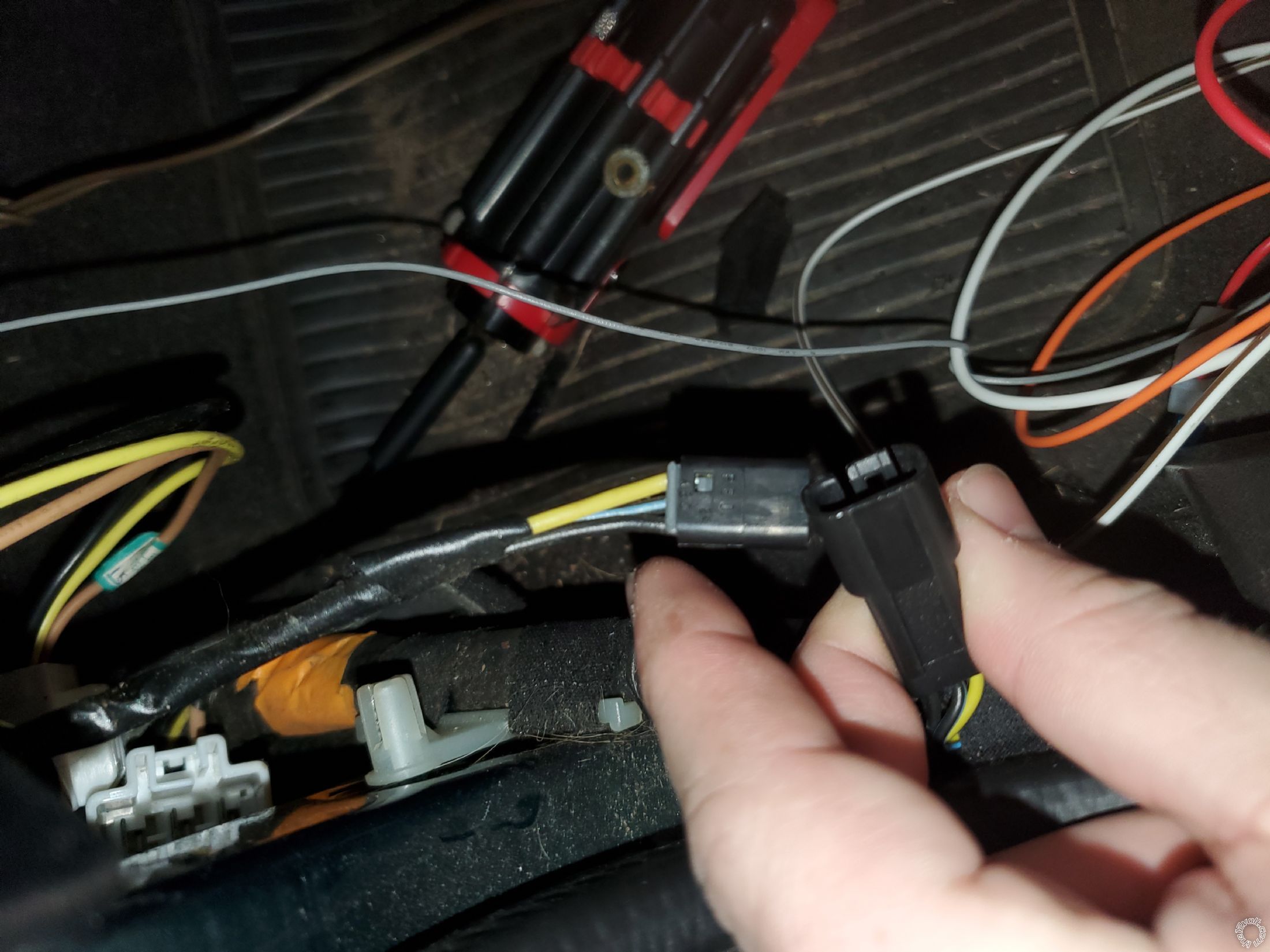
If this is the case, I apparently don't have the correct wire. Could it be a different wire than the yellow wire in that small 3-pin? I noticed that when I had the key in the ignition and opened the door that it would ding until I disconnected that plug. That leads me to believe that the door trigger is in that switch, however, I'm not sure.
There are 3 wires in that pin. Black, Black/Blue, Yellow. When I touch the DMM to the Black and Black/Gray I get like 12V whether the door is open or not. When I touch it to black and yellow it's like 7V.
I'm totally confused on what is going on here. Am I on the wrong yellow wire? See attached images.
Thanks,
-------------
Jon
Am I doing something wrong for testing the door? Should I try opening it from the inside without flipping the lock manually? The remote didn't react to it being flipped, I would think that would trigger the alarm like it would normally on a vehicle just being opened regardless of how it was unlocked manually.
If this is the case, I apparently don't have the correct wire. Could it be a different wire than the yellow wire in that small 3-pin? I noticed that when I had the key in the ignition and opened the door that it would ding until I disconnected that plug. That leads me to believe that the door trigger is in that switch, however, I'm not sure.
There are 3 wires in that pin. Black, Black/Blue, Yellow. When I touch the DMM to the Black and Black/Gray I get like 12V whether the door is open or not. When I touch it to black and yellow it's like 7V.
I'm totally confused on what is going on here. Am I on the wrong yellow wire? See attached images.
Thanks,
-------------
Jon
Posted By: firefighter1466
Date Posted: February 03, 2021 at 10:40 AM
In addition, looking at the 2000 Jeep manual on this website, it shows that the "Door Trigger" is located "Yellow (-) Under Dash Light or Overhead Module".
I watched a video on Youtube of someone disassembling an overhead module and the yellow wire I saw in there was right much bigger of a wire (smaller gauge) than the one I tapped into already. Could this potentially be right? How would this harness travel to the overhead module and where would be the best place to tap into it?
Thanks,
-------------
Jon
Posted By: kreg357
Date Posted: February 03, 2021 at 10:51 AM
The info I found was a Gray two pin connector with the Yellow Door Pin wire. You really have to test it with a DMM to be sure you have the correct wire.
If the Viper was locked and the alarm armed, the Viper siren should have gone off when the door was opened. The Viper also watches the Ignition input and if it goes to +12V while armed, it will set off the siren.
Here is some info on the Yellow wire :
All Door Trigger / Dome Light YELLOW (-) AT ANY PIN SWITCH OR HEADLIGHT SWITCH
Left Front Door Trigger Yellow (-) @ drivers kick in a gray 2 pin connector
Are there door pin switches in the door jams? With only one door open, when you press the switch does the dome light go out? Might be a delayed fade out. Can the pin switch be be removed? Just pull it out a little and check the wire color and then find that wire in the door sill harness. Then test. Can you remove door pillar trim and look behind the door pin? Same routine.
The Headlight switch might be the easiest location to locate the wire. How many Yellow wires there? Again, test with a DMM to be sure.
-------------
Soldering is fun!
Posted By: firefighter1466
Date Posted: February 03, 2021 at 11:31 AM
Again - I've struggled to find an accurate way to test with the DMM. I just disconnected it from where it was connected and tied it into the headlight solid yellow wire. Still nothing. No command center, no remote start, no alarm with door opening. I pushed on the pin in the door and the lights go off. I looked inside the Jeep the best I could and there's only one set of wires going in the hole right there of the frame and it looks like the same 3 wire harness that I tapped into, on the same side. Yellow, Black & Black/Blue.
I'm stumped. There has to be something off.
-------------
Jon
I'm stumped. There has to be something off.
-------------
Jon
Posted By: kreg357
Date Posted: February 03, 2021 at 11:52 AM
Might have figured it out. On Page 1 you show the Vipers Green (-) Door Input wire going to the Jeeps Yellow Door Trigger wire and I confirmed this. Then on Page 2 in your chart, you show the Viper Black/Yellow Dome Light Output as the only wire going to the Yellow wire. You need the Vipers Green (-) Door Input wire connected to the Yellow wire. Exactly which Viper wire is going to the Yellow wire?
-------------
Soldering is fun!
-------------
Soldering is fun!
Posted By: firefighter1466
Date Posted: February 03, 2021 at 11:55 AM
So I found the plug going into the passenger kick panel that controls the lights when the door push pins are pushed in and door is opened. I pulled that plug out and put a constant on the battery and the black in the yellow pin of the plug but it stayed at 12v whether the door was opened or closed. Should I not have tested it at that module? Should I have tested it past that at some point? I'm trying to figure this out but even using a DMM isn't making sense for making out where I need to be connected.
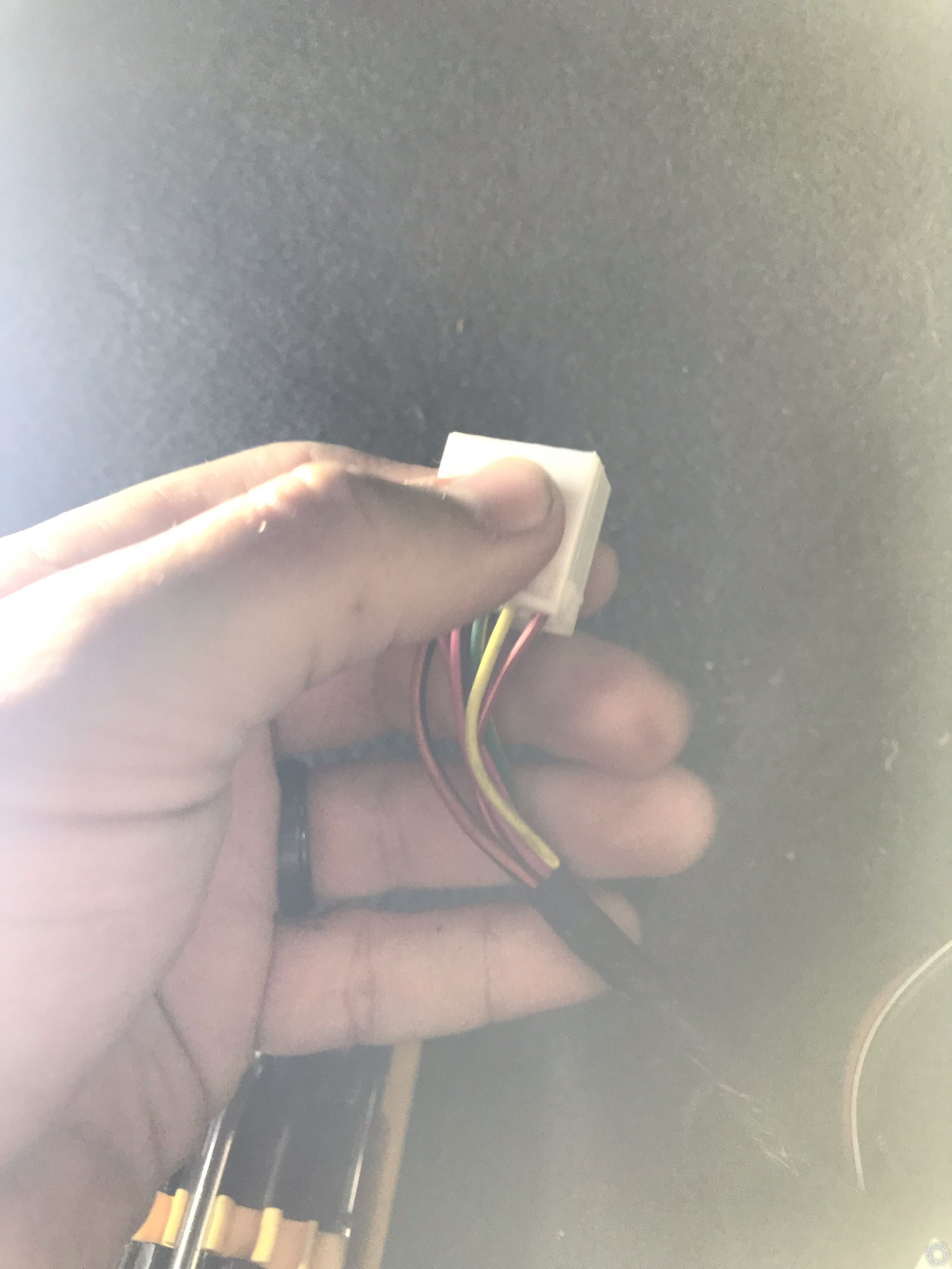
-------------
Jon
-------------
Jon
Posted By: firefighter1466
Date Posted: February 03, 2021 at 11:57 AM
kreg357 wrote:My image on Page 2 or 3 that shows my chart is exactly how I've got it wired up. I think that was the dome light output wire instead of the door input wire? Did we mix those up?
Might have figured it out. On Page 1 you show the Vipers Green (-) Door Input wire going to the Jeeps Yellow Door Trigger wire and I confirmed this. Then on Page 2 in your chart, you show the Viper Black/Yellow Dome Light Output as the only wire going to the Yellow wire. You need the Vipers Green (-) Door Input wire connected to the Yellow wire. Exactly which Viper wire is going to the Yellow wire?
-------------
Jon
Posted By: kreg357
Date Posted: February 03, 2021 at 12:51 PM
They are two different things. What we need right now is the Viper Green (-) Door Trigger Input getting a valid door pin signal. This is for the Viper Alarm and to get into Viper Programming Mode. The Viper Dome Light wire is an output that the Viper uses to turn on the vehicles dome light after an unlock.
-------------
Soldering is fun!
-------------
Soldering is fun!
Posted By: firefighter1466
Date Posted: February 03, 2021 at 1:51 PM
So where should the dome light viper wire be moved to?
-------------
Jon
-------------
Jon
Posted By: kreg357
Date Posted: February 03, 2021 at 2:46 PM
Well, I guess we should set some priorities. Dome Light Supervision is pretty far down the list if the Viper Alarm isn't working, the remote start isn't working and you can't get into Programming Mode. As you remember from reading the Install Guide, here is the description of the Dome Light Output :
This (-) 200mA output is used to drive the dome light circuit in the vehicle. This output activates when disarming/unlocking the system and when turning the ignition OFF in the vehicle (ignition controlled Dome Light is programmable ON/OFF). (see Ign-controlled Dome Light in Feature Menus for more detail).
It is possible that you do not need this connection and even if you need this connection you may not really want it. First a test. With the Dome Light Output not connected, try a Viper Unlock command. Do the interior / dome lights come on? If yes, you don't need this connection. If no, do you want the interior light to come on with a Viper Unlock? Either way, this wire not connected is not a show stopper. For right now we can live without it. The more important thing is to get everything else working.
So, did connecting the Viper Green (-) Door Trigger Input wire to the Yellow wire get the Viper Alarm to trigger when a door is opened while armed? If , yes, came you now get into Viper Programming Mode to make the necessary changes to get the R/S function working?
If you are still having trouble locating the Yellow Door Pin wire lets try this.
Set the DMM to 20 Volts DC. Go to the battery and hold the Red test lead on the Battery Positive terminal and the Black test lead on the negative terminal. The DMM should show around +12 Volts DC.
Next, under the dash, push the DMM Red test lead into the plastic connector at the thick Red +12V input wire such that the test lead makes good contact with the plug pin. Touch the Black Test lead to a chassis ground point. The DMM should show the same ~ +12V as the battery posts test.
Finally, move the Black test lead to the suspect Yellow wire. With all the doors closed, you should see 0V at the DMM. Open the drivers door. The DMM should now read ~ +12V.
It's possible the Viper's (-) Door Trigger Input is damaged / bad. Very rare, but possible. Try getting into Viper Programming Mode by briefly touching the Viper Green Door Trigger Input wire to Chassis Ground to start the process of going into Programming Mode. Can you get into Programming Mode this way?
-------------
Soldering is fun!
Posted By: firefighter1466
Date Posted: February 03, 2021 at 2:49 PM
It lives! Took the green wire, put it where the most recent place I had the black/yellow dome light wire which was in the headlight switch. Taped it up but didn't ziptie it until I had the opportunity to test. I left the stripped black/yellow wire inside the jeep on the carpet so it wouldn't ground anything out. Took me a couple of tries but got right into programming mode, set it to Automatic, Closed the doors, Locked it, Clicked start and Bam! Cranked right up.
-------------
Jon
-------------
Jon
Posted By: kreg357
Date Posted: February 03, 2021 at 3:10 PM
That means the Viper Alarm should work and detect a door opening while armed.
Next step would be to see if the Viper Unlock command get the interior /dome lights to come on.
-------------
Soldering is fun!
Next step would be to see if the Viper Unlock command get the interior /dome lights to come on.
-------------
Soldering is fun!
Posted By: firefighter1466
Date Posted: February 03, 2021 at 4:12 PM
Won't this need that dome light wire (black/yellow viper) that was originally hooked to yellow to be connected to something?
-------------
Jon
-------------
Jon
Posted By: kreg357
Date Posted: February 03, 2021 at 4:17 PM
As mentioned above, a lot of newer vehicles will turn on the Dome Light with an Unlock command, even an unlock command from an aftermarket source like the Viper ( without any extra connections, just the Unlock wire ).
-------------
Soldering is fun!
-------------
Soldering is fun!
Posted By: firefighter1466
Date Posted: February 03, 2021 at 10:37 PM
So this one does not. I don't know that it's an important feature though if the wire isn't easily accessible. If I can find it easily, I may go ahead and wire it up in the morning and then start putting the Jeep dash back together.
-------------
Jon
-------------
Jon
Posted By: kreg357
Date Posted: February 04, 2021 at 6:26 AM
While I'm not positive, this is where I believe you are at :
The Parking Lights work.
The Locks work.
The R/S works.
The Kit supplied Hood Pin is installed and works ( shutdown R/S and triggers alarm ).
The Brake Pedal wire is connected and works ( shuts down R/S ).
The Viper siren is connected and works.
The Viper Alarm will go off if any door, the rear hatch or the hood is opened .
You are running the R/S in Virtual Tach Mode - no Tach wire connected.
Currently, this is the wiring :
Main Harness, 6-pin connector
Red (+) 12VDC Constant Input...................... RED @ IGNITION SWITCH HARNESS
Black (-) Chassis Ground................................ to clean, paint and rust free frame
Brown (+) Siren Output................................... to Directed 514L siren, red wire. Black siren wire to chassis ground.
White/Brown Parking Light Isolation Wire.... not used
White Parking Light Output............................. BLACK / YELLOW AT HEADLIGHT SWITCH - Viper fuse jumper to (+)
Orange (-) 500mA GWA................................... not used
Door Lock, 3-pin connector
Blue (-) 500mA Unlock Output....................... PINK/VIOLET (-) LOCATED IN DRIVER'S KICK PANEL
EMPTY
Green (-) 500mA Lock Output........................ORANGE / VIOLET (-) LOCATED IN DRIVER'S KICK PANEL
Auxiliary/Shutdown/Trigger Harness, 24-pin connector
Pink/White (-) 200mA Ignition 2 - Flex Relay Output...................... not used
Blue/White (-) 200mA 2nd Status/Rear Defogger Output................not used
Red/White (-) 200mA Trunk Release Output...................................not used, unlocks with doors
Black/Yellow (-) 200mA Dome Light Output ...................................*************************************
Dark Blue (-) 200mA Status Output..................................................Unused
White/Black (-) 200mA Aux 3 Output............................................... Unused
White/Violet (-) 200mA Aux 1 Output................................................Unused
Orange/Black (-) 200mA Aux 4 Output.............................................Unused
Gray (-) Hood Pin Input (N/C or N/O)...............................................to kit supplied hood pin switch you installed
Blue (-) Trunk Pin/Instant Trigger Input (N/C or N/O).....................Unused
White/Blue Activation Input...............................................................Unused
Violet/White* Tachometer Input.........................................................Not Used - running Virtual Tach Mode
Black/White** (-) Parking/E-Brake Input..........................................to chassis ground
Green/Black (-) 200mA Factory Alarm Disarm Output.....................not used
Green (-) Door Input...........................................................................to YELLOW (-) at Headlight Switch harness
Brown/Black (-) 200mA Horn Honk Output.......................................not used - you have siren
Pink (-) 200mA Ignition 1 Output........................................................not used
Violet* (+) Door Input..........................................................................not used, using (-) Door Input trigger
Violet/Black (-) 200mA Aux 2 Output...................................................not used
Brown (+) Brake Shutdown Input........................................................WHITE/TAN (+) @ SWITCH ABOVE BRAKE PEDAL
Violet/Yellow (-) 200mA Starter Output...............................................not used
Gray/Black (-) Diesel Wait To Start Input...........................................not used
Orange (-) 200mA Accessory Output...................................................not used
Green/White (-) 200mA Factory Alarm Arm Output............................not used
Remote Start, 10-pin heavy gauge connector
No Connection
Red/Black (+) Fused 12V Accessory/Starter Input...................Pink/Black (+) @ IGNITION SWITCH HARNESS
Pink/Black (+) Flex Relay Input #87A.......................................Unused
Pink/White (+) Ignition 2............................................................BLACK/ ORANGE (+) @ IGNITION SWITCH HARNESS
Red (+) Fused 12V Ignition 1 Input............................................Red (+) @ IGNITION SWITCH HARNESS
Green (+) Starter Input (KEY SIDE).........................................YELLOW (+) @ IGNITION SWITCH HARNESS - cut wire - key side
Violet (+) Starter Output (CAR SIDE).......................................YELLOW (+) @ IGNITION SWITCH HARNESS - cut wire - vehicle side
Orange (+) Accessory Output....................................................BLACK/WHITE (+) @ IGNITION SWITCH HARNESS
Red/White (+) Fused 12V Input, Ignition 2................................Pink/Black (+) @ IGNITION SWITCH HARNESS
Pink (+) Ignition 1 Input/Output................................................DARK BLUE (+) @ IGNITION SWITCH HARNESS
Obviously, if I am in error, please correct me.
Currently, the only issue/concern is the fact that while an Unlock command form the factory FOB will unlock the doors and turn on the Dome Light, an Unlock command from the Viper will only unlock the doors and is not turning on the Dome Light. The solution is connecting the Vipers Black/Yellow (-) 200mA Dome Light Output to the same wire that the Vipers Green (-) Door Input wire is connected to. Then test with an Unlock command. Then test the Vipers Alarm system to ensure it functions properly.
Having spent 4 years living in VA, I can remember some pretty cold days. If, in the future, the R/S function becomes unreliable, you can connect the Tach wire ( which I think you already ran into the engine compartment ) to a viable Tach source ( some possibilities already mentioned in the thread ), change Viper programming to Engine Checking = Tach and do a Tach Learn.
-------------
Soldering is fun!
Posted By: firefighter1466
Date Posted: February 04, 2021 at 11:58 AM
You are correct in everything you posted, except the ones you have labeled to the Pink/Black Constant 12V are reversed with the solid red. I still put 2 and 2 on each one, but they're flipped. No issue.
Hopefully I don't run into any issues in southern virginia, but I'll be sure to leave the tach wire in tact and not cut it off.
If I don't have a way to heat shrink them together, is there a better way to handle all these unused wires? Is simply cutting them off enough or is there risk one will ground itself out on something?
-------------
Jon
Posted By: kreg357
Date Posted: February 04, 2021 at 12:30 PM
WalMart has a package of heat shrink tube in various diameters or...
You can cut them off to about 2 inches such that they aren't all exactly the same length. Then wrap the cut wires with Scotch Super 33+ tape past the wire tips. With the wires cut to very slightly dis-similar lengths there is less chance that any of the ends will touch each other and cause problems and with the tape past the wire ends no chance of touching anything under the dash.
Additionally, I tape a length of Supper 33+ from the sides of the fuse holders and over the top of the fuse, not to secure the fuse in the holder but to insulate the slightly exposed fuse tips that you use to test the fuse in place. I have seen instances when these exposed fuse ends touch a piece of metal bracket under the dash and blow.
Some photos :
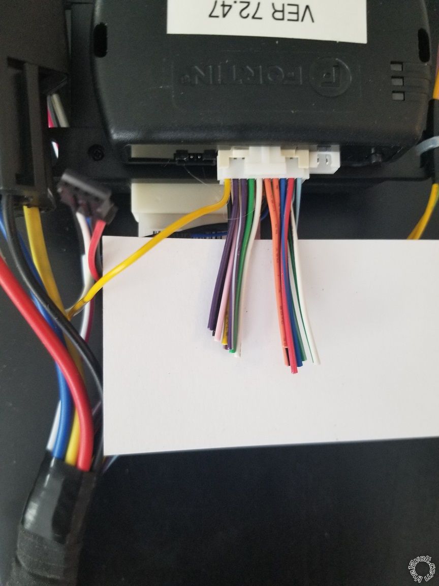
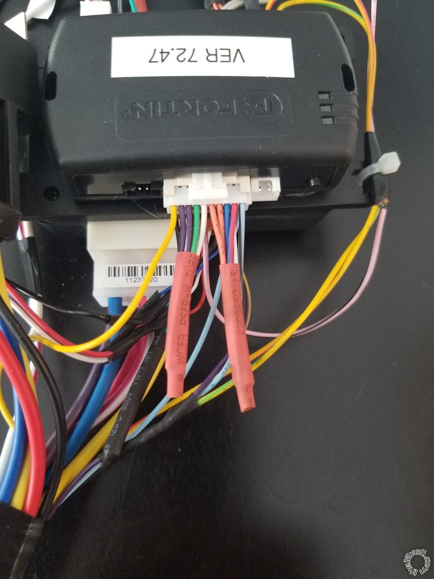
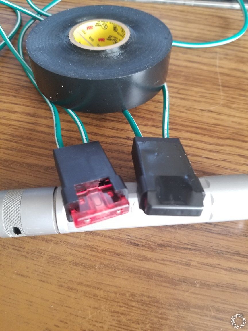
-------------
Soldering is fun!
You can cut them off to about 2 inches such that they aren't all exactly the same length. Then wrap the cut wires with Scotch Super 33+ tape past the wire tips. With the wires cut to very slightly dis-similar lengths there is less chance that any of the ends will touch each other and cause problems and with the tape past the wire ends no chance of touching anything under the dash.
Additionally, I tape a length of Supper 33+ from the sides of the fuse holders and over the top of the fuse, not to secure the fuse in the holder but to insulate the slightly exposed fuse tips that you use to test the fuse in place. I have seen instances when these exposed fuse ends touch a piece of metal bracket under the dash and blow.
Some photos :
-------------
Soldering is fun!
Posted By: firefighter1466
Date Posted: February 08, 2021 at 1:24 PM
Thanks Kreg for all your help. You've been fantastic and it's working like a charm and all taped up, mounted and good to go! Now on to my car audio, haha! I just created a new post a few hours ago over in that area. Hopefully there's someone on that end that's half as helpful as you have been on this and I know I'll be in good hands!
-------------
Jon
-------------
Jon