2009 Nissan Xterra, Viper 4806V Remote Start
Printed From: the12volt.com
Forum Name: Car Security and Convenience
Forum Discription: Car Alarms, Keyless Entries, Remote Starters, Immobilizer Bypasses, Sensors, Door Locks, Window Modules, Heated Mirrors, Heated Seats, etc.
URL: https://www.the12volt.com/installbay/forum_posts.asp?tid=146764
Printed Date: May 02, 2026 at 12:49 PM
Topic: 2009 Nissan Xterra, Viper 4806V Remote Start
Posted By: detergentcandy
Subject: 2009 Nissan Xterra, Viper 4806V Remote Start
Date Posted: March 13, 2021 at 2:27 PM
Greetings!
I was hoping to get some answers before I start this install.
I have a 2009 Xterra with M/T. Vehicle has a chip key.
I purchased a Viper 4806V remote start system and a Directed DB3 bypass module based on recommendations from the Xterra forums. However, actual install walk-throughs don't seem to exist. I know I'm capable of doing the install myself, but I would still like some form of walk-through or some diagrams if possible.
1. Will I need to use any other wires than what is listed here?
There are a lot more wires in the Viper harness than what is in the thread I linked. I assume those are just not used for the install?
2. Will the DB3 module allow the car to remote start even without the key present? I assume this is the purpose of the "bypass" module. Or will I still need to sacrifice a key to keep inside the car near the ignition for the remote start to work?
3. My research says that my transmission has a neutral safety wire coming off it which is what the computer uses to tell the transfer case that the transmission is in neutral for 4WD. Can I use this wire to install the remote start like you would in an automatic transmission so that I don't have to go through the manual transmission "shut down" procedure each time?
Replies:
Posted By: kreg357
Date Posted: March 14, 2021 at 8:25 PM
"1. Will I need to use any other wires than what is listed here?"
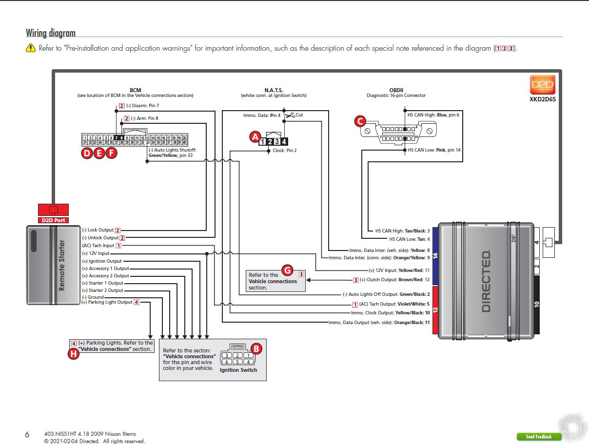
It depends... Does the vehicle have the factory alarm system? Was the DB3 flashed with the 403.NISS1HT v4.20 firmware for your vehicle? The DB3 w/403.NISS1HT Install Guide has a more complete list of required connections. Hopefully the supplier of the DB3 flashed it correctly and supplied you with the 21 page Install Guide. The install guide does have diagrams of the vehicle connectors, etc. If yes, then the DB3 will supply the Tach, Brake, E-Brake, Hood. Trunk and Door pin signals. It will also handle the Transponder bypass, Locks, Parking Lights and Hatch release.
"2. Will the DB3 module allow the car to remote start even without the key present?"
Yes, after the DB3 is successfully programmed to the vehicle it will bypass the vehicles transponder immobilizer system during remote start-up without any key in the vehicle.
"3. My research says that my transmission has a neutral safety wire coming off it which is what the computer uses to tell the transfer case that the transmission is in neutral for 4WD. Can I use this wire to install the remote start like you would in an automatic transmission so that I don't have to go through the manual transmission "shut down" procedure each time?"
Possibly. This is a major safety issue. You must locate this wire and verify that it does indeed indicate that the manual transmission is in neutral and that it only outputs this signal when the transmission is in neutral and at no other times. If this "neutral signal" is a (-) type output, then you could connect it to the Vipers BLACK/WHITE (-) NEUTRAL SAFETY /PARKING BRAKE INPUT wire.
What you are missing...
Clutch bypass - the DB3 has an output for this and the vehicle wire is indicated in the the DB3 install guide.
Accessory 2 power - the Viper 4806 can only supply 4 ignition type outputs ( ING1, Starter1, Starter2 and ACC1. If the ACC2 is required you will need a relay. The DB3 install diagram shows it connected.
Two 1N4001 diodes for the Arm and Disarm wiring.
An in-line fuse holder w/fuse for the ACC2 external relay.
As far as a step by step guide, well...
1. Obtain any extra items ( diodes and relay ) plus Tesa tape, Scotch Super 33+ Electric tape, etc.
2. Make up a wire connection list for all necessary connections. If you post it, the 12V Forum members can review it and make recommendations.
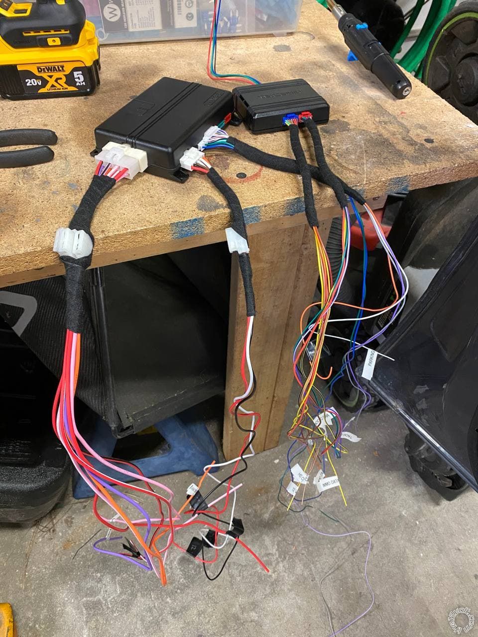
3. Bench Prep the system / modules. Cut unused wires to 3 inches and bundle/insulate. Bundle wires with Tesa Tape in groups by intended end location.
4. Disassemble vehicle and locate/test all needed wires.
5. Remove Viper fuses*, position Viper, run wires and cut to length. Solder all connections. Insulate all connections with electric tape.
6. Run antenna harness to windshield and install antenna.
7. Install fuses.
8. Program DB3 to vehicle successfully.
9. Make any necessary changes to the Viper Programming Option Tables.
10. Do a Viper Tach Learn.
11. Test the Vipers lock and unlock control. Test the Hatch Release.
12. Test the Viper R/S function.
13. Test the Brake shutdown.
14. Test the Hood Pin shutdown.
* I install while hot. I do not unplug vehicle connectors other than N.A.T.S. and main ignition switch connector, if needed.
-------------
Soldering is fun!
Posted By: detergentcandy
Date Posted: March 14, 2021 at 11:06 PM
"It depends... Does the vehicle have the factory alarm system?"
Yes, the vehicle does have the factory alarm system. Well, it's the immobilizer but yeah when the car is locked the little key symbol on the gauge cluster flashes.
Looks like it was flashed with 403.NISS1HT 4.18, not 4.20. But yes, it came with a Directed 21 page install guide.
Now that I look through it more thoroughly, I do see this page. I guess I only confirmed that I got the guide when I bought the DB3 but never actually looked through it.
 This is a major safety issue.
I'm definitely aware of the safety concern with a manual transmission and I'll make sure that if I can't 100% verify that it will be in neutral then I will install it the normal way and use the reservation mode for manual transmissions. I'd just like to be able to do it the other way if possible and read about that neutral wire and got excited.
Clutch bypass
I see that in the diagram. "Clutch Output"?
Accessory 2 power
Looking at that diagram, it looks like more than 4 IGN outputs are needed. Ignition Output, Acc 1 Output, Acc 2 Output, Start 1 Output, and Start 2 Output. I believe I saw a post on these forums or possibly on Youtube about how to set up the relay that's needed. But if you have notes for me that would also be helpful.
Two 1N4001
As in this guy?
An in-line fuse holder w/fuse for the ACC2 external relay.
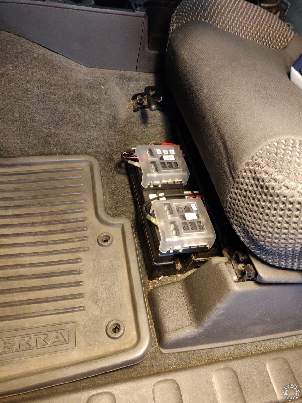
I actually installed 12V constant and 12V ignition fuse blocks under my front seat for purposes just like this!
Also, I very much appreciate your response! Thank you.
Posted By: kreg357
Date Posted: March 15, 2021 at 6:56 AM
The best way to test for a Factory Alarm system is to turn the engine off, stay seated but open the drivers door and press the inner power lock button, then close the door. Wait about 2 minutes and then open the drivers door using the inside handle. If the horn starts beeping, you have the Factory Alarm system. Having a chipped key is just a passive anti-theft device and the blinking light on the dash can sometimes be found on cars without a Factory Alarm.
Having an older version of firmware isn't usually a problem. Most of the time they do firmware updates is to support new vehicles and not to correct issues on older vehicles. With your 2009 Xterra I'm pretty sure it's been stable for a while. Just use the Install Guide that matches your firmware.
Yes, those are the diodes you need for the Arm and Disarm connections at the BCM. You could get 1N4007 diodes and use one for "coil quenching" on the external ACC2 relay, too. The 1N4007 will work for all your needs.
For the ACC2 relay, get a Bosch style 30/40 Amp SPDT relay with 5 pin harness and wire it like this :
Relay Pin 85 to Viper thin wire (-) Accessory Output
Relay Pin 86 and 87 to +12V constant fused at 20 Amps
Relay Pin 30 to vehicle Accessory2 wire at main ignition switch harness
Relay Pin 87A not used - insulate
That's a nice setup for power under the front seat! :star: Excellent idea and well executed.
-------------
Soldering is fun!
Posted By: detergentcandy
Date Posted: March 16, 2021 at 5:01 PM
kreg357 wrote:
The best way to test for a Factory Alarm system is to turn the engine off, stay seated but open the drivers door and press the inner power lock button, then close the door. Wait about 2 minutes and then open the drivers door using the inside handle. If the horn starts beeping, you have the Factory Alarm system. Having a chipped key is just a passive anti-theft device and the blinking light on the dash can sometimes be found on cars without a Factory Alarm.
Yes, those are the diodes you need for the Arm and Disarm connections at the BCM. You could get 1N4007 diodes and use one for "coil quenching" on the external ACC2 relay, too. The 1N4007 will work for all your needs.
Okay maybe I don't have the factory alarm cause I did that and no honking horn.
So just to confirm, I can use the 1N4007 in plae of the 4001?
We've had a hell of a blizzard in Denver so I haven't had time to check that neutral wire but I'll hopefully get started on the harnesses soon.
Posted By: kreg357
Date Posted: March 16, 2021 at 5:57 PM
Yes the 1N4001 and 1N4007 can be used for both purposes. The only difference is the higher voltage capability of the 1N4007.
Here is an excerpt from Electrosome :
Peak Repetitive Reverse Voltage of 1N4001 is 50V while that of 1N4007 is 1000V. RMS Reverse Voltage of 1N4001 is 35V while that of 1N4007 is 700V.
Typical Junction Capacitance of 1N4001 is 15pF while that of 1N4007 is 8pF.
-------------
Soldering is fun!
Posted By: detergentcandy
Date Posted: March 17, 2021 at 12:27 PM
Great, thanks! Looks like I already have a free 40/60amp relay mounted with lead wires so I'll just use that. Guess all I need to get started is the diode and some extra wire since all I have is spools of 14awg.
Posted By: detergentcandy
Date Posted: April 11, 2021 at 8:03 PM
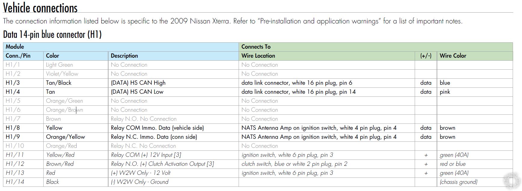
Okay so based on the DB3 install instructions, can I effectively ignore any of the connections that are not bolded? I assume my vehicle is going to be using the D2D connections and not the W2W ones. Obviously I can ignore the "no connection" ones. But I'm not sure why some of them are bolded and others are not.
Posted By: detergentcandy
Date Posted: April 22, 2021 at 12:30 AM
kreg357 wrote:
Yes the 1N4001 and 1N4007 can be used for both purposes. The only difference is the higher voltage capability of the 1N4007.
Here is an excerpt from Electrosome :
Peak Repetitive Reverse Voltage of 1N4001 is 50V while that of 1N4007 is 1000V. RMS Reverse Voltage of 1N4001 is 35V while that of 1N4007 is 700V.
Typical Junction Capacitance of 1N4001 is 15pF while that of 1N4007 is 8pF.
In the wiring diagram, which direction should my diode be facing? Should the cathode be towards the vehicle or toward the remote start?
Posted By: kreg357
Date Posted: April 22, 2021 at 5:34 AM
From the previous April 11th question, I would follow the diagram. The actual pin by pin info chart provided is very complete to cover all possible install types.
Diode use : If there are no wires in the indicated ARM and Disarm locations at the BCM connector, use the diodes and have the band towards the Viper 4806V controller. Try to Zip tie the diodes/Viper wires to an adjacent BCM wire to provide a secure and stable connection.
-------------
Soldering is fun!
Posted By: detergentcandy
Date Posted: April 22, 2021 at 10:18 AM
kreg357 wrote:
From the previous April 11th question, I would follow the diagram. The actual pin by pin info chart provided is very complete to cover all possible install types.
Diode use : If there are no wires in the indicated ARM and Disarm locations at the BCM connector, use the diodes and have the band towards the Viper 4806V controller. Try to Zip tie the diodes/Viper wires to an adjacent BCM wire to provide a secure and stable connection.
Thank you! What if there ARE wires in the Arm and Disarm locations?
If there are no wires, then I basically shove the diode into the socket like a pin?
Posted By: kreg357
Date Posted: April 22, 2021 at 10:48 AM
Yes, that is what the diodes are for, they fit pretty well into the socket for a decent electrical connection. Just secure them with a tie wrap to an adjacent wire as they can be easily pulled out. I usually tin the diode legs with some solder to provide a little extra thickness and grip. If there are wires in those locations, you can still use the diodes - they won't hurt anything.
-------------
Soldering is fun!
Posted By: detergentcandy
Date Posted: April 24, 2021 at 3:40 PM
kreg357 wrote:
Accessory 2 power - the Viper 4806 can only supply 4 ignition type outputs ( ING1, Starter1, Starter2 and ACC1. If the ACC2 is required you will need a relay. The DB3 install diagram shows it connected.
I'm trying to figure out which of these wires I need to be connecting. Here's what the DB3 bypass diagram shows should be connected.
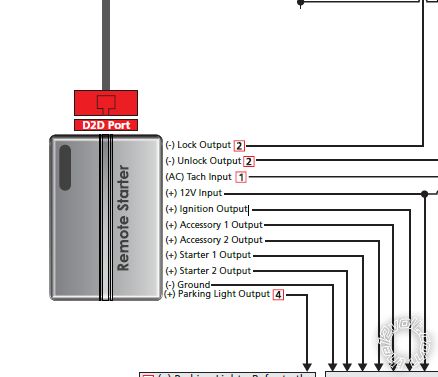
And here's the Viper wire connections list. I've added in red what I think some of them are supposed to be, but looks like I'm still missing ACC2 and Starter2.
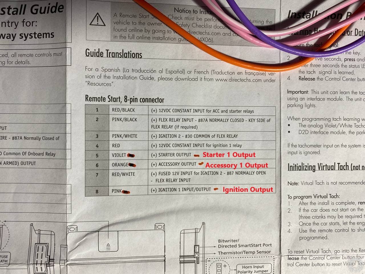
Now it does look like the Red/Black wire (12VDC Constant input for ACC and starter relays) is what I would connect to 86 and 87 on the relay, yes? Or is that incorrect because it says it's input, and I need to connect 86 and 87 to 12V output?
Posted By: detergentcandy
Date Posted: April 24, 2021 at 4:44 PM
Good news today is I confirmed the trans neutral safety switch is (-) when in gear!
Neutral
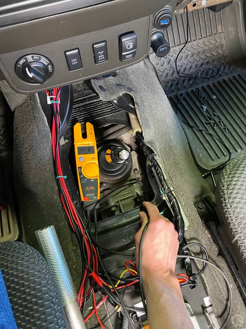
2nd
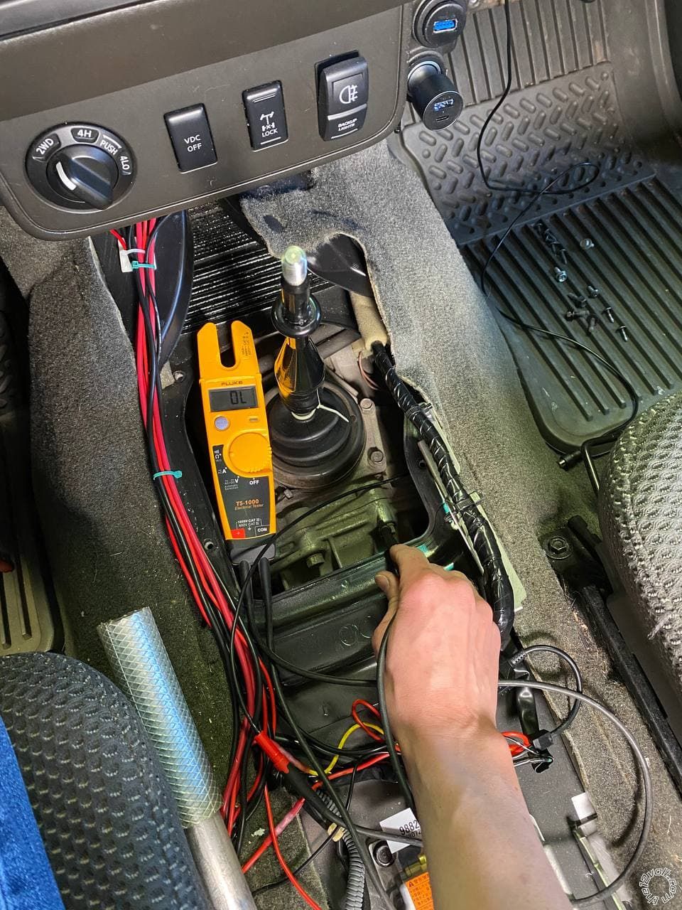
So the only thing left I still need to figure out is the ACC2 and Starter2.
Posted By: kreg357
Date Posted: April 24, 2021 at 5:39 PM
Here are the connections for the 8 Pin ignition harness. It covers everything except the ACC2 wire.
Pin Color Function connect to
1 Red/Black +12V Input +12V Constant
2 Pink/Black 87a not used
3 Pink/White Flex Starter 2 *Program Viper Flex relay = Starter
4 Red +12V Input +12V Constant
5 Violet Starter Starter 1
6 Orange ACC ACC1
7 Red/White +12V Input +12V Constant
8 Pink Ignition Ignition
For the ACC2 wire, use the 30/40 Amp SPDT relay with inline fuse holder as follows :
Relay Pin 85 to Viper thin Orange wire labeled (-) Accessory Output
Relay Pin 86 and 87 to +12V constant through 25 Amp fuse
Relay Pin 30 to vehicle ACC2 wire
Relay Pin 87a not used - insulate
-------------
Soldering is fun!
Posted By: detergentcandy
Date Posted: April 24, 2021 at 11:34 PM
8D Thanks Kreg!
kreg357 wrote:
3 Pink/White Flex Starter 2 *Program Viper Flex relay = Starter
Do I need to program the Viper with software? Or is this something I can program after install like you do when programing functions for the remote?
Didn't get as far as I wanted today but that's mostly cause I didn't know what to do with the 8 pin ignition harness. So I just sat around and organized tools. By the time I saw your answer it was a little too late to get back into it. But I made progress on the harnesses and the relay!
Cathode side connects to 86, correct? I hope so :P
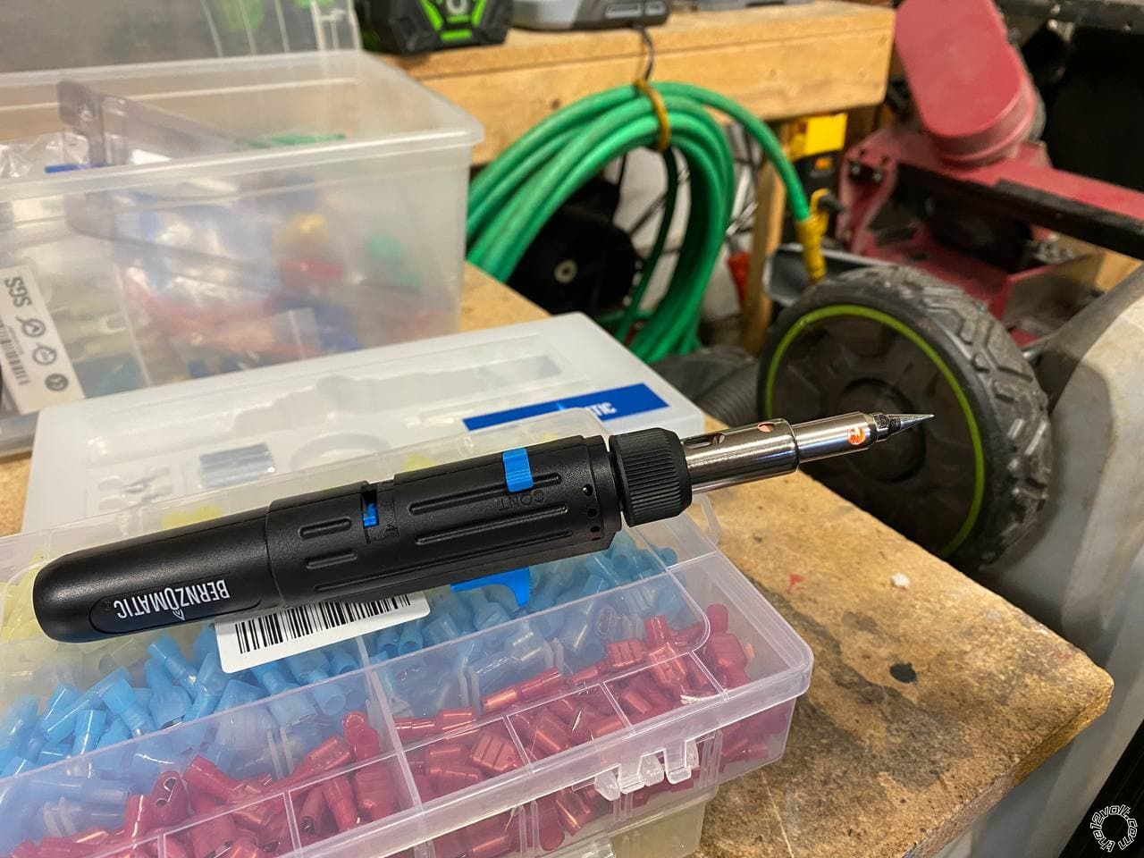
Also, I can't believe I've never owned a butane soldering iron until now. Makes soldering under a dash SO much easier when you don't have to worry about a cord.
Posted By: kreg357
Date Posted: April 25, 2021 at 3:25 AM
Yes, the Flex Relay output ( Pink/White ) can be selected via Viper programming using the supplied remotes. See Menu 3, Feature 8, Option 3 for Starter2 output. There should be programming instructions in the 2 page Install Guide. It take a little practice to get used to using the remotes to make programming changes.
Yes, again, the diode Cathode ( stripe ) goes to Relay Pin 86 if you follow the above diagram and make Pin 86 the (+) side of the relay coil. Nice work on the relay socket wiring - very clean. :^:
Looking at the 4806V Install Guide, the thin Orange (-) Accessory Output that goes to Relay Pin 85 is Pin 23 on the Aux/Shutdown 24 Pin harness. I'm sure you found that but just to clarify my earlier post.
No cord on the soldering iron makes things easier. I couldn't find a butane iron that gave me the temp control I wanted so I'm still using a Hakko FX-601 soldering iron.
-------------
Soldering is fun!
Posted By: detergentcandy
Date Posted: April 26, 2021 at 3:01 AM
I guess that's better than having to get the module programmed by a shop or distributor! I'll take a learning curve over that :P
And I do appreciate the clarification on the Acc. output.
Another question: the Parking Light Output on the remote start says it's only necessary if parking lights aren't supported in data. How can I find out if they're supported by data without installing everything first and trying it? I kept that wire long with the expectation that I would connect. But I can always trim it short if my lights are supported by data.
Posted By: kreg357
Date Posted: April 26, 2021 at 6:06 AM
Look at the DB3 Install Guide. There should be a list of supported D2D featured. While I don't have a copy with me, From the wiring diagram you posted, it appears that Parking Lights are not supported via Data. The wiring diagram shows a (+) Parking Light output from the R/S controller that is directly connected to the vehicle. The exact vehicle wire should be listed in the DB3 Install Guide in the Harness connections section.
-------------
Soldering is fun!
Posted By: detergentcandy
Date Posted: April 26, 2021 at 8:24 PM
Excellent! Found the parking lights in the kick panel and got those connected.
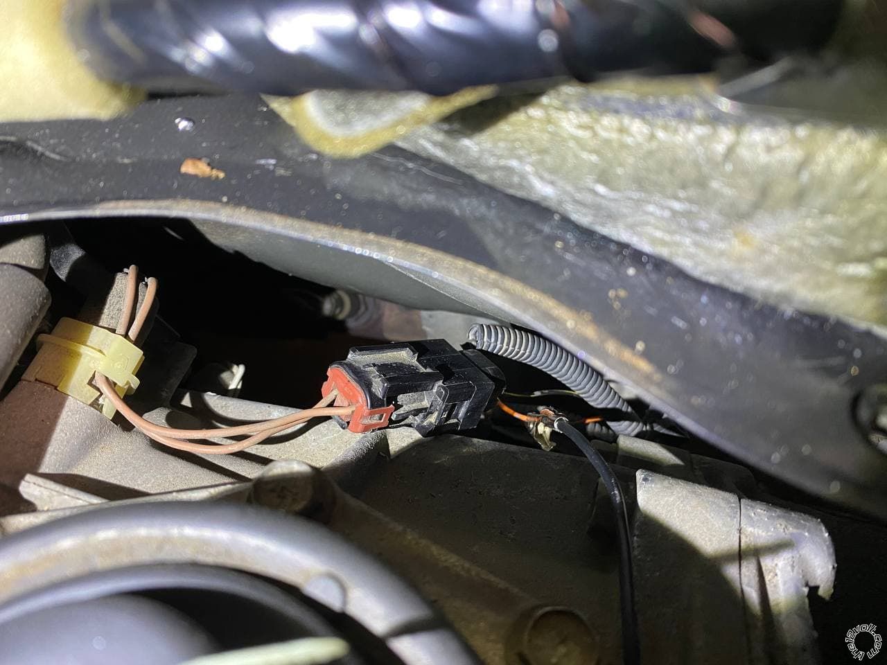
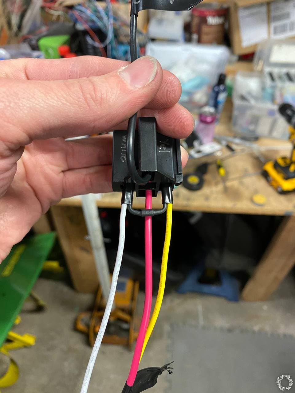
Can you explain the clutch wiring to me?
The DB3 instructions say to wire the clutch output to either 1 of the 2 clutch wires.
However, the Viper RS came with pictures of all the wire locations and in this picture it says to short both of the wires with a relay?
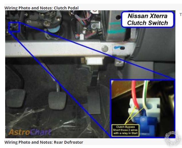
Posted By: kreg357
Date Posted: April 26, 2021 at 9:44 PM
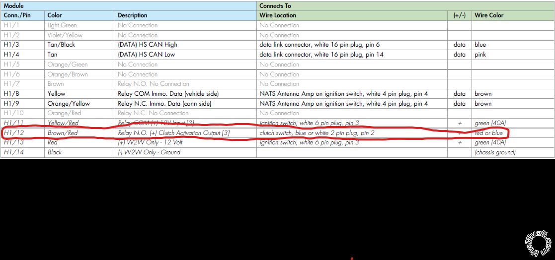
Well, you could do it that way. That info is from an old AstroChart info/photo. The White/Green wire has +12V on it and when the clutch pedal is fully depressed the interlock switch closes and the +12V is supplied to the Red wire. By using a relay to do this "fully depressed" function you achieve the same thing during a remote start. You would use a signal like (-) Status Output to control/energize the relay. However, the DB3 makes it easier for you by supplying the +12V signal at the right time on its' H1/12 Red/Brown output wire. All you have to do is connect the Red/Brown wire to the non-White/Green wire in that 2 Pin Plug. As stated, the wire could be either Red or Blue. The photo has it shown in Red. So, find that 2 Pin plug at the clutch pedal with the White/Green wire and connect the DB3 Red/Brown wire to the other ( either Red or Blue ) wire in the 2 Pin Plug.
-------------
Soldering is fun!
Posted By: detergentcandy
Date Posted: April 27, 2021 at 1:39 AM
:D I see why everyone says the bypass makes everything easier! Thanks for that info. Makes much more sense now.
Just need one more evening and I'll be done.
For the bypass I still need to wire all the NATS, and the clutch.
The ignition harness was a massive PITA. I had maybe 3 inches of wire to work with? The solder wasn't the prettiest but it seemed strong and tape hides everything :P
All that's left on the RS is the hood trigger. Didn't really know where to put the ACC2 relay so it's just zip tied to another harness. Not happy with that but it's close by in case anything needs to be replaced. Still need to wrap a lot of those wires in Tesa tape as well.
Other than the NATS, clutch, and hood, I just need to do the 12V wires.
Question: I have 3 wires from the RS that have in-line 20A fuses. Can I run all three of those to the same (+) lug on my fuse boxes and use a single 20A fuse? Should I use a 60A fuse? Or should I terminate each one at its own lug with 20A fuses at each? I have open lugs to do that but I also didn't plan on using half of them for this one install :P
Posted By: kreg357
Date Posted: April 27, 2021 at 6:42 AM
Only 3 power input wires from the Viper R/S system?
The Viper has H1/1 and from the R/S 8 Pin connector Red, Red/White and Red/Black. Add in the 20 Amp fused input to the external ACC2 relay and you have 5 wires needing +12V power. Viper H1/1 supplies power to the Viper controller logic, the (+) Parking Light output and the bypass module.
At the vehicles ignition switch, the Dark Green wire supplies power to all of the ignition wires and is rated/fused at 40 amps.
I think I would split and balance the 5 input power wires between two of your open power lugs, both fused at 40 Amps. Or you could use the vehicles Dark Green wire at the ignition switch connector as one source and save a power lug.
-------------
Soldering is fun!
Posted By: detergentcandy
Date Posted: April 27, 2021 at 12:33 PM
Yes, correct! Sorry for the late night confusion!
I have:
3 power from the R/S 8 pin connector
1 power from the relay (86 and 87) -------|
1 power from the R/S 6 pin connector ---|---- connected together into 1 power
1 power from the bypass --------------------|
I hope that makes sense? I spliced the bottom 3 together so I only actually have 4 power wires in total that need to be connected.
The R/S has 2 jumpers. The first one is for the "light flash polarity". I assume since my parking lights are (+), I jumper that one (+)?
The other is "horn input polarity jumper." I'm not connecting a horn wire, so is this something I need to worry about?
Posted By: kreg357
Date Posted: April 27, 2021 at 1:09 PM
Good plan with the +12V input power. You could connect the 3 R/S 8 Pin power inputs to one power lug and fuse at 40 amps.
Yes, your vehicle needs (+) Parking Lights so make sure that fuse/jumper is set to (+).
The Horn polarity jumper doesn't matter if you don't plan to connect that Blue wire and use the Horn Alert feature.
-------------
Soldering is fun!
Posted By: detergentcandy
Date Posted: April 27, 2021 at 2:50 PM
Hmm, I guess the question is will the horn still honk when the doors are locked like factory? I don't really care if the horn honks when the car is remote started, but I like the audible confirmation of locking the doors so I don't have to look back at the car and confirm it's locked in a parking lot.
Posted By: kreg357
Date Posted: April 27, 2021 at 4:00 PM
The horn confirmation beeps come for the H1/3 Brown (-) Horn Output wire.
Info on vehicles horn wire: Horn BROWN OR RED (-) HORN SWITCH OR DRIVER KICK PANEL in WHITE 16 PIN CONN, PIN 9
Direct connection should be fine.
-------------
Soldering is fun!
Posted By: detergentcandy
Date Posted: April 29, 2021 at 3:03 PM
Got that reextended after initially cutting it short, haha. Good to go there!
There is an orange wire on the same harness that is GWA (ground when armed). I didn't initially have this connected cause the DB3 diagram didn't mention it. Is that necessary?
UPDATE: according to this thread (https://www.the12volt.com/installbay/forum_posts.asp?tid=102418) I don't need the GWA wire.
Posted By: detergentcandy
Date Posted: April 30, 2021 at 12:12 AM
kreg357 wrote:
The horn confirmation beeps come for the H1/3 Brown (-) Horn Output wire.
Info on vehicles horn wire: Horn BROWN OR RED (-) HORN SWITCH OR DRIVER KICK PANEL in WHITE 16 PIN CONN, PIN 9
Direct connection should be fine.
Done and done!
Wrapped up the install tonight and I was partially successful.
DB3 programmed successfully.
Tach learn programmed successfully.
Key fob locks and unlocks doors.
When attempting to remote start, I get several parking light flashes in pretty quick succession, then nothing, then 5 slow parking light flashes, and that's it. I believe this is the "Brake wire is active" error. Any ideas? I reconfirmed that the black/white parking/e-brake input that I have connected to the transmission neutral safety switch is closed when the transmission is in neutral and open when in gear. So that seems to be working as I expected. But not sure why I'm getting the error...
Posted By: kreg357
Date Posted: April 30, 2021 at 8:33 AM
Well, according to the DB3 install guide, the DB3 supplies the Brake signal via the DBI D2D harness. Not much you can do there to test things.
At this point there are many possible issues.
The clutch bypass might not be working. You could a try a R/S while sitting in the vehicle with the clutch pedal depressed.
You could try a a R/S while a key was inserted but not turned in the ignition switch.
You could try a R/S with the Viper EBrake/Neutral Safety wire disconnected (and the transmission in neutral!).
You should preform the Viper Shutdown Diagnostics on it to see exactly which code is present. The steps are outlined in the 2 page Viper install guide. This will give you a better starting point.
-------------
Soldering is fun!
Posted By: detergentcandy
Date Posted: April 30, 2021 at 11:54 AM
kreg357 wrote:
Well, according to the DB3 install guide, the DB3 supplies the Brake signal via the DBI D2D harness. Not much you can do there to test things.
At this point there are many possible issues.
The clutch bypass might not be working. You could a try a R/S while sitting in the vehicle with the clutch pedal depressed.
You could try a a R/S while a key was inserted but not turned in the ignition switch.
You could try a R/S with the Viper EBrake/Neutral Safety wire disconnected (and the transmission in neutral!).
You should preform the Viper Shutdown Diagnostics on it to see exactly which code is present. The steps are outlined in the 2 page Viper install guide. This will give you a better starting point.
The clutch bypass might not be working. You could a try a R/S while sitting in the vehicle with the clutch pedal depressed. No success
You could try a a R/S while a key was inserted but not turned in the ignition switch. No success
You could try a R/S with the Viper EBrake/Neutral Safety wire disconnected (and the transmission in neutral!). No success
You should preform the Viper Shutdown Diagnostics on it to see exactly which code is present. The steps are outlined in the 2 page Viper install guide. This will give you a better starting point. I did not get any LED flashes when attempting this :/
In another forum post the user solved this issue by switching his transmission type from manual to automatic, but I've already done that. I also confirmed that the Flex Relay is set to ACC2.
Posted By: detergentcandy
Date Posted: April 30, 2021 at 12:17 PM
Could the tach input be a factor? Seems like default is "Virtual Tach." But since the DB3 does data tach, should I switch that feature from virtual tach to "Tachometer"?
UPDATE:
Unplugged all the wires from both modules except the 8-pin remote start harness.
Waited about a minute and plugged them all back in, plugging in the D2D wire last (recommended in the instruction guide).
No change.
Checked my brake switch, and it's operating normally.
Changed Tach input from "Virtual" to "Tachometer", and no change.
Changed the transmission to manual, no change.
Change it back to automatic, no change.
Still getting the 5 flash error.
Posted By: kreg357
Date Posted: April 30, 2021 at 2:44 PM
I'm not a Viper person so my experience is limited. If you are getting the 5 Blink error code and it does mean a Brake pedal shutdown, there is not too much you can do in D2D mode. If you were in W2W mode, you could temporarily delete that connection between the Viper and the DB3. I use iDatalink bypass modules and with them you can go into their settings and "turn off" the D2D Brake output if you needed to test. Not sure if that is an option with the DB3. Double check to ensure that the Viper Brake wire ( Pin 20 BROWN (+) BRAKE SHUTDOWN INPUT ) is not used and insulated.
One thing to mention. The DB3 is supplying the Viper with an E-Brake signal via the D2D harness and you are manually inputting the Transmission Neutral signal into the Viper on the Pin 13 BLACK/WHITE (-) NEUTRAL SAFETY /PARKING BRAKE INPUT wire. Not sure who wins in that case. Have you tried/tested the E-Brake wire to see if it works and is the E-Brake ON during your tests?
As for Tach :
If you are set for Manual Transmission Mode, then Engine Checking = Tach must be set and the Tach Learned successfully. You can run in Virtual Tach Mode if Auto Trans is selected. Virtual Tach is less reliable in cold climates. You could even go to Fixed as a test to see if the starter will crank.
Worst case scenario would be to switch over to W2W by removing the DBI D2D harness and making the required hardwired W2W connections including power and ground.
-------------
Soldering is fun!
Posted By: detergentcandy
Date Posted: April 30, 2021 at 3:30 PM
Still appreciate the help, even if you're not fluent in Viper! :)
I confirmed the BRAKE SHUTDOWN INPUT is not connected and is insulated/not touching anything else.
E-brake switch worked. Tried with brake disengaged, engaged, and switch disconnected. No change.
If worst case scenario, would I not only remove the DBI D2D harness but also disconnect the 2 HS CAN wires from the OBDII connector? Or do they stay connected?
As for adding in the hardwired W2W connection, aside from the 12V and ground, every single W2W connection says it connects to "Remote Starter." I'm not really sure how to define that other than I'm connected the remote start outputs to the bypass outputs which doesn't make sense.
2 oddities that I'm not sure have any relation to this.
So far, the lock button on the Viper remote works every time. But the unlock button requires 2 presses to unlock. The first time the remote chirps as if it's received and executed the command, but nothing happens. It requires a second button press to actually unlock.
And, for the tach learn. Following the instructions for Data Tach (which is the same as Hard-wired), the parking lights are supposed to flash to confirm which tach signal it learned. It's only flashing once, which means that's the hard-wired tach signal. It should be flashing the lights twice to indicated it was programed for data tach learning. So even tho the hard-wired tach signal is not connected and it should be getting the tach signal from data, it's confirming that it has learned the hard-wired tach input.
Posted By: kreg357
Date Posted: April 30, 2021 at 6:48 PM
Try programming the Viper to "Double Unlock" - Menu 1, Feature 5 to Option 2. That might get the doors to unlock with one Viper remote Unlock press all the time.
Did you make the Viper hardwire Tach connection shown in the DB3 install wiring diagram? If yes, that is why you only get one parking light flash when doing a Tach learn. The Viper should support Data Tach via the DBI D2D harness but going hardwire won't hurt things.
Did you connect the DB3 Blue Plug Pin 11 Yellow/Red wire to +12V constant? That is where the DB3 gets the +12V for the clutch switch bypass.
If you had to switch to W2W, all the connections between the DB3 and the vehicle would still remain. You would need to hardwire between the DB3 and Viper :
H1/13
H1/14
H2/5 might already be done
H2/6
H3/1
H3/2
H3/3
H3/7 maybe, if not hardwired directly from Viper to vehicle
H3/8
H3/10
-------------
Soldering is fun!
Posted By: detergentcandy
Date Posted: May 01, 2021 at 12:53 AM
Double Unlock worked. I imagine this is because the factory fob would unlock only the driver door with a single press and all the doors with a second press.
The tach wire from the DB3 is connected to the tach wire from the RS, but neither of those are connected to anywhere else.
The yellow/red 12V from the DB3 is connected along with the red 12V from the RS 6-pin connecter to the power wires for the ACC2 relay. I bundled them all together on the same 12V lug of my fuse box.
So for the W2W:
H1/13 - Any 12V
H1/14 - Ground
H2/5 - Currently connected to the RS tach input. Do I connect both of these to an injector wire?
H2/6 - RS brake shutdown input + vehicle brake wire?
H3/1 - RS ignition input + vehicle ignition wire?
H3/2 - RS Unlock output + vehicle disarm w/ diode?
H3/3 - Do I need this since it's an SUV and the vehicle unlock/lock controls the rear liftgate lock/unlock?
H3/7 - Already hardwired from Viper to vehicle. Is this needed then?
H3/8 - RS Starter output + vehicle starter wire?
H3/10 - Not sure where this one goes. RS has a GWA output, but now sure where that would go on the vehicle.
I'm sorry if I didn't understand any of that correctly.
Posted By: kreg357
Date Posted: May 01, 2021 at 7:16 AM
Before you have to change all the wiring on your neat install can you verify that the Viper Flex Relay Function is set to Starter2?
Menu 3, Feature 8, Option 3
Remind me again what happens exactly when you try a R/S. Does the instrument cluster light up? Does the starter motor crank the engine? Have someone check to see if the Brake lights are on.
My next thought would be to set the Viper for Virtual Tach, ground the BLACK/WHITE (-) NEUTRAL SAFETY /PARKING BRAKE INPUT wire, disconnect only the DBI D2D harness, put a working key in the ignition switch cylinder but not turned, put the trans in neutral, step on the clutch and try a R/S.
If that worked getting the engine to turn off before 12 minute run time ended would be difficult unless you install the Hood Pin. I'm thinking because your vehicle does not have the Factory Alarm system, it does not have a factory hood pin. If that was the case and you installed the Viper kit supplied hood pin, getting the engine to shutdown would be just a matter of opening the hood.
-------------
Soldering is fun!
Posted By: detergentcandy
Date Posted: May 01, 2021 at 6:26 PM
No change when switching the Flex Relay to Start2. Tried it on Ignition2 as well and no change. So none of the Flex Relay options makes a difference.
When I try to R/S, I get 3 sets of double flashes, followed by 5 slow flashes. No cranking, no other anything. Brake lights are not on.
Here is a link to a video I uploaded if you would like to see. Google Drive Link
Set virtual tach, grounded the BLACK/WHITE wire, disconnected one side of the D2D wire, key in the ignition, neutral, food on clutch, and still nothing.
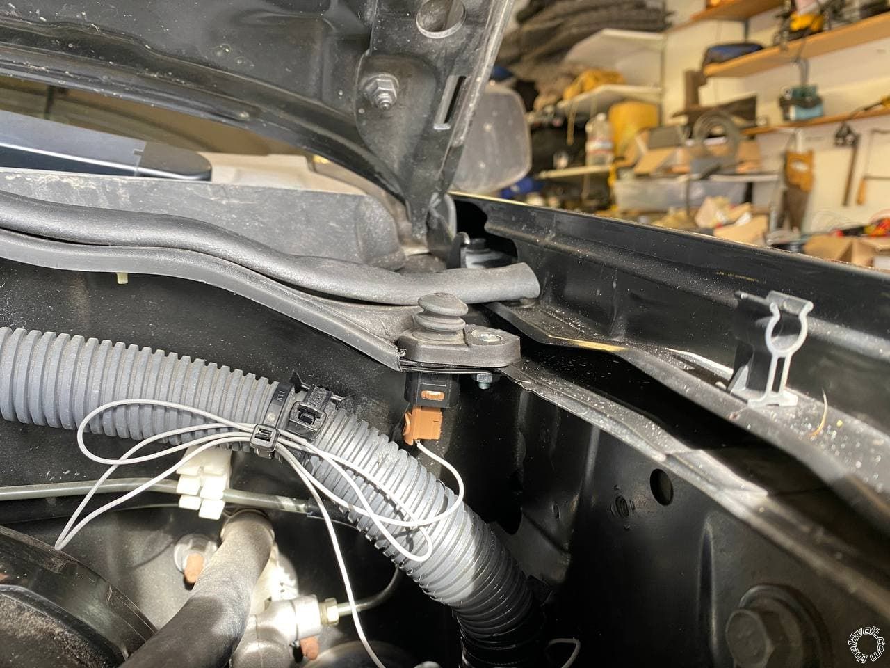
I retested my factory alarm a couple weeks ago and forgot to update. That time it did honk and flash the lights when I opened the door from the inside. I bet I didn't wait long enough the first time I tested it. So does that mean I have the factory alarm? It however does not have a hood pin, at least not visible near the latch or anywhere else. I added my own hood pin and have that connected to the hood pin wire. It's a door switch for the interior lighting and "door ajar" light from a first gen Xterra. Verified that the switch is closed when the hood is open and open when the hood is closed. Also have tested the switch with and without a heavy weight on it to make sure this isn't an issue of the hood not depressing the switch when it's closed.
Posted By: detergentcandy
Date Posted: May 01, 2021 at 9:31 PM
kreg357 wrote:
Well, according to the DB3 install guide, the DB3 supplies the Brake signal via the DBI D2D harness. Not much you can do there to test things.
At this point there are many possible issues.
The clutch bypass might not be working. You could a try a R/S while sitting in the vehicle with the clutch pedal depressed.
You could try a a R/S while a key was inserted but not turned in the ignition switch.
You could try a R/S with the Viper EBrake/Neutral Safety wire disconnected (and the transmission in neutral!).
You should preform the Viper Shutdown Diagnostics on it to see exactly which code is present. The steps are outlined in the 2 page Viper install guide. This will give you a better starting point.
SUCCESSSSSSSSS \O/
I am the smartest man alive! Or dumbest. That's up to interpretation.
I had the neutral safety switch connected to the R/S WHITE/BLACK AUX 3 OUTPUT because it looks nearly identical to the BLACK/WHITE PARKING wire.
I connected that properly and I got an actual initiation procedure, but no starter motor engagement.
My guess is while the transmission mode is set to Automatic, it does not output 12V to the clutch. Unless I'm mistaken?
So I held the clutch in and the R/S started successfully. I tried to bypass the H1/12 CLUTCH BYPASS from the DB3 by feeding the clutch wire 12V from the R/S STARTER 1. That worked but that also bypasses the clutch when starting normally with the key.
So my solution is to connect a second relay to the ORANGE ACCESSORY OUTPUT that the ACC2 relay is connected to. Use that to send 12V to the clutch. I think that should only send 12V to the clutch when using the R/S and not the key.
Alternatively I can use one of the other 200mA outputs as there are several. There's a PINK IGNITION 1 OUTPUT and a VIOLET/YELLOW STARTER OUTPUT that I think might do the same as the ORANGE ACCESSORY OUTPUT.
Would you suggest using one of those outputs? Or do you possibly have another solution to this you can suggest?
Posted By: detergentcandy
Date Posted: May 02, 2021 at 4:19 AM
It's 3 am but it's done.
I used the VIOLET/YELLOW STARTER OUTPUT from the R/S and made up a relay identical to the ACC2 and ran its power to the same terminal on my fuse box.
Everything seems to be working. Clutch still needs to be depressed when starting with a key. R/S shuts down if I put my foot on the brake without the key in the ignition, and when the hood is open.
I appreciate all of your help and input, Kreg. Thanks for sticking with me through all the back and forth! Most likely would not have finished this without you! :D
Posted By: kreg357
Date Posted: May 02, 2021 at 5:35 AM
The easiest clutch bypass solution is using a relay wired like this :
Relay Pin 85 to Viper DARK BLUE (-) 200mA STATUS OUTPUT
Relay Pin 86 to +12V constant
Relay Pin 87a not used - insulate
Relay Pin 87 to one side of Clutch pedal plug ( White/Green )
Relay Pin 30 to other side of Clutch Pedal plug ( Red or Blue )
Basically, the relay will energize at the beginning of a R/S and jump the signal across the two pins on that plug just like depressing the clutch pedal does. We don't even care what type of signal it is or on which pin it comes from. Easy peasy.
Using the (-) Starter Output will work fine also (just a shorter signal time period exactly when needed) as does supplying +12V directly to the Red or Blue wire instead of getting that +12V from the White/Green wire.
Everything seems to be working. Clutch still needs to be depressed when starting with a key. R/S shuts down if I put my foot on the brake without the key in the ignition, and when the hood is open.
That's exactly how it should be - everything should work normally with a regular key start, all the vehicle safeties should still function and the added safeties from the R/S system should be used.
Glad everything is working, nice job! Enjoy your new and improved Xterra! 8D
-------------
Soldering is fun!
Posted By: detergentcandy
Date Posted: May 08, 2021 at 2:44 AM
Okay , so small problem. I seem to be having issues where the vehicle fails to lock, even tho it seems like the remote completed the lock command successfully. When locking the doors, the remote chirps when I press lock, but nothing happens to the vehicle. This seems to happen 1 in 10 locks. Maybe a little more often even. When this happens, it will always lock on the second attempt. However, that's assuming I realize this before I walk away from the vehicle. There have been times where I got back to my car and the doors are still unlocked. Or if I'm standing right next to the car when it fails to lock, I do not even hear the locks attempting to actuate.
I have the lock pulses set to double for both lock and unlock. So I don't think that could be the issue. Is there another feature/option that might correct this that I'm just not seeing?
Posted By: detergentcandy
Date Posted: May 10, 2021 at 9:24 AM
Anyone? This just happened again last night. Parked in my driveway, turned off the vehicle, got out and pressed the lock button. Remote chirped as if it received the command, but nothing happened on the vehicle. Had to press the button again to lock the doors.
Posted By: detergentcandy
Date Posted: May 10, 2021 at 3:05 PM
I think I've figured out the locking issue but not sure how to fix it.
The failure to lock issue only seems to happen after the vehicle has been remote started and driven. So far I have not had a failure to lock during regular driving, starting, or operation.
However, if I remote start, drive the vehicle, turn the vehicle off and use the Viper remote to lock the doors, the first time does nothing, even though the remote seems to confirm that the action completed successfully. I have to press lock again in order to lock the doors.
Again, this only seems to be an issue while trying to lock the doors on the first attempt AFTER the vehicle was driven AFTER it was remote started.
Posted By: kreg357
Date Posted: May 10, 2021 at 5:47 PM
As stated, I'm not a big DEI person. Hopefully there is another member with more DB3 experience. I use iDatalink modules and usually encounter no problems. I have not done a 2009 Xterra with alarm system. Anyway, here goes.
According to the DB3 install guide, the hardwire Lock and Unlock from the Viper to the vehicles BCM is not required on some installs. So, if you haven't done it already, unplug the Viper 3 Pin lock harness and see if the DB3 CAN control works better. You might have to set the Viper back to single Unlock/Lock pulses. Next step would be to check the DB3 Feature Programming. Read the Note 2 info and verify that DB3 Feature 5 is set to Option 3 Type 2 for US vehicles. It should be as that is the Default. If it is and you are having issues, try Option 2 or even Option 1 to see what happens. I'm thinking that worst case would be to go with Option 1, hardwire Viper Lock and Unlock to the empty alarm pin positions in the BCM plug and maybe even use the vehicles Lock and Unlock wires in the DKP, too. Info below :
Power Lock violet (-) driver kick or BCM right of steering column, white 15 pin plug, pin 5
Power Unlock lt. green (-) driver kick or BCM right of steering column, white 15 pin plug, pin 6
-------------
Soldering is fun!
Posted By: detergentcandy
Date Posted: May 10, 2021 at 10:06 PM
Haha, yeah I was hoping I would get help from someone more experienced with DEI but I don't think anyone else is paying attention to this thread. And I tried to start a different thread about this issue but the mods combined that thread with this one, which no one is paying attention to. So that was helpful.
I figured the only way to get someone's attention was to quote reply you, so I'm sorry for dragging you back in. Help me Kreg357, you're my only hope.
I disconnected the 3 pin lock harness and the locks didn't work period. I could see the dash lights flash when I pressed the lock and unlock buttons as they do when locking and unlocking, but there was no motor actuation at all.
It's cold and wet at the moment so I'll give your other suggestions a shot tomorrow when it's warmer and more comfortable.
Again, thank you.
Posted By: detergentcandy
Date Posted: May 17, 2021 at 11:52 AM
Finally a small update. Tried the other 2 options without success though there were some minor overall function changes.
Option 1 - all locks works now with a single pulse. But still requires 2 lock presses to lock the doors after the vehicle has been remote started and the engine has been shut down.
Option 2 - same as above, only a single pulse is required to lock the doors. No change to the issue I've been having. However, the locks function a little more closely to factory in that they lock at 15 miles an hour and they unlock when you remove the key from the ignition. They did not do this with option 3.
So still, 2 lock presses is required to lock the doors after you shut the engine off AFTER it has been remote started. A single lock press works no problem when shutting the engine off after starting it manually with the key.
If I wire the lock and unlock manually and use option 1 as you suggested, what is the DKP?
Posted By: kreg357
Date Posted: May 17, 2021 at 1:30 PM
Sorry, DKP = Drivers Kick Panel
You can get the vehicles Lock / Unlock wires in either the DKP or at the BCM, which ever is easier for you. You would need to diode split the Vipers Lock and Unlock outputs for the dual connections ( Arm/Lock and Disarm/Unlock ) to prevent any "cross-talk" issues. Diodes' bands towards the Viper.
-------------
Soldering is fun!
Posted By: detergentcandy
Date Posted: May 17, 2021 at 1:52 PM
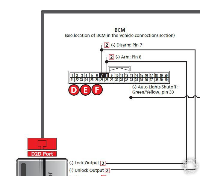
Oh, gotcha! If I already connected (with diodes) the R/S Lock and Unlock outputs to the vehicle BCM (pins 7 and 8) is what you're talking about different or the same thing?
Posted By: kreg357
Date Posted: May 17, 2021 at 2:11 PM
In that diagram above, the diodes were only used for their legs to be inserted into empty connector wire cavities. The diodes weren't really used for their signal "blocking" ability.
Here is a diagram of the diode isolation on the Vipers Lock Output wire. This would prevent a vehicle generated arm or lock pulse from affecting the other connected wire.
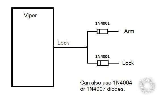
Same setup for the Viper Unlock wire going to the vehicles Unlock and Disarm wires. ------------- Soldering is fun!
Posted By: detergentcandy
Date Posted: May 17, 2021 at 2:47 PM
kreg357 wrote:
In that diagram above, the diodes were only used for their legs to be inserted into empty connector wire cavities. The diodes weren't really used for their signal "blocking" ability.
Here is a diagram of the diode isolation on the Vipers Lock Output wire. This would prevent a vehicle generated arm or lock pulse from affecting the other connected wire.
Same setup for the Viper Unlock wire going to the vehicles Unlock and Disarm wires.
That is rather interesting. So if I used diodes in those connections I made, could that possibly be the cause of my issue? I wouldn't think so because that should only be the lock/unlock output from the R/S. But I don't know a whole lot about this.
Posted By: kreg357
Date Posted: May 17, 2021 at 3:44 PM
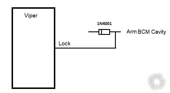
If you followed the DB3 diagram, all you really used was the diodes leg. Going by their diagram the Vipers wire was on the bare, straight leg of the diode and the Vipers signal did not pass through the diodes silicon junction. Like this :
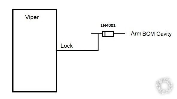
If you did connect the Vipers' output signal to to one leg of the diode and inserted the other leg into the BCM cavity, then it would only work if the diodes band was towards the Viper, which would allow the (-) signal through to the BCM. Like this :
 ------------- Soldering is fun!
Posted By: detergentcandy
Date Posted: May 18, 2021 at 11:12 AM
kreg357 wrote:
If you did connect the Vipers' output signal to to one leg of the diode and inserted the other leg into the BCM cavity, then it would only work if the diodes band was towards the Viper, which would allow the (-) signal through to the BCM. Like this :
Yeah, that's exactly what I did for both lock and unlock outputs. I guess I just got confused and thought you needed them regardless. You're saying I didn't need to do that, tho? Hahah. As long as it's not having an impact on the function of the R/S I guess I don't care.
kreg357 wrote:
Here is a diagram of the diode isolation on the Vipers Lock Output wire. This would prevent a vehicle generated arm or lock pulse from affecting the other connected wire.
Same setup for the Viper Unlock wire going to the vehicles Unlock and Disarm wires.
So this would be a "maybe" solution to my issue and then set Feature 5 to Option 1 to "disable" the bypass' Door lock control?
If, let's say, this doesn't solve the issue, can I maintain this setup and set Feature 5 to Options 2 or 3 to give control back to the bypass? That way I don't have to disconnect the new connections?
Posted By: kreg357
Date Posted: May 18, 2021 at 11:42 AM
You may have to play around with the DB3's options to see which one, if any, cures the issue.
Viper single lock / double lock / single arm / double arm might come into play, also.
-------------
Soldering is fun!
Posted By: detergentcandy
Date Posted: May 27, 2021 at 3:12 PM
I wired the R/S to both lock/arm and unlock/disarm with diodes in-line facing the correct direction and there's no change. I've tried messing around with different features on the R/S and nothing seems to fix it. The vehicle just does NOT receive the lock command on that first press of the button after it's been remote started. I just don't get it. I guess I'm going to get used to pressing the lock button twice every single time now just so I don't forget in the few times I lock it after a remote start shutdown.
|