I'm not a professional installer, but I've installed dozens of alarms and multi channel modules in my time. I've got one that's throwing my for a loop though. So I need help.
I've got a 99 Taurus. It's my daily driver. The car has power door locks, but was not built with any factory keyless parts. I want to be able to work the door locks with a remote. Don't care about the alarm portion, or light flashes, or horn honk. Just want remote door lock operation.
The car uses a lock and unlock relay under the dash, that receives a negative signal from the GEM module to activate the relays. I verified this by grounding each of the two wires, which resulted in the door locks locking and unlocking. My plan was to get a simple receiver that outputs a negative pulse, and then tap into those two wires from the GEM module to the relays.
The first unit I bought was a cheap $15 Bighawks keyless module. I wired it up and it you could hear the internal relays clicking, but nothing was being output. I figured it was just a cheap unit and wasn't working.
So I sprung for a DEI made unit, and chose the Avital 2101L. The 2101L says it has internal relays that can directly run door lock actuators. A nice feature, but I don't need to go that route since I have factory lock/unlock relays. So my plan was the same.... trigger the factory relays with a neg signal from the keyless unit.
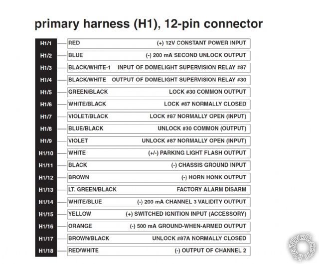
I wired the 2101L like this... H1 (red) to 12+. H5 (GN/BLK) to the lock trigger wire from the GEM to the lock relay. H8 (BL/BLK) to the unlock GEM trigger wire. H7 (P) and H9 (P/BLK) to ground. H11 (BLK) to ground.
My understanding is the relays in the 2101L work like a Bosch 5 pin. H7 and H9 are your source inputs (circuit 87, going to ground since I want the relays to output neg). H5 and H8 are your outputs (circuit 30). Circuits 85 and 85 are internal to the unit. 87A should be not used.
But when I wire it up like this, I don't seem to be getting any negative outputs to the wires going from the GEM to the lock relays.
Am I missing something here? Do I not have it wired properly to do what I want? Or should I be installing this unit a completely different way?
Thanks for any help :)
kreg357 wrote:
Try this way using the lock wires in the drivers kick panel :
Lock
H1/5 Green/Black Pin 30 PINK/YELLOW IN DRIVERS KICK PANEL
H1/6 White/Black Pin 87a not used
H1/7 Violet/Black Pin 87 Chassis Ground
Unlock
H1/8 Blue/Black Pin 30 PINK/LIGHT GREEN IN DRIVERS KICK PANEL
H1/9 Violet Pin 87 Chassis Ground
H1/17 Brown/Black Pin 87a not used
Kreg357, this is how I currently have it wired. The two wires I have it tapped into on the car are the PK/Y and the PK/LG, which are the trigger wires from the GEM to the lock/unlock relays. These wires also go to the door switches.
Strange. Can you verify that the 2101 is outputting a (-) on the H1/5 and H1/8 wires when you press the corresponding Avital remote button? Can you try using a jumper wire to momentarily put a chassis ground on the Pink/Yellow and Pink/Light Green wires to see if the locks work that way?
-------------
Soldering is fun!
I just bench tested the unit on a car battery and it is outputting a neg signal on the two output wires. I'm going to rewire it into the car again and recheck it. Possible something wasn't making good contact the first time around.
Ok, so....this pretty bizarre, but I guess it's my own fault. I was in a rush to install this unit before we closed at work the other day, and I used Scotch Locks to tap into the Pk/Y and PK/LG wires. Believe it or not, neither scotch lock was making a connection. :(
Scotch Locks, never use them but I've removed a lot of them. Nothing beats a good solder connection. Also make sure the 2101 Chassis Ground wire is to solid, clean, rust and paint free metal.
-------------
Soldering is fun!
I don't usually use them either... so I probably shouldn't have this time :oops:
It's working now :D