Viper 4806V, iDatalink ADS-TB, 2006 Toyota Matrix
Printed From: the12volt.com
Forum Name: Car Security and Convenience
Forum Discription: Car Alarms, Keyless Entries, Remote Starters, Immobilizer Bypasses, Sensors, Door Locks, Window Modules, Heated Mirrors, Heated Seats, etc.
URL: https://www.the12volt.com/installbay/forum_posts.asp?tid=147205
Printed Date: May 15, 2026 at 6:34 AM
Topic: Viper 4806V, iDatalink ADS-TB, 2006 Toyota Matrix
Posted By: putszieca
Subject: Viper 4806V, iDatalink ADS-TB, 2006 Toyota Matrix
Date Posted: January 05, 2022 at 6:03 PM
hi everyone... am looking to install remote start on my 2006 toyota matrix, manual transmission, key start, no factory alarm.
i have done my homework and almost all of them i found here 🙂
but i wanna make sure i get everything right.
what wires i only need for this install?
and what does the dashed line means on the bypass module, that's what confuses me a lot.
thank you in advance ------------- FFG
Replies:
Posted By: kreg357
Date Posted: January 05, 2022 at 10:00 PM
what wires i only need for this install?
There will be many wires needed for this install. You have chosen to install a remote starter on a manual transmission vehicle. This requires more wires. While the Viper 4806 is a manual transmission safe platform, it requires many additional things to be safely installed on a manual transmission vehicle.
Here is a list :
1. The Viper must be run in Tach Mode. This will require a hardwired Tach connection and a successful Tach Learn before the first remote start.
2. Even though the 4806 is not an Alarm system, the Door and Rear Hatch input wires must be properly connected to the car to allow entry into Reservation Mode.
3. Same goes for the vehicles Parking Brake. It must be connected to the Viper as it is also used to enter into Reservation Mode.
4. The final extra piece of the puzzle is the Clutch Pedal. It must be bypassed to allow the starter motor to crank the engine.
and what does the dashed line means on the bypass module, that's what confuses me a lot.
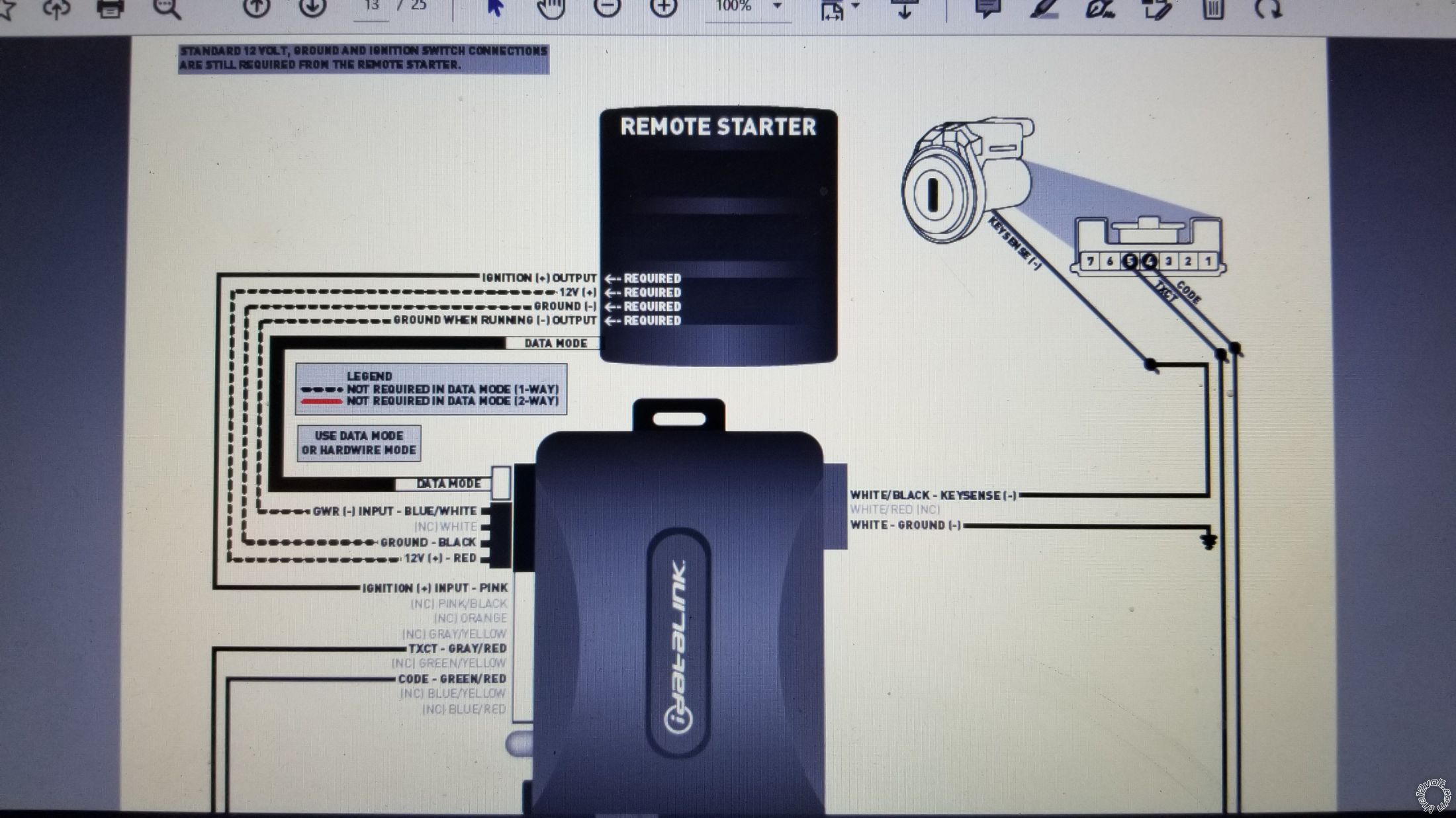
The ADS TB bypass module is used to bypass the vehicles transponder based immobilizer system. The three dashed lines are required in W2W mode. If you run the ADS TB in D2D mode they are not necessary because their function is handled by the 4 Pin Data harness connection between the Viper and the ADS TB. Of course there is a big note on the ADS TB. First, it must be flashed with the correct firmware to support your Toyota. This firmware comes in two flavors, ADS and DBI. You should flash the DBI version onto the ADS TB module to allow two way D2D communications and use the 4 Pin Data Harness. So DBI TB DL is the preferred firmware for your specific application. Second, you must set the Installation Mode to DATA prior to vehicle programming. The steps are in the DBI TB TL Guide #77711.
I would suggest listing your proposed vehicle wire connections for this install so that
the Forum members can review them and provide any needed corrections. To help, here is
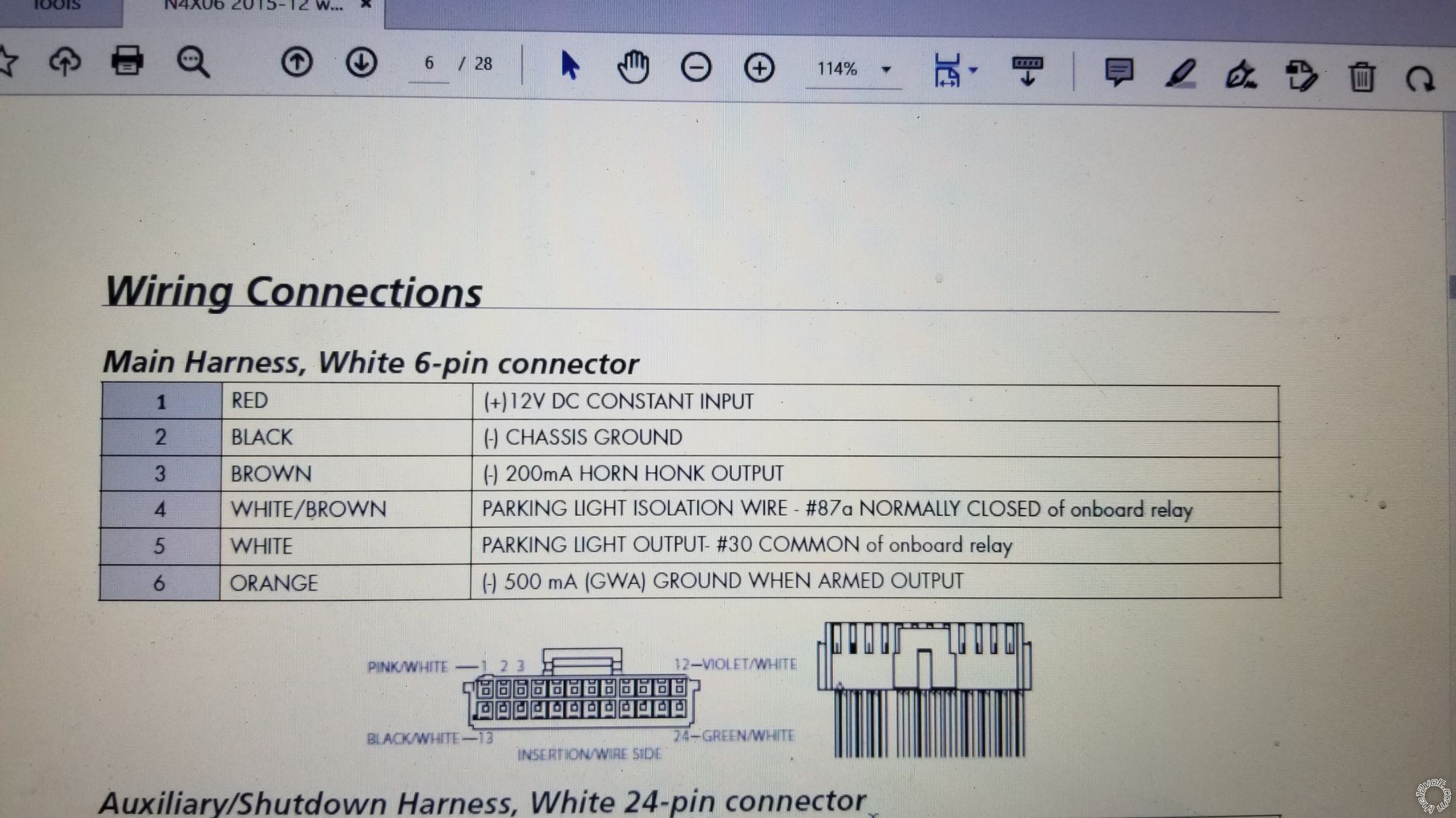
a text harness list for your 4806 :
H/1 RED (+)12VDC CONSTANT INPUT *
H/2 BLACK (-) CHASSIS GROUND *
H/3 BROWN (-) 200mA HORN HONK OUTPUT
H/4 WHITE/BROWN LIGHT FLASH ISOLATION WIRE
H/5 WHITE PIN 30 of LIGHT FLASH RELAY jumper selectable *
H/6 ORANGE 500 mA GROUND WHEN ARMED OUTPUT
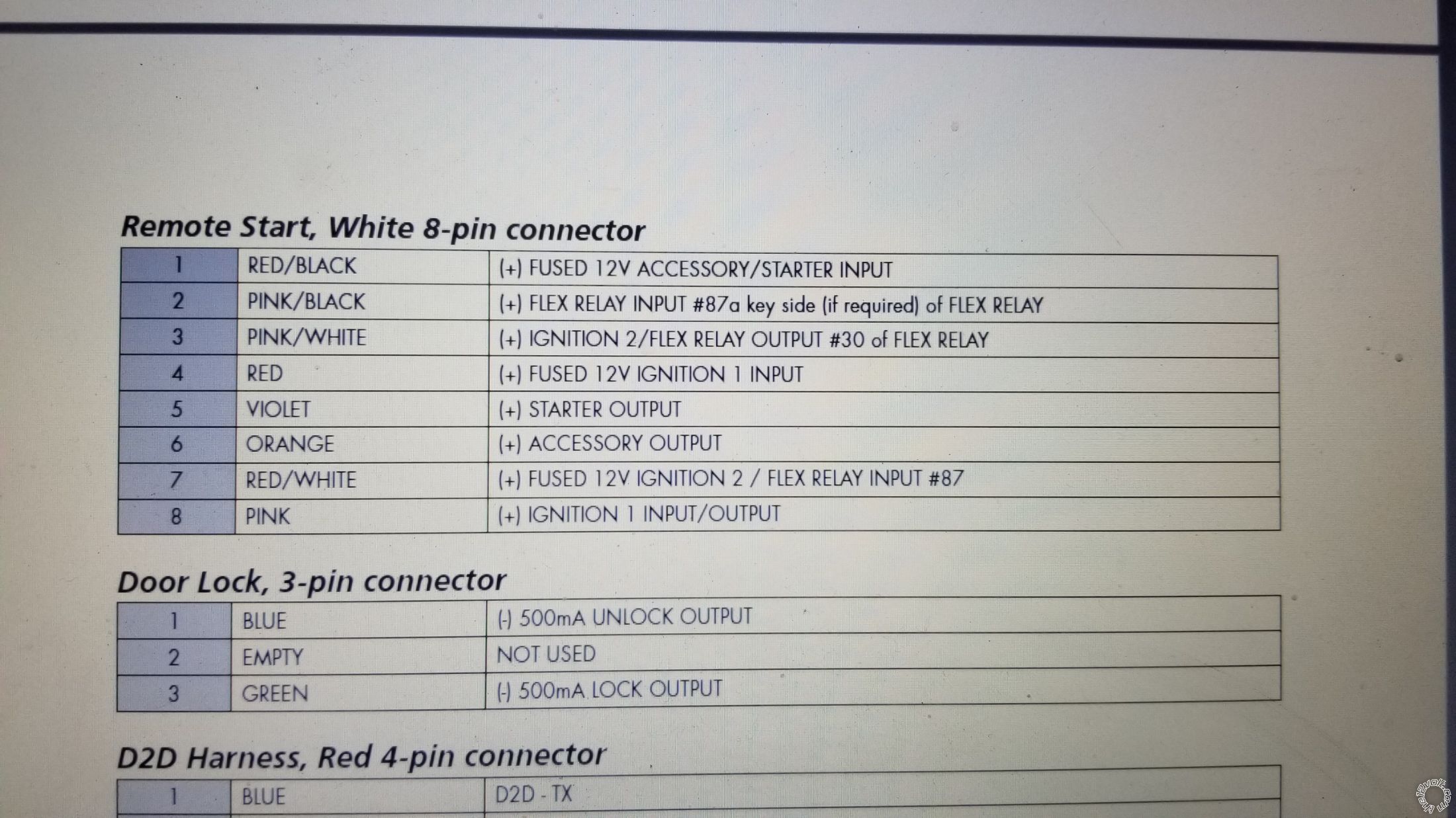
Remote Start, 8-pin connector
1 RED/BLACK (+) 12VDC CONSTANT INPUT *
2 PINK/BLACK (+) FLEX RELAY INPUT 87A
3 PINK/WHITE (+) IGNITION 2 set to IGN2 *
4 RED (+) 12VDC CONSTANT INPUT *
5 VIOLET (+) STARTER OUTPUT *
6 ORANGE (+) ACCESSORY OUTPUT *
7 RED/WHITE (+) 12VDC CONSTANT INPUT *
8 PINK (+) IGNITION 1 INPUT/OUTPUT *
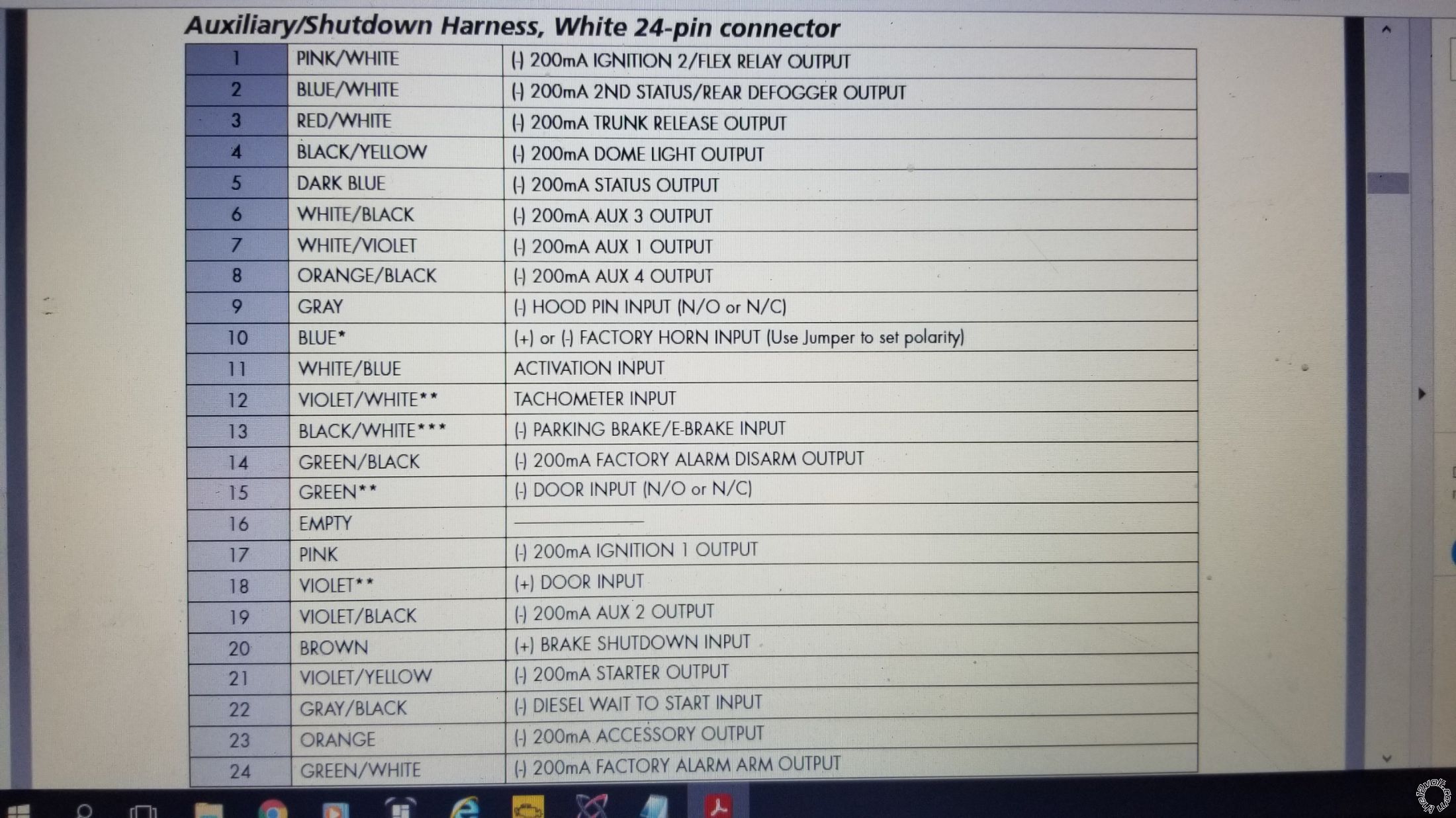
Auxiliary/Shutdown Harness 24-pin connector
1 PNK/WHITE (-) 200mA Ignition 2/Flex OUTPUT
2 BLUE/WHITE (-) 200mA 2ND STATUS /REAR DEFOGGER OUTPUT
3 RED/WHITE (-) 200mA TRUNK RELEASE OUTPUT *
4 BLACK/YELLOW (-) 200mA DOME LIGHT OUTPUT
5 DARK BLUE (-) 200mA STATUS OUTPUT
6 WHITE/BLACK (-) 200mA AUX 3 OUTPUT
7 WHITE/VIOLET (-) 200mA AUX 1 OUTPUT
8 ORANGE/BLACK (-) 200mA AUX 4 OUTPUT
9 GRAY (-) HOOD PIN INPUT (NC OR NO) *
10 BLUE FACTORY HORN INPUT (Use Jumper to set polarity)
11 WHITE/BLUE ACTIVATION INPUT
12 VIOLET/WHITE TACHOMETER INPUT *
13 BLACK/WHITE (-) NEUTRAL SAFETY / PARKING BRAKE INPUT *
14 GREEN/BLACK (-) 200mA FACTORY ALARM DISARM OUTPUT
15 GREEN (-) DOOR INPUT *
16 EMPTY ------------------------------------
17 PINK (-) 200mA IGNITION 1 OUTPUT
18 VIOLET (+) DOOR INPUT
19 VIOLET/BLACK (-) 200mA AUX 2 OUTPUT
20 BROWN (+) BRAKE SHUTDOWN INPUT *
21 VIOLET/YELLOW (-) 200mA STARTER OUTPUT
22 GRAY/BLACK (-) DIESEL WAIT TO START INPUT
23 ORANGE (-) 200mA ACCESSORY OUTPUT
24 GREEN/WHITE (-) 200mA FACTORY ALARM ARM OUTPUT
* = necessary
-------------
Soldering is fun!
Posted By: putszieca
Date Posted: January 06, 2022 at 4:03 PM
thank so much for the wiring info Kreg357
i will follow the wiring required that you provided Kreg357
i bought the viper and bypass module from lockdown security canada and had it programmed for my vehicle before it got shipped.
they gave me the guide ADS-TB-TL-EN ##77710##
instead of the DBI TB TL ##77711## though, so am thinking it was programmed as ADS-TB-TL
and on page 13 though, the dashed line requiring ground when running, 12+ and ground, on the ##77710## guide is colored red dashed line and on guide ##77711## is colored blacked dashed line...
i just dont understand how to wire it, coz its my first time to do it 🙂 thats why the way am asking is so beginnerish mode 🙂 but i am determined to install it though becoz were having this extreme cold weather now here 😫
and another thing, on the main 6 pin harness i have one 12+ constant and on the 8 pin remote start harness i have three 12+ constant, so i have two 12+ constant source on the ignition switch, a 25A and a 15A, so any suggestion if i split the four constant wire into two which of the four should i join together to tap on each of the two constant wire source? thank u in advance 🙂🙂🙂
my plan is to hooked it all up on the 25A source but change my mind when i red a post about it here in the forum
 ------------- FFG
Posted By: kreg357
Date Posted: January 07, 2022 at 8:09 AM
If they did flash the ADS TB with the ADS TB TL version of firmware you will not be able to go D2D using the 4 Pin harness. You can still use the ADS TB as flashed but must go W2W. That is easy to do. You just hardwire the black dashed lines between the ADS TB and the Viper. The Red +12V wire will get +12V constant power from the same source as the Vipers other Red fused wires. The Black wire will go to Chassis Ground along with the Vipers H/2 Black wire. The Blue/White GWR wire will be connected to the Vipers Dark Blue (-) Status Output wire at Pin 5 on the 24 Pin harness.
Other ADS TB wires :
White to same Black Chassis Ground wire.
Pink to Viper thick Pink (that goes to the Matrix Black/White Ignition 1 wire).
The other 3 wires are shown in the ADS TB TL Type 2 diagram.
Remember that to use the ADS TB in W2W Mode, you must set the Installation Mode to STANDARD HARDWIRE MODE. That is two Blinks and lock it in. This is shown at the top of the Type 1, 2 & 5 module programming page. The best way to do this is to start with a Factory Reset. After Step 5, the module is Factory Reset and the LED wil start doing a "one Green Blink" pattern. Press the modules' programming button once and the LED wil start doing a "two Green Blink" pattern. At this point just press and hold the Programming button. The LED will turn solid Green for 2 seconds and then go out. Release the button. The module is now set to W2W Mode and all ready for vehicle programming.
Viper fused +12V power input wires : While you can combine them in this vehicle application, remember that the ignition plug has two +12V power input wires used to supply the vehicles ignition wires needs. One is 25 Amps and the other is 15 Amps. That means the Vipers three ignition fused 12V input wires need 40 Amps and the other Viper Red +12V input wire needs 15 amps. I think I would locate the very thick ~140 Amp +12V input wire at the vehicles fuse box and use that to supply some of the Vipers needs.
-------------
Soldering is fun!
Posted By: putszieca
Date Posted: January 07, 2022 at 3:12 PM
now it became easy 😁😁😁
thank u so much Kreg357
i will update how it will go tomorrow
actually when i was searching info on how to do install the whole thing, i actually thought the dashed lines are not needed 😁😁😁
 ------------- FFG
Posted By: kreg357
Date Posted: January 07, 2022 at 4:00 PM
It's an either / or situation. W2W or D2D
The dashed lines would not be needed if you were able to use the 4 Pin Data Harness (D2D Mode) between the Viper and the ADS TB but with the ADS TB TL firmware loaded, you must go W2W.
Do you have the necessary diodes for the Door / Rear Hatch trigger inputs and a relay for the Clutch Bypass during a R/S?
------------- Soldering is fun!
Posted By: putszieca
Date Posted: January 07, 2022 at 7:11 PM
Do you have the necessary diodes for the Door / Rear Hatch trigger inputs and a relay for the Clutch Bypass during a R/S?
Oh no, wait...
no i don't have it yet?
what kind diodes do i need and relay?
and how do i wire them?
thanks you
-------------
FFG
Posted By: kreg357
Date Posted: January 07, 2022 at 8:04 PM
As mentioned above, installing a R/S system on a manual transmission has special requirements. These extra needs are to ensure safety during a remote start. Currently, to start the engine you use a key and depress the clutch pedal. You won't be in the Matrix during a remote start to depress the clutch pedal. This requires a clutch interlock safety bypass. Running the Viper in the Manual Transmission Mode ensures that the vehicle is in Neutral when the engine is shutdown and the vehicle is exited. The Viper will lock the doors and shutdown the engine. The Viper has now entered Reservation Mode. The Viper will then monitor all access points and exit Reservation Mode if any access point is opened. This is to verify that the transmission is still in Neutral and the engine is safe to start.
To monitor all access points you must wire up the vehicles Door Trigger pins and the Rear Hatch trigger pin to the Viper. The Vipers uses these signals to enter Reservation and then to make sure there was no vehicle entry prior to a remote start. Depending on how you wire it up you could need 5 diodes for proper circuit isolation. You will need 1N4001 diodes for this. Read up on diodes and door trigger isolation. Additionally, the Vipers' Neutral Safety Input wire must be connected to the vehicles Parking Brake wire. The engagement of the Parking Brake is part of Reservation Mode. The final part is the actual Clutch Bypass. This must be wired so that that it only happens during a remote start and has no effect on normal operation. Depending on how you wire it up, a relay might be needed for the Clutch Bypass. As you can see this is a lot of extra work and extremely important to prevent vehicle damage and personal injury/death. Serious stuff and the main reason some professional installers won't do manual transmission vehicles.
-------------
Soldering is fun!
Posted By: putszieca
Date Posted: January 07, 2022 at 9:25 PM
*Sorry, i duplicated my post a few times*
so, is all door gonna be hooked to the viper for monitoring purposes? if that so, how do i wire it? thanks you
-------------
FFG
Posted By: kreg357
Date Posted: January 08, 2022 at 4:19 AM
If you can locate that "All Door" trigger wire, then yes you can use that. Or you can use the four individual door pin wires to monitor the doors. If the Matrix has a rear Hatch that has a separate glass that opens and the whole hatch that opens, there will be two wires (Glass and Hatch) to monitor. These will be combined with diodes to provide the Viper with one isolated Door Pin input on the Green (-) Door Pin Input wire. This will ensure that the Viper can monitor all vehicle cabin access points during Reservation Mode (so there is no way the shift lever can be moved out of neutral).
Being as the vehicle uses standard (-) door pins, you can use a Digital Multi Meter to locate these pins and also test/verify the diode isolated input wire will provide a good signal to the Viper if any access point is opened.
1. Set the DMM to 20V DC.
2. Connect the Red test lead to +12V constant.
3. Connect the Black test lead to the suspect wire.
With the door/rear glass/rear hatch being tested closed, the DMM will read 0V. With the door/rear glass/rear hatch open, the DMM will read +12V. If you use the "All Door" wire instead of the individual door pin wires, then you will try each door to make sure the DMM goes to +12V when opened. The same test can be used once the necessary pin wires are combined using 1N4001 diodes into one wire for the Viper to use. The 1N4001's band must be towards the vehicle (away from the Viper) on each wire used. Diagram below :
 ------------- Soldering is fun!
Posted By: putszieca
Date Posted: January 08, 2022 at 8:49 AM
that's just amazing, everything is getting clear for me now, thanks so much...
glad i have something to get diode from...
i just found out by looking at wiring diagram lockdown sec sent me that there is a wire trigger for all doors which is good, i will just have to use 2 diodes 1 for glass ?
thank you
-------------
FFG
Posted By: putszieca
Date Posted: January 17, 2022 at 6:51 PM
it took me 2 four days to work on it little by little...
finally i got all the connections i need to make except for the door trigger, i can't find it, the one from direct wire is not accurate... i hook it up anyways:
programmed the ADS to hardwire mode and programmed the key successfully
tach learned successfully
i am doing the reservation mode as follows:
neutral, depress brake then hand brake, release brake, pressed the remote start 3 secs before trying to exit the car, but it gives me 7 flashes... 😫😫😫
what am doing wrong or done wrong... thanks you in advance... its not easy at all 😫😫😫
-------------
FFG
Posted By: kreg357
Date Posted: January 17, 2022 at 8:13 PM
The Reservation Mode entry steps look correct. Remember that the Viper must see the Brake Pedal (+) Input and the Neutral Safety Parking Brake (-) Input during this process, so those wires must be connected and providing good signals.
For testing purposes, you can connect the Viper (-) Door Status Input directly to the All Door Trigger or even just the Drivers Door Trigger* until you get the diodes and find the needed wires.
The seven flashes is a Manual Mode Error. You are in Tach Mode and Tach is learned so you should be good there.
* Left Front Door Trigger red/white (-) driver kick, harness to rear
All Door Trigger red (all doors) (-) driver kick, harness to rear
This harness has many wires and probably a few Red and Red/White wires so testing with a DMM is needed. Procedure was previously listed.
-------------
Soldering is fun!
Posted By: putszieca
Date Posted: January 17, 2022 at 8:24 PM
yes, i went hunting at driver kick for those wires using DMM but am getting -12v constant 😔
i don't know if have problem with my matrix wiring 😔
thnks once again sir Kreg357
-------------
FFG
Posted By: putszieca
Date Posted: January 22, 2022 at 6:22 PM
good day good day... so i was able to find the door trigger for all doors earlier today, and tried to do reservation mode right away and boom... 😫😫😫... still 7 blinks...
i tried with doide and without but still same thing 😫😫😫 where did i go wrong?
i think am running out of determination 😔😔😔
-------------
FFG
Posted By: putszieca
Date Posted: January 22, 2022 at 8:12 PM
i was looking at the wrong location before
-------------
FFG
Posted By: kreg357
Date Posted: January 22, 2022 at 8:27 PM
Did you check/test the Brake (+) and Parking Brake (-) wires and connections. They must all work and supply the correct signals to get into Reservation Mode.
-------------
Soldering is fun!
Posted By: putszieca
Date Posted: January 22, 2022 at 9:44 PM
i will double check them tomorrow, thnks
-------------
FFG
Posted By: putszieca
Date Posted: January 23, 2022 at 2:11 PM
kreg357 wrote:
Did you check/test the Brake (+) and Parking Brake (-) wires and connections. They must all work and supply the correct signals to get into Reservation Mode.
double checked brake and parking wires and they are both good... ------------- FFG
Posted By: kreg357
Date Posted: January 23, 2022 at 2:40 PM
Here is the Reservation Mode sequence :
Manual transmission remote start
If the vehicle has manual transmission the proper steps must be followed before leaving the parked vehicle or the remote start feature is disabled.
1. Make sure the doors on the vehicle are closed.
2. Put the transmission in neutral.
3. Press on the brake in the vehicle.
4. Apply the emergency brake.
5. Release the brake pedal.
Within 15 seconds activate the remote start from the remote.
The parking lights will flash confirming that the remote start is active.
Turn off the ignition (the car should stay running when key is turned off).
Exit the vehicle.
Arm the alarm (the vehicle should shut off when arming the system).
You can now remote start the vehicle. If a door is opened or if the alarm is triggered before the next remote start activation the system will not remote start.
So from this, the All Door Pin must be connected (& Hood Pin) and working so the Viper sees all doors closed.
The Brake Pedal must be connected to the Viper so it can see the Brake Input go (+) while the engine is running.
The Parking Brake wire must be connected so the Viper can see this input go (-) while the Brake is on and the doors are closed and the engine is running.
Next the Brake Pedal is released and that Viper signal drops from +12V.
The Viper responds with flashing the Parking Lights.
At this point you can remove the ignition key. The engine should stay running.
Next you exit the car. The drivers door opens and then closes. The Viper will see the All Door signal (-) signal momentarily.
When you press Lock on the Viper remote, it will lock the doors and turn off the engine.
You are now fully in Reservation Mode and the car can be remote started. If any door is opened (or the rear hatch), Reservation Mode is cancelled.
Here is a troubleshooting routine from a 5904V Install Guide :
MTS - Manual Transmission Start diagnostics
When enabling MTS, if you get a failure notification from the remote or the vehicle fails to remain started
check for following:
Tachometer not connected or programmed.
E-brake not connected to the remote start unit. The black/white H2/2 neutral safety wire must have a ground when the parking brake is set.
Foot must be off the brake when activating the MTS mode on the remote.
Is the door open when enabling the MTS mode? If so this would cause the unit to enter Pit Stop Mode and the remote start will continue to run when arming/locking the system.
Is the door input connected? The system needs to see a door open then close after initiating the remote start.
Does the vehicle have a delayed dome light? If you are connected to the dome light wire and the dome light is staying on after arming/locking the system, the system can exit the MTS mode.
Make sure the neutral safety switch is plugged in and turned on.
Here is a troubleshooting routine from a 5901 Install Guide :
Remote start MTS mode failure
The remote emits a failure notification when trying to enable the manual transmission mode or the vehicle fails to stay remote started when the key is turned off.
Possible causes are:
Hood Open (gray wire).
Foot Brake active (brown wire).
No Parking Brake input, Black/white neutral safety wire not showing ground with parking brake set.
Tachometer is not hooked up or programmed.
The unit has not been programmed for tachometer mode
Toggle switch not installed or not in the ON position.
You should determine where the Reservation Mode sequence Mode fails.
-------------
Soldering is fun!
Posted By: putszieca
Date Posted: January 23, 2022 at 6:10 PM
noted... thanks so much...
but there's one thing i noticed though...
like on simple command for example lock or unlock, on the remote it does'nt confirm that the viper receives the command and does the command but i can hear it locks and unlocks anyway, then i watch youtube video/s and when they press lock it will light up green with 1 beep and unlock it will blink green 2 times with beep... i am not sure if it makes sense to think the brain has some factory defect...
-------------
FFG
Posted By: kreg357
Date Posted: January 23, 2022 at 6:40 PM
I'm not a big Viper installer so I'm not going to be much help with the remotes and their functions. Hopefully another member can assist in this area.
-------------
Soldering is fun!
Posted By: putszieca
Date Posted: January 24, 2022 at 12:08 AM
its all good... infact i done a lot to this install attempt with your inputs... thank you
and i just found out that the viper came with 2 remotes... one is 1 way and one is 2 way, the one am talking about not blinking green is a 1 way, now i know 😁😁😁
i don't think the 2 way will make it start but i will see tomorrow... thanks again
-------------
FFG
Posted By: iskidoo
Date Posted: January 26, 2022 at 2:46 PM
Are you sure you wired up a tested the hood pin?
-------------
Steve G
Posted By: putszieca
Date Posted: January 26, 2022 at 11:26 PM
yes i did iskidoo. thanks for joining the topic
-------------
FFG
Posted By: putszieca
Date Posted: October 05, 2022 at 1:39 PM
And after 10 mnths sir iskidoo,i found out my hood pin, i did not even adjust and it was not being pressed all the way down 🤫🤫🤫 🤣🤣🤣
I did not even tried to disconnect and try to remote. What a rookie mistake, thank to all anyway
-------------
FFG
|