Viper 5906V Door Lock Pulse
Printed From: the12volt.comForum Name: Car Security and Convenience
Forum Discription: Car Alarms, Keyless Entries, Remote Starters, Immobilizer Bypasses, Sensors, Door Locks, Window Modules, Heated Mirrors, Heated Seats, etc.
URL: https://www.the12volt.com/installbay/forum_posts.asp?tid=147266
Printed Date: May 15, 2026 at 4:26 AM
Topic: Viper 5906V Door Lock Pulse
Posted By: sgo70
Subject: Viper 5906V Door Lock Pulse
Date Posted: February 19, 2022 at 9:13 AM
Hello, I'm doing a frame up build and engine swap on a Land Rover Defender and I have installed power door locks using the 2 relay negative pulse method and Dakota Digital Actuators and everything works great. The problem I'm having is the door remote from the Viper 5906v system. I was told by tech support that it is a neg pulse but I think I have found out that one wire will pulse negative and the other will pulse 12v+. I'm trying to figure out how I would wire this in, I'm stumped.
2 Relays:
12v+ to post 86 and 87
Ground to 87A
Actuator to 30
Carling Switch ground to 85
I appreciate the help, I have a pretty good understanding of electrical basics but I'm no wizard.
Thanks
2 Relays:
12v+ to post 86 and 87
Ground to 87A
Actuator to 30
Carling Switch ground to 85
I appreciate the help, I have a pretty good understanding of electrical basics but I'm no wizard.
Thanks
Replies:
Posted By: geepherder
Date Posted: February 19, 2022 at 4:06 PM
I think it was only the older models that pulsed negative one way, positive the other. Either way it doesn't matter. You're over thinking it. If one side of the relay coil is positive 12 volts, and you apply 12 volts to the other side, nothing happens. It'll only trigger on a negative pulse. Just do this:
https://www.the12volt.com/relays/relaydiagram75.html
-------------
My ex once told me I have a perfect face for radio.
https://www.the12volt.com/relays/relaydiagram75.html
-------------
My ex once told me I have a perfect face for radio.
Posted By: sgo70
Date Posted: February 20, 2022 at 8:42 AM
Ok thanks, that's pretty much what I have except I ran the 12 V+ to both 86 terminals and the switches to 85. Does that make a difference?
When I plug into the alarm unit and try the locks it blows the fuse, sometimes I'll get it to work once then the next try blows the fuse, I guess that's why I thought it was pulsing 12v+ on the other side. I put my test light on it to see and I'm not getting it to light, not sure if it's because it's too small of a load or too quick or maybe you're right and it doesn't pulse positive.
If I wired the green and white switch legs backwards it would just operate backwards, am I right on this? Not sure what else this could be, should be so easy.
Thank You,
Posted By: sgo70
Date Posted: February 20, 2022 at 9:54 AM
Okay, I tried a few more things. When I touch a ground probe to the Viper connector the doors lock/unlock as they should so I think my wiring is okay except maybe I have them reversed.
When I use the FOB it says a door is open and it chatters until I unplug the connector.
I made sure all my door jamb switches were pressed in (ground when doors open) and now the key FOB will lock the doors when I hit unlock (wires reversed I figure) but they will not unlock and they key FOB says a door is open. I'm assuming they won't unlock (which the Viper thinks is locking) because it senses a door open. I'll swap the wires to see what happens.
Another thing is I don't have my interior dome lights in yet (waiting for connectors). They get a constant power and then one ground wire to the door jambs and another to a switch. Could this cause a problem with the door locks? I tapped the Viper into the ground wire coming off the door jamb switch, getting frustrated now lol.
Posted By: geepherder
Date Posted: February 21, 2022 at 10:43 AM
Sorry, I'm getting senile in my old age. I re-read your original post and realized you already added a power door lock system complete with switches that works properly. Now you want to add the keyless entry functionality. Unless you have diodes installed across the relay coils, 85 and 86 will be interchangeable. A test light may take too long to illuminate that it wouldn't show anything. A multimeter might give you a better indicator. My digital meters will sometimes just flash "OL" when testing pulses. An analog meter would likely give you a needle deflection which would be more noticeable.
I'm not sure which fuse you are referring to that is blowing- one you installed for the door locks or one on the Viper.
Yes, if wired backwards it should just work in reverse. I'm assuming you mean the blue wire, not the white wire.
The likely fix for your door trigger is to use diodes and combine each of the switch outputs (from the switches themselves) instead of the wire at the dome light. The BCM is likely powering the dome light when you unlock, causing the false trigger.
All you should need to do is connect the Viper's unlock output to the existing unlock wire of the system and do the same with the lock output. This is assuming it's connected as described in your original post. It should look something like this: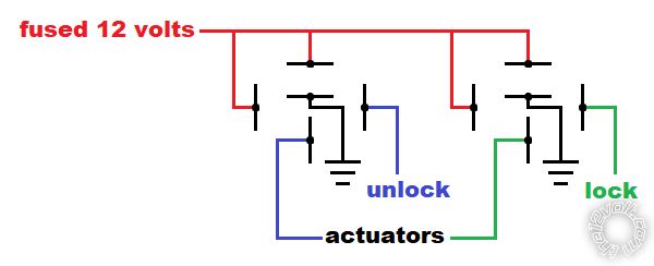
Try this and let us know if you need anymore help.
-------------
My ex once told me I have a perfect face for radio.
Posted By: sgo70
Date Posted: February 21, 2022 at 4:31 PM
Wow thanks for the explanation, I was standing by the fuel tank with a lighter lol.
I just verified I have diodes in my relays, they're actually 35amp micro relays, 280 series I think they're called. So I'm guessing I'll have to swap 85 and 86 back on the lock side since I switched the wires and it will now unlock but not lock.
Yes it was my fuse I have in the panel for the locks, that's not blowing any more, I read I need 7.5 amps/actuator so against my better judgement I went to a 30 amp fuse.
Yes I have it tapped into the switch wires and I did find one dumb mistake which I fixed, I had all my door jamb switches wired together then to the ground bar. Kinda explains why it kept saying a door was open....should've clicked seeing a blue wire going to ground.
I tried putting the meter on the Viper and when I use the FOB it looks like I'm getting a reading but it is quick, I'm going to try and phone them to confirm it does send out 12v+ as well. So another question I'm not sure of, if I put diodes on (the right way), it will block the 12v+ out but will it allow the negative pulse through?
I won't even get into my other problems, remote start not available and can't do the tach learn haha, this is getting exhausting.
I really appreciate the help, thank you,
Sean
Posted By: sgo70
Date Posted: February 21, 2022 at 4:41 PM
Actually, just thinking about it, if the door locks work fine with the switches and I have it wired up as you show above, can I just leave the relays alone? I'm wondering if the switch is overpowering the diode in the relay but maybe the Viper isn't, sorry if that's a dumb question. So to be clear:
Switch works good both lock/unlock
Viper with remote unlock with FOB
Viper will not lock with FOB
Dome light supervision wire is now disconnected
Viper is wired into switch wires
and I'm losing my mind lol.
Switch works good both lock/unlock
Viper with remote unlock with FOB
Viper will not lock with FOB
Dome light supervision wire is now disconnected
Viper is wired into switch wires
and I'm losing my mind lol.
Posted By: sgo70
Date Posted: February 21, 2022 at 5:30 PM
I switched the relays around, no change, still won't lock with the FOB. Viper was closed, I'll have to call tomorrow and go get a couple diodes.
Posted By: geepherder
Date Posted: February 22, 2022 at 4:40 PM
So, the 7.5 amp fuse, was this factory, or is this part of the harness you added for the door locks? If it's a factory fuse location, you should use a separate power source, as anything higher will overload the factory wiring. Your door locks probably draw 20 amps or more, so a 25 or 30 amp fuse is probably about right. That said, the wiring needs to be capable of safely handling that.
Just to clarify, your current setup uses two relays to work with the switches, similar to the diagram I posted, correct? You could verify your door locks are programmed to the .8 second pulse duration (should be default) and not .4 second. You could also verify output with a separate relay. Just connect 12 volts to 86 and the Viper door lock output wire to 85. The activate it with the remote. Did your relay click? Do the same with unlock.
Diodes installed across the coil are not meant to block signal in the sense you are thinking, but to prolong relay life.
-------------
My ex once told me I have a perfect face for radio.
Posted By: sgo70
Date Posted: February 22, 2022 at 7:04 PM
It's all my own wiring, 12 g GXL to all the actuators and 14 g to all the switches. The 2 relays are fed power to their own 30 amp fuse location in the fuse panel. I tend to overdo the wiring so I'm confident it'll be good lol.
I actually got a hold of a tech support guy at Viper and he confirmed only an 800milliamp negative pulse, no 12v+. He actually told me to test with a relay just as you did and it wasn't good. The unlock clicked but the lock side was dead. I think because I didn't have any diodes protecting the Viper box it might have gotten cooked when I tested out the switches, he seemed to agree. So looks like I have to chalk this up to the price of learning and get a new box. On the plus side when I called them to see if I can just order the control box the lady on the other end said she was going to try to warranty it for me, worth a try, really nice of her.
I found this document from Viper that shows exactly what I have, Type D after-market actuators, I find it odd they don't make mention of using any diodes but when I talked to him he said I should. I guess I'll add them in while I wait.
https://pdf.ampire.de/directed/Tech-Tip-1041.pdf
Thanks again,
Sean
Posted By: geepherder
Date Posted: February 24, 2022 at 1:18 AM
Sounds good. Sometimes you just come across a bad module- not super common, but it does happen. That's not your fault. I'm just curious where did you place your order? I'm surprised the Viper support even entertained the idea of dealing directly with a consumer. You usually have to go through an authorized dealer.
Also, if you search "tech tip" in the download section on this site it will give you lots of useful information. One member even posted some zip files so you can download them in bulk:
https://www.the12volt.com/installbay/downloads.asp?srch=all&term=Tech+tip
-------------
My ex once told me I have a perfect face for radio.
Posted By: sgo70
Date Posted: February 06, 2023 at 4:39 PM
Well here I am back almost a year later, sold my house packed everything up and never got to finish this. I'm set up now and got a replacement Viper 5906V and it's one of the last things I need to do before I go for an inspection. I'm really worried about ruining another module so I wanted to confirm a few things.
I got some diodes and wanted to be sure, is a 1 amp 1000v diode what I should use 1N4007, and the band closest to the Viper? I also have some others 1N5404, 1N5408, 6A100, not sure if I should use one of these 3 or 6 amp diodes.
Another thought I had, is there something else that I could have done wrong that would send power back through the Viper when the door locks are activated. I was thinking maybe I should have a relay going to the dome light circuit which I don't think I have....anything else? I've been reading everything I can find, I wish I could get ahold of an install manual that explains it better than the one in the box, seems like there's more I should know when making some of the connections, the diodes for one thing.
I really appreciate the help, I wish I could just drive it somewhere to get it done but it's not really an option. Sorry Geepherder, I just saw your last post today and was going through that link all morning.
Thanks,
Sean
Posted By: sgo70
Date Posted: February 06, 2023 at 6:14 PM
Okay, I figured I should write down what I've done like I see in a lot of the other posts, so here it is.
Main 6 Pin:
1. Red-12V+ 15amp fuse
2. Black-Ground
3. Brown-Siren output
4. White/Brown-Parking light pin 87a-not used
5. White-Parking lights-(should this go to a relay, - or +.)
6. Orange-Ground when armed-not used
Remote Start 10 pin:
1. Pink-Ign 1 to Ignition switch pink
2. Red/White-Fused ignition 2- not used
3. Orange-Accessory Output-Going to ignition switch then post 86 on accessory relay.
4. Violet- Starter side
5. Green- Key side
6. Red- Fused 30amp constant
7. Pink/White- Ignition 2- not used
8. Pink/Black- Flex Relay- not used
9. Red/Black- Constant Acc/start at ignition switch 30 amp fuse
10. Blank
Door Lock 3 pin: The cause of all my problems I think
1. Blue- unlock- add diode I think with white band towards Viper then to switch wire. Not sure which diode to use?
2. Blank
3. Green-lock- same as blue above
24 Pin Connector Harness: I only used the ones listed below:
4. Black/Yellow-Dome Light(-)- should I use a relay or a diode here?
9. Grey- Hood Pin- Is this required, I don't have it hooked up yet.
11. White/Blue- Activation Input- Is this req'd?
12. Violet/White- Tach wire- not sure of this, I have swapped in a GM Gen 5 LT engine, can I use virtual tach or do I have to go to the ECM or a tach wire?
13. Black/White- NSS or Park Brake- I have it to the NSS on the shifter, I'll have to test it.
15. Green- Door Input (-)- is this req.d, not sure where this goes
16. Brown/Black- Horn (-)- goes to relay
20. Brake Shut-down- I have this to the cold side of the brake pressure sensor.
That's all I got, I'd really appreciate more help.
The door locks are run off two relays as per the wiring diagram here with Carling switches giving the (-) pulse. They all work well without the Viper connected. I also have the truck running now and everything else works properly although I haven't attempted a remote start but I have set off the alarm a number of times lol.
Thank you,
Sean
Posted By: sgo70
Date Posted: February 06, 2023 at 8:46 PM
Sorry for posting to myself again but the more I think about it there shouldn't be any way that the door locks would be getting 12v+ from the door lock relays is there? It must be coming from somewhere else, maybe the dome light or park lights, I assume they flash when the door locks are activated? I wonder if the door switch failure on the Viper was just a result of something else I messed up....
Sean
Sean
Posted By: geepherder
Date Posted: February 07, 2023 at 6:51 PM
sgo70] wrote:
I got some diodes and wanted to be sure, is a 1 amp 1000v diode what I should use 1N4007, and the band closest to the Viper? I also have some others 1N5404, 1N5408, 6A100, not sure if I should use one of these 3 or 6 amp diodes.
1 amp diodes will be fine. To be clear, I was referring to installing them across the relay coils. The banded side would go towards the coil's positive source and the other would go to the coil's ground.
sgo70] wrote:
Another thought I had, is there something else that I could have done wrong that would send power back through the Viper when the door locks are activated. I was thinking maybe I should have a relay going to the dome light circuit which I don't think I have....anything else? I've been reading everything I can find, I wish I could get ahold of an install manual that explains it better than the one in the box, seems like there's more I should know when making some of the connections, the diodes for one thing.
This should have nothing to do with the door locks.
-------------
My ex once told me I have a perfect face for radio.
Posted By: sgo70
Date Posted: February 07, 2023 at 7:06 PM
Hello again, thanks for the reply. I put in relays with diodes do I still need those ones? I also put diodes with the band towards the alarm on the door lock wires as per the Viper tech I talked to.
I've been reading all through this site finding things I didn't even know were on here. I think, if I understand correctly, the door trigger wire can connect to my door switches wire with a diode, band facing the switch wire and that should be it.
Also, I had the dome light wire from the alarm connected directly to the neg wire for the three dome lights and I'm suspecting that may have cooked the last alarm. This time I'm adding a relay with this wire going to post 85 with a diode towards the alarm, 12v+ to 86, the ground wire to 30 and 87 to a ground. I hope it's right.
I'm trying to add in the hood pin, I wish I didn't have to it's a tough one to figure out where to put it given the hood construction. I still have to find the tach wire but that shouldn't be too hard, just need batteries for my other multimeter.
That just leaves the parking lights, I have to trace it back and see if I connected that wire to a relay or not. This is hard enough as it is, let alone waiting almost a year to complete it.
Thanks again,
Sean
Posted By: geepherder
Date Posted: February 07, 2023 at 7:42 PM
sgo70] wrote:
Okay, I figured I should write down what I've done like I see in a lot of the other posts, so here it is.
Main 6 Pin:
1. Red-12V+ 15amp fuse
2. Black-Ground
3. Brown-Siren output
4. White/Brown-Parking light pin 87a-not used
5. White-Parking lights-(should this go to a relay, - or +.)
6. Orange-Ground when armed-not used
5. Polarity will be based on the position of the Viper's internal parking light fuse (under the sliding door). Many applications will not need a relay.
sgo70] wrote:
Door Lock 3 pin: The cause of all my problems I think
1. Blue- unlock-
2. Blank
3. Green-lock-
1. Blue- to the negative trigger wire for unlock
3. Green- to the negative trigger wire for lock
sgo70] wrote:
24 Pin Connector Harness: I only used the ones listed below:
4. Black/Yellow-Dome Light(-)- should I use a relay or a diode here?
9. Grey- Hood Pin- Is this required, I don't have it hooked up yet.
11. White/Blue- Activation Input- Is this req'd?
12. Violet/White- Tach wire- not sure of this, I have swapped in a GM Gen 5 LT engine, can I use virtual tach or do I have to go to the ECM or a tach wire?
13. Black/White- NSS or Park Brake- I have it to the NSS on the shifter, I'll have to test it.
15. Green- Door Input (-)- is this req.d, not sure where this goes
16. Brown/Black- Horn (-)- goes to relay
20. Brake Shut-down- I have this to the cold side of the brake pressure sensor.
4. Black/Yellow- This is not a required connection. If you're not sure whether you need a relay or not, use one.
9. Grey- It will work without it, but it's recommended. This is not only an alarm trigger, but will also shutdown the remote start if someone pops the hood.
11. White/Blue- This is not a required connection.
12. Violet/white- I prefer using a physical tach wire, but that's all up to you.
13. Black/white- If this is an automatic, you can just ground this wire since it will only start if in park or neutral anyway.
15. Green- This is connected to the negative door trigger wire(s) and is necessary for programming if you plan on changing any options without a handheld programmer (such as switching from the default manual transmission to automatic transmission). It is also used as a trigger for the alarm.
16. Brown/Black- This is commonly connected to the negative horn trigger wire in the steering column.
20. Brake Shut-down- This is commonly connected to the brake light switch above the brake pedal and should only see a positive 12 volts when the brake pedal is pressed.
-------------
My ex once told me I have a perfect face for radio.
Posted By: geepherder
Date Posted: February 07, 2023 at 7:54 PM
sgo70] wrote:
Hello again, thanks for the reply. I put in relays with diodes do I still need those ones? I also put diodes with the band towards the alarm on the door lock wires as per the Viper tech I talked to.
Yes, if you choose to diode isolate, then that would be the proper orientation.
sgo70] wrote:
I've been reading all through this site finding things I didn't even know were on here. I think, if I understand correctly, the door trigger wire can connect to my door switches wire with a diode, band facing the switch wire and that should be it.
Correct.
sgo70] wrote:
Also, I had the dome light wire from the alarm connected directly to the neg wire for the three dome lights and I'm suspecting that may have cooked the last alarm. This time I'm adding a relay with this wire going to post 85 with a diode towards the alarm, 12v+ to 86, the ground wire to 30 and 87 to a ground. I hope it's right.
This looks right.
sgo70] wrote:
I'm trying to add in the hood pin, I wish I didn't have to it's a tough one to figure out where to put it given the hood construction. I still have to find the tach wire but that shouldn't be too hard, just need batteries for my other multimeter.
That just leaves the parking lights, I have to trace it back and see if I connected that wire to a relay or not. This is hard enough as it is, let alone waiting almost a year to complete it.
Thanks again,
Sean
Post back if you need help.
-------------
My ex once told me I have a perfect face for radio.
Posted By: sgo70
Date Posted: February 07, 2023 at 8:08 PM
Wow!!! You have been such a big help, I can't thank you enough. I'm so nervous to power this up, I'm going to try to finish it tomorrow or the next day, my park light wire disappears into the rear of the fuse panel so more digging required. If I can't find it, I'll just add another relay to be safe.
So can I just leave the hood pin wire and cap it off, it appears to just open the circuit when it's depressed?
Sean
So can I just leave the hood pin wire and cap it off, it appears to just open the circuit when it's depressed?
Sean
Posted By: geepherder
Date Posted: February 07, 2023 at 10:03 PM
Yes, you can leave it disconnected for testing.
I'd also wait to connect the dome light supervision wire, too.
What year is this Land Rover?
-------------
My ex once told me I have a perfect face for radio.
I'd also wait to connect the dome light supervision wire, too.
What year is this Land Rover?
-------------
My ex once told me I have a perfect face for radio.
Posted By: sgo70
Date Posted: February 07, 2023 at 10:34 PM
Its a 2001 Defender 110 that I stripped down to the frame and swapped in a new Gen 5 GM 5.3/6l80. I dont think I even reused a single bolt lol. Its been a long few years but I actually got to drive it up onto a flat deck to get it here. If I get my wiring all cleaned up I should be able to get it on the road by spring.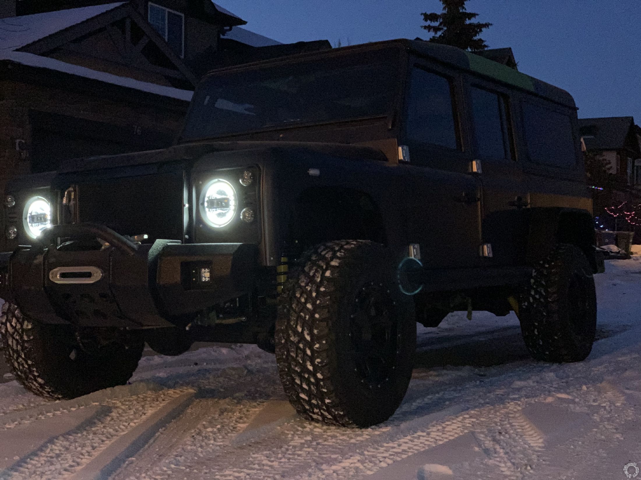
Posted By: geepherder
Date Posted: February 08, 2023 at 3:59 AM
That's a nice looking project. The parking light wire is also accessible at the headlight switch. It should be red at pin 2.
-------------
My ex once told me I have a perfect face for radio.
-------------
My ex once told me I have a perfect face for radio.
Posted By: sgo70
Date Posted: February 08, 2023 at 11:47 AM
Yeah, initially I was going to try and follow all the factory wiring and switches but Defenders are notorious for bad electrical (Prince of Darkness comes to mind). I pulled every wire from it and started from scratch, new engine harness, gauges, switches, everything. I wanted as much as I could to run off the GM canbus as I could and then I split up the electrical busses and added my own fuse boxes. A lot of the original would run full power from the switches so anytime you upgrade something like headlights etc, you burn up the switch, I added relays everywhere. To top it off switches and plugs all come from the UK and are hard to find so I converted everything to Carling and Metripak.
Anyways, I was poking around this morning and I lose the parking light wire I have connected when it comes through the firewall and up into the fuse box, I just can't get in there. I tried grounding it and nothing happens and when I turn on the parking lights via the switch with the ground still connected it blows the fuse. When I add power to it the lights come on and I can switch them on with the light switch without blowing the fuse. So I double checked that I have the fuse in the Viper on the + side and when I test the amp draw to the white wire on the Viper I'm getting 0.27amp so I'm thinking it's safe to assume this is going to a relay or that it's even low enough not to worry about going over the 10 amp limit. So I guess I can leave that wire alone.
I have an opening for a relay in my dash fuse panel so I'm going to run the dome light through there as I mentioned above, it's literally 6" away so I might as well.
Sean
Posted By: sgo70
Date Posted: February 08, 2023 at 12:23 PM
I'm not quite brave enough to put the new Viper module in yet but I decided to try out the old one to see if that helped anything.
I powered it all up and locks worked manually via the car switch, tried the remote and it locked the doors but then wouldn't do anything else, unlock or lock. I tried the car switch and it wouldn't work now either. Disconnected the battery, checked all fuses, unplugged the Viper 6 pin plug, connected battery and now the car switch works normally again........stumped.
I guess it could be something in the Viper module but, I forgot to cut the door input wire so I did that and when I connected the battery the alarm started going off and the key fob said it was the hood was open. Couldn't get it to shut off with the fob although I only tried for about 3 seconds cause my heart was at about 180bpm, really wasn't expecting that lol. I have the grey hood pin wire capped off with shrink tube. I pulled the 15amp fuse and connected the battery then put the fuse back in and the alarm kept going off even while hitting the unlock button on my fully charged fob. I tried holding it down, double tapping etc, just kept blaring away. I found that if I turn on the ignition and tap the valet key it shuts it off, finally. Wondering why neither of my key fobs are working to disarm it
Door locks still not working haha. Next I tried to hook up a relay to see if I get a click because I only have a digital MM. I got power to post 86 and the blue wire on 85, this gets weird. I press the lock button and nothing happens but it arms, press it again and nothing, won't disarm either. I connect the green to the relay and I still don't get the relay to click but I can both arm and disarm it with the fob.
Gotta look into this more. Getting very close to tossing it in the garbage, might have to leave it alone for the day.
Sean
Posted By: geepherder
Date Posted: February 09, 2023 at 11:54 AM
sgo70] wrote:
I'm not quite brave enough to put the new Viper module in yet but I decided to try out the old one to see if that helped anything.
You could always bench test prior to installation. You can use a spare 12 volt battery (I've used a drill battery before). Power and ground are easy enough. You can use a test light in place of the parking lights. Then use a couple relays to test the door lock outputs. I've used some old RadioShack buzzers to simulate the siren.
sgo70] wrote:
I powered it all up and locks worked manually via the car switch, tried the remote and it locked the doors but then wouldn't do anything else, unlock or lock. I tried the car switch and it wouldn't work now either. Disconnected the battery, checked all fuses, unplugged the Viper 6 pin plug, connected battery and now the car switch works normally again........stumped.
This is still with the old Viper, correct? Do you have a link or at least make and model of the switches you are using for the door locks? How is your battery? Have you monitored voltage while trying?
sgo70] wrote:
I guess it could be something in the Viper module but, I forgot to cut the door input wire so I did that and when I connected the battery the alarm started going off and the key fob said it was the hood was open. Couldn't get it to shut off with the fob although I only tried for about 3 seconds cause my heart was at about 180bpm, really wasn't expecting that lol. I have the grey hood pin wire capped off with shrink tube. I pulled the 15amp fuse and connected the battery then put the fuse back in and the alarm kept going off even while hitting the unlock button on my fully charged fob. I tried holding it down, double tapping etc, just kept blaring away. I found that if I turn on the ignition and tap the valet key it shuts it off, finally. Wondering why neither of my key fobs are working to disarm it
This is still with the old Viper?
sgo70] wrote:
Door locks still not working haha. Next I tried to hook up a relay to see if I get a click because I only have a digital MM. I got power to post 86 and the blue wire on 85, this gets weird. I press the lock button and nothing happens but it arms, press it again and nothing, won't disarm either. I connect the green to the relay and I still don't get the relay to click but I can both arm and disarm it with the fob.
Test the door lock outputs with relays. If you don't need them, you might be able to use the factory arm/disarm wires in place of the door lock outputs (only to trigger relays).
-------------
My ex once told me I have a perfect face for radio.
Posted By: sgo70
Date Posted: February 09, 2023 at 12:07 PM
Hey good morning.
Yes it's still the old module. I'm just hooking up relays to the door locks now because when I tested the wires I am getting 12v+ at rest. I'm running the viper to post 85, the lock wires to 87, ground at 30 and 12v+ at 86. I'm going to do the dome light the same, I'm just relocating my seat heat relays and then I can put all three in the dash fuse panel. Looks like Carling VLD2 switches, momentary on-off-on.
I did notice this morning when testing that my door switches rest with 12v+ when closed and ground when opened so I think this would use the door (-) input, not sure if I should relay that as well. I don't have the door cards on yet so one of the door switches wasn't opening and removing the ground so that might have added to the confusion.
I'll post up when I try the relays.
Thanks again,
Sean
Posted By: geepherder
Date Posted: February 09, 2023 at 12:38 PM
sgo70] wrote:
Hey good morning.
Yes it's still the old module. I'm just hooking up relays to the door locks now because when I tested the wires I am getting 12v+ at rest. I'm running the viper to post 85, the lock wires to 87, ground at 30 and 12v+ at 86. I'm going to do the dome light the same, I'm just relocating my seat heat relays and then I can put all three in the dash fuse panel. Looks like Carling VLD2 switches, momentary on-off-on.
Momentary switches- okay, good.
sgo70] wrote:
I did notice this morning when testing that my door switches rest with 12v+ when closed and ground when opened so I think this would use the door (-) input, not sure if I should relay that as well. I don't have the door cards on yet so one of the door switches wasn't opening and removing the ground so that might have added to the confusion.
Yes, use the negative input (green) wire.
-------------
My ex once told me I have a perfect face for radio.
Posted By: sgo70
Date Posted: February 09, 2023 at 1:50 PM
Amazing what a new module can do, VICTORY!!!!
I put in the new module and relays to the locks, works perfect so far lol. Got brave and connected the door input (-) and that worked, getting really excited so I added a relay for the dome light and that worked, I didn't even realize that they stay on for 30 seconds after disarm, that made me even happier lol.
I'm going to clean up all my wiring now, too many open connections hanging around. I'm going to find the tach wire and then try the remote start tomorrow or I might have to wait until Monday, my son keeps me really busy on weekends.
Geepherder, you've been so much help for all of this I can't thank you enough, even with my long break you still came back, that's amazing! You can't imagine how happy and satisfied I feel right now. I'll post up more questions on the remote start I'm sure lol.
Thanks again,
Sean
Posted By: geepherder
Date Posted: February 09, 2023 at 2:08 PM
sgo70] wrote:
I'm going to find the tach wire and then try the remote start tomorrow or I might have to wait until Monday, my son keeps me really busy on weekends.
First you will need to program it for automatic transmission mode since the default is manual.
-------------
My ex once told me I have a perfect face for radio.
Posted By: sgo70
Date Posted: February 09, 2023 at 2:34 PM
Well you got me, I couldn't wait.
Programmed it to automatic and tried it out. It took three tries like the manual said for virtual tach. It starts on the third try and runs for about 15 seconds before shutting down. The flashes indicate low battery voltage which doesn't surprise me it's at 11.8 volts. Did the same thing twice so now I got it on the charger which will probably take a while being dual AGM batteries. Looks like I'll try again tomorrow, been an exciting day, so glad that worked.
Sean