Confusing Wiring, 5706V and Fortin, 2005 GMC Sierra 3500 Diesel
Printed From: the12volt.com
Forum Name: Car Security and Convenience
Forum Discription: Car Alarms, Keyless Entries, Remote Starters, Immobilizer Bypasses, Sensors, Door Locks, Window Modules, Heated Mirrors, Heated Seats, etc.
URL: https://www.the12volt.com/installbay/forum_posts.asp?tid=147302
Printed Date: May 15, 2026 at 8:09 AM
Topic: Confusing Wiring, 5706V and Fortin, 2005 GMC Sierra 3500 Diesel
Posted By: gtitonta
Subject: Confusing Wiring, 5706V and Fortin, 2005 GMC Sierra 3500 Diesel
Date Posted: March 29, 2022 at 8:05 PM
I recently bought sierra 3500 manual transmission diesel. I have viper 5706V with few sensors and fortin evo-all. according to fortin instruction,
the bypass is only for automatic transmission. How I can connect foot break input for fortin side and viper?
I am also wondering how I can do clutch bypass. Am I supposed to just use relay for clutch bypass using RS status output from viper as trigger the bypass?
I appreciate your help.
Replies:
Posted By: kreg357
Date Posted: March 29, 2022 at 9:43 PM
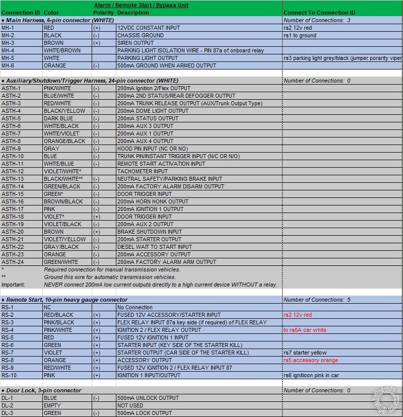
Your Viper 5706V has a 10 Pin heavy gauge wire harness that can support all but one of the the
vehicle ignition wires. Pin out below :
Remote Start, 10-pin heavy gauge connector
1 NC No Connection
2 RED/BLACK (+) FUSED 12V ACCESSORY/STARTER INPUT
3 PINK/BLACK (+) FLEX RELAY INPUT 87A key side (if required) of FLEX RELAY
4 PINK/WHITE (+) IGNITION 2 / FLEX RELAY OUTPUT
5 RED (+) FUSED 12V IGNITION 1 INPUT
6 GREEN (+) STARTER INPUT (KEY SIDE OF THE STARTER KILL)
7 VIOLET (+) STARTER OUTPUT (CAR SIDE OF THE STARTER KILL)
8 ORANGE (+) ACCESSORY OUTPUT
9 RED/WHITE (+) FUSED 12V IGNITION 2 / FLEX RELAY INPUT 87
10 PINK (+) IGNITION 1 INPUT/OUTPUT
You will need to use a relay to power the Brown Accessory2 vehicle ignition wire. You can use the Vipers thin Orange ACC (-) output to control the extra 30/40 Amp SPDT relay.
Below is the info on the clutch by-pass wire. This will require another 30/40 Amp SPDT relay controlled by the Vipers Blue Status Output or Purple (-) Starter Output wire.
Clutch Pedal DK GREEN (+) CLUTCH PEDAL SWITCH
Clutch Pedal dk. green (+) clutch switch, black 6 pin plug, pin D
The Fortin EVO-ALL install diagram does not show all the required connections for a manual transmission install. Remember that you must run in Tach Mode to allow use of the Vipers MTS Mode. Also the Vipers Neutral Safety Input wire must be connected to the trucks Parking Brake wire. Test to see if the trucks rear doors are monitored by the alarm. You might have to manually connect to the rear doors.
Parking Brake lt. blue (-) BCM under driver dash, lt. blue plug, pin A7
Additionally, the EVO-ALL must be flashed with the latest firmware ( Ver 70.18 ). You can set the Viper to a fixed 15 second "Wait To Start" delay for the diesel engine.
-------------
Soldering is fun!
Posted By: gtitonta
Date Posted: March 29, 2022 at 9:50 PM
thank you very much kreg357. I will fix my wiring scheme tomorrow, and post again.
Is it possible for you to take a look my diagram again sometime tomorrow night ?
appreciate it.
Posted By: gtitonta
Date Posted: March 30, 2022 at 6:58 AM
I updated my wiring diagram excel sheet. I would appreciate a lot if you take a look for me.
I have a few question also.
1. The first one is that accessory 2 wiring. What do I need accessory 2 wiring? what is for?
2. according to viper manual, I need hook ash-15 and asth-18 for MTS mode. However, fortin instruction shows that fortin module cover door status. Does this mean I do not need to hook these two wires?
Thanks a lot!

Posted By: kreg357
Date Posted: March 30, 2022 at 9:00 AM
Here is a link to a remote start install in a similar vehicle :
https://www.the12volt.com/installbay/forum_posts.asp?tid=133000
Of interest will be the two +12V constant wires in the ignition harness. You should split up you Viper power inputs between these two wires. Speaking of Viper +12V power inputs, there are four of them and they are all used for your install. Basically anything with a fuse gets power.
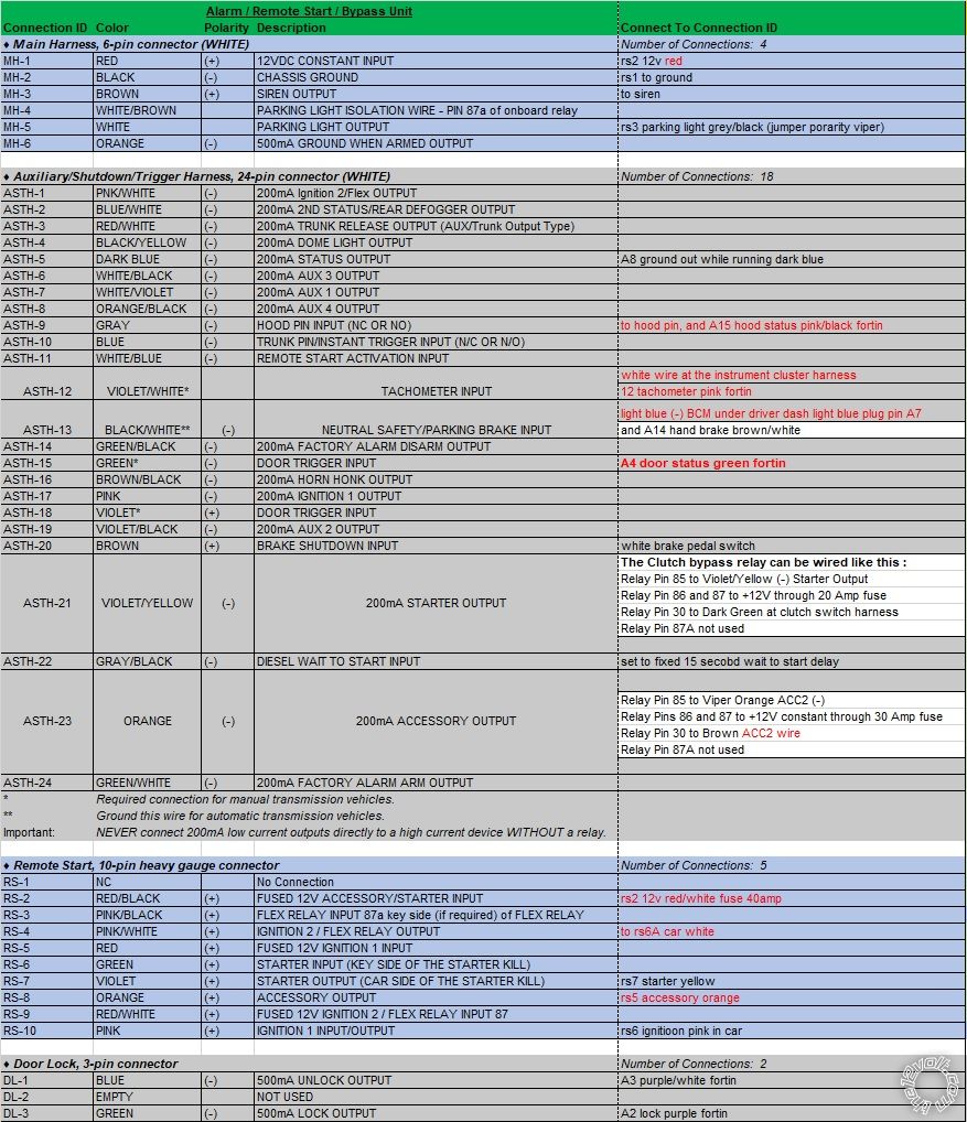
The EVO-ALL does not supply the vehicle Brake wire. Probably just an omission on your chart. ASTH-20 to White Brake wire at brake pedal switch.
The Brown ACC2 wire might not be necessary. Depending on the year it supplies power to various circuits. Some installers never use it. I always power it, just in case. The relay wiring goes like this :
Relay Pin 85 to Viper Orange ACC2 (-)
Relay Pins 86 and 87 to +12V constant through 30 Amp fuse
Relay Pin 30 to Brown ACC2 wire
Relay Pin 87A not used
The Clutch bypass relay can be wired like this :
Relay Pin 85 to Violet/Yellow (-) Starter Output
Relay Pin 86 and 87 to +12V through 20 Amp fuse
Relay Pin 30 to Dark Green at clutch switch harness
Relay Pin 87A not used
As for the Door Pin Inputs, the EVO-ALL might supply those signals. If you have a 4 door truck, you should test using the Viper alarm to verify that any door will trigger the alarm. Some bypass modules will only supply the front door pin signals. If this is the case with the EVO-ALL, you will have to hard wire those signals into the Vipers (-) Door Pin Input wire. Remember to diode isolate using 1N4001 diodes.
Left Rear Door Trigger lt. blue/black (-) BCM under driver dash, rear, violet 16 pin plug, pin A3
Right Rear Door Trigger lt. green/black (-) BCM under driver dash, rear, violet 16 pin plug, pin A2
I usually hardwire the Tach signal input to the White wire at the instrument cluster harness. More reliable than some bypass modules Tach Signal output.
Remember that if you want to go D2D between the Viper and the EVO-ALL you must select Option F3 during EVO-ALL flash to support DEI's D2D protocol.
-------------
Soldering is fun!
Posted By: gtitonta
Date Posted: March 30, 2022 at 2:54 PM
thank you very much, Kreg357. I really don't know how I thank you!
I thank you very much sincerely!
Posted By: kreg357
Date Posted: March 30, 2022 at 5:45 PM
No worries, we're here to assist. Add to and finish your wire chart with those updates and post it for a final forum review. Pretty sure your truck will look the same as the photos in the Pictorial. It should help with identifying the needed wires.
Do you have the FlashLink4 cable to flash and set options on the EVO-ALL?
-------------
Soldering is fun!
Posted By: gtitonta
Date Posted: March 30, 2022 at 5:59 PM
hello again,
I flashed fortin bypass, and there was no d2d option now. So I flashed with w2w connection.
I added more wire connection in the excel file. I think that everything is correct, but could you double check my wiring?
Thanks again sicerely
Posted By: kreg357
Date Posted: March 30, 2022 at 7:08 PM
Looking good. :) Almost there. Some updates...
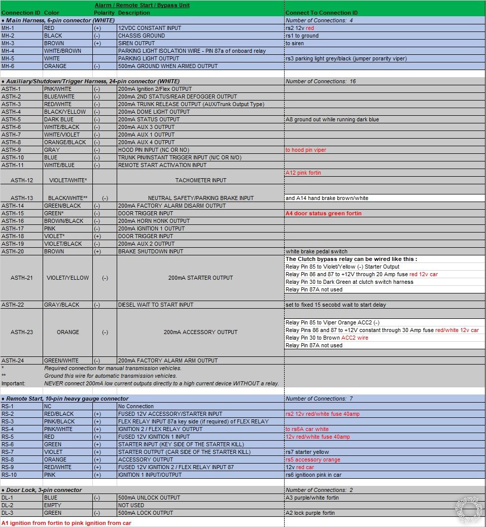
If your truck does not have a Factory installed hood pin, then the EVO-ALL will not be able to obtain and supply a Hood Pin output. The EVO-ALL Hodd Status signal at A15 is only an output. Therefore if you install the Viper kit supplied Hood Pin, only connect it to the Viper Hood Pin Input wire.
Same goes for the Tach Signal. If you go with the trucks Tach signal ( White wire at instrument cluster harness ) nothing will be connected to the EVO-ALL Tach Output wire ( not used ).
Ditto for the Parking Brake wire. However, if the EVO-ALL can supply that signal, you can just connect the Viper Neutral Safety Input wire to the EVO-All Handbrake Output wire and skip getting the signal at the BCM.
Still need to connect Viper RS-5 and RS-9 to +12V constant. Split between the Red and Red/White vehicle +12V power wires. The ACC2 relay power and the Clutch bypass relay power will come from these vehicle ignition harness power wires, too.
-------------
Soldering is fun!
Posted By: gtitonta
Date Posted: March 30, 2022 at 8:18 PM
thanks for comments and advice. Every time you gave me corrections, I learned more and more.
Thank you very for letting me learn these kind of wiring. I appreciate it.
So I think that this is the final version of the wiring for remote and alarm for my truck.
Hopefully I do not get any correction from you! thanks again. Appreciate it
Posted By: kreg357
Date Posted: March 30, 2022 at 9:10 PM
The Viper connections look good.
The EVO-ALL will have a few connections due to the W2W install mode.
You can connect the Plug B Red and Black directly to the Viper Red and Black MH-1 and MH-2.
The EVO-ALL A1 Yellow wire can go to the Viper thick Pink, which goes to the trucks thick Pink wire.
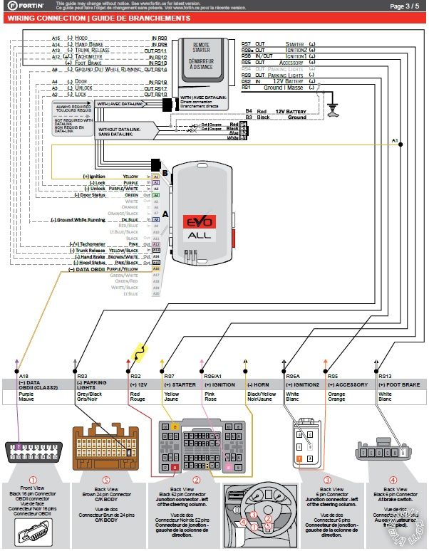
The only EVO-ALL connection to the truck is the ODB-2 J1850 Purple wire connection.
This is shown on the EVO-ALL wiring diagram.
You should do a Viper Tach Learn procedure after the EVO-ALL is programmed to the truck. Then test the Viper alarm system to ensure in monitors all the doors and the hood pin. The final test would be successfully getting into Reservation Mode, and then a R/S.
-------------
Soldering is fun!
Posted By: gtitonta
Date Posted: March 31, 2022 at 4:08 AM
Thank you so much, Kreg357! I am going to install viper and fortin on this weekend.
|