2004 Cadillac Escalade, Accessory 2 Wire
Printed From: the12volt.com
Forum Name: Car Security and Convenience
Forum Discription: Car Alarms, Keyless Entries, Remote Starters, Immobilizer Bypasses, Sensors, Door Locks, Window Modules, Heated Mirrors, Heated Seats, etc.
URL: https://www.the12volt.com/installbay/forum_posts.asp?tid=147307
Printed Date: May 15, 2026 at 8:37 AM
Topic: 2004 Cadillac Escalade, Accessory 2 Wire
Posted By: merkum901
Subject: 2004 Cadillac Escalade, Accessory 2 Wire
Date Posted: April 01, 2022 at 3:36 PM
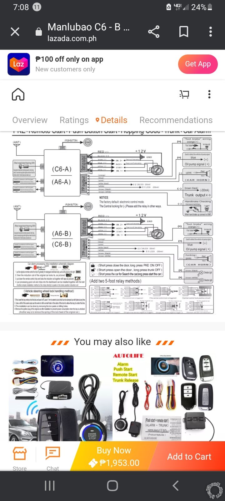
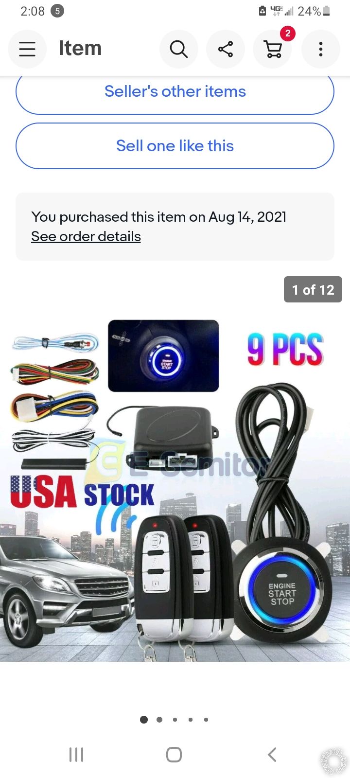
Hey guys I'm installing push and remote start on my 2004 Escalade and I wanted to know does the acc 2 wire need to be connected. I have one of the ebay pke systems and it doesn't say anything about connecting the wire but I just wanted to be sure because I was told to wire it with acc 1 wire. Also on my GMDLBP module what does the brown ground wire connect to. I'm guessing it doesn't connect to chassis ground like the black wire. Thanks in advance. I'm very impressed by the knowledge you guys possess here.
-------------
04 Escalamb
Replies:
Posted By: kreg357
Date Posted: April 03, 2022 at 9:04 AM
Can you supply any information about the EBay PKE and R/S system?
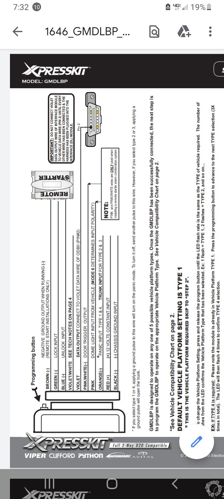
I'm not sure exactly what circuits are powered by the Brown ACC2 wire in your Escalade. As a basic GM platform, the Brown ACC2 wire handles different circuit over the years. Some installers never power it. I always add the extra relay and power it. Try to find a source for vehicle wiring diagrams. The important thing is to ensure that the White IGN2 wire gets power during a R/S.
As for the bypass modules Brown wire, it needs to see a signal called (-) Status Output or (-) GWR ( Ground When Running ). Some R/S controllers used to call it (-) 3rd Ignition. Not sure what capabilities your EBay system has, hence the request for more info.
-------------
Soldering is fun!
Posted By: Ween
Date Posted: April 03, 2022 at 4:32 PM
Ignition Switch schematic starting on page 108...https://www.gmupfitter.com/wp-content/uploads/2021/05/2005_LD_CKFullSizeElectrical.pdf
Posted By: merkum901
Date Posted: April 07, 2022 at 7:28 AM
 ------------- 04 Escalamb
Posted By: merkum901
Date Posted: April 07, 2022 at 7:30 AM
 ------------- 04 Escalamb
Posted By: merkum901
Date Posted: April 07, 2022 at 7:33 AM
 ------------- 04 Escalamb
Posted By: kreg357
Date Posted: April 07, 2022 at 2:23 PM
Gotta love these "off-shore" items. Good news and bad news... A quick review of the diagram.
First the good news : The system can support both vehicle Ignition wires. If you don't power the White IGN2 wire during a R/S, you will cause problems.
With a couple of relays, you could add support for the Brown ACC2 wire. May not be necessary but...
Plenty of bad news : It appears that the system monitors the Oil Pressure to determine if the engine is started. This is a poor substitute for using a quality Tach Signal and fraught with problems. Typically inexpensive, low quality systems employ the oil pressure method.
I can't find a signal called GWR or one that could be used as GWR. The instructions seem to talk about placing the transponder chip in close proximity to the steering column pick-up antenna. However, your vehicle uses Passlock2 and does not have a transponder chip in the key. While you could do a hard permanent Passlock2 bypass instead of using the GMDLBP module, it would further compromise vehicle security. As part of the install you actually place a cut key into the ignition switch and leave it at ACC. It is possible to create a (-) Ignition signal using two relays that might work as the GMDLBP Brown GWR input. ( GWR usually precedes IGN1 by one second ). There is only one +12V power supply wire for the system. Not sure if this input wire is even fused. However, the typical R/S system used on these trucks has two +12V input wires each fused at 30 Amps. I am not sure what the normal current draw is to R/S and run this vehicle but I do know all the ignition wires are 12 gauge with the exception of the White IGN2 wire ( 14 gauge ). The vehicles' +12V constant wires going to the ignition switch are rated at 30 Amp ( Red ) and 40 Amp ( Red/White ). Of course with some more external relays to power IGN2 and ACC1 & ACC2, you could safely power the ignition wires with out overheating the PKE / R/S system or the lone +12V input wire.
Good luck with your install.
-------------
Soldering is fun!
Posted By: hav007-roco
Date Posted: April 13, 2022 at 1:41 AM
I would try to hook up second second accessory, usually for heat. GM likes to do crazy things when sequence is not seen. Definitely make sure second ignition is hooked up
-------------
Rocky Verma
Posted By: merkum901
Date Posted: April 26, 2022 at 3:02 AM
Can you please let me know what connections to make including relays if needed just wire the push button start only. Thanks for the replies guys.
-------------
04 Escalamb
|