Compustar CSX-4900S, 2003 Ford F-250 Diesel
Printed From: the12volt.com
Forum Name: Car Security and Convenience
Forum Discription: Car Alarms, Keyless Entries, Remote Starters, Immobilizer Bypasses, Sensors, Door Locks, Window Modules, Heated Mirrors, Heated Seats, etc.
URL: https://www.the12volt.com/installbay/forum_posts.asp?tid=147359
Printed Date: April 22, 2026 at 9:04 PM
Topic: Compustar CSX-4900S, 2003 Ford F-250 Diesel
Posted By: l-ight
Subject: Compustar CSX-4900S, 2003 Ford F-250 Diesel
Date Posted: May 17, 2022 at 7:14 AM
Hello,
I have researched a good bit and still am coming up short on some wires I am trying to locate. I have a compustar CSX-4900S kit with drone. My truck is a 2003 with keyless entry, I believe as I have the key fob. The diagram from Compustar is as follows:
Compustar Ignition Harness 8 Pin Harness
(+) 12v Constant - Red - Tied into (+)Yellow wire on Ignition Switch. (Is it ok to tie both 12v Constants into one and then tie it to the Yellow wire on Ignition Switch?)
(+) 12v Light - Green/White - Not sure where this goes?
(+) 12v Constant - Red/White - Tied into (+)Yellow wire on Ignition Switch. (Is it ok to tie both 12v Constants into one and then tie it to the Yellow wire on Ignition Switch?)
(+) 12v Accessory - Tied into (+)Gray/Yellow wire on Ignition Switch.
(+) Selectable by jumper (Default Ignition) - Blue - Don't know where this goes?
(+) 12v Starter - Yellow - Tied into (+)Dark Green wire on Ignition Switch.
(+) 12v Ignition (output/Input) - Green - Tied into (+)White/Yellow wire on Ignition Switch. (Is it possible I may have hooked up the wrong wire and that I need to hook up the R/S Blue wire to the White/Yellow wire on Ignition Switch?)
GND - Black
Compustar 12 Pin Harness
(-) Parking Light Output (POC#1) - Green/White - Tied into (+)Brown wire on Parking Light Switch. (Is tying the R/S wire into the positive Brown wire ok?)
(-) Lock Output (POC #2) - Blue/Green - Tied into (-)White/Red wire at Kicker Panel (Assuming my truck is Keyless Entry since it has a Keyfob).
(-) Unlock Output (POC #3) - Blue - Tied into (-)Black/White wire at Kicker Panel (Assuming my truck is Keyless Entry since it has a Keyfob).
(-) Status Output (POC #4) - Black - Don't know where this goes?
(-) Rearm Output (POC #5) - Orange - Don't know where this goes?
(-) Disarm Output (POC #6) - Orange/White - Don't know where this goes?
(-) Horn Output (POC #7) - White - Tied into Dark Blue wire at Steering Column Harness.
(-) Hood Pin Input - Gray/Black - Tied into a firewall spare wire into engine bay.
(+) Foot Brake Input - Light Blue/White - Tied into (+)Light Green wire on Brake Switch.
(-) Trigger Starter Input - Red/White - Don't know where this goes?
(+) Trigger Starter Input - Red - Don't know where this goes?
Tach/Alt Sensing Input - Yellow/Black - Either I tie this into Green/White wire on 5 pin connector behind Parking Brake or use spare wire and tie into Ignition Coil in engine bay.
I went by a few guides from here https://www.the12volt.com/installbay/forum_posts.asp?tid=101287 and on other sites such as https://www.bulldogsecurity.com/bdnew...gdiagrams.aspx
I guess I am not understanding Compustar's lingo with some wire locations. For example rearm/disarm and trigger starter (-) and (+).
Replies:
Posted By: kreg357
Date Posted: May 17, 2022 at 8:56 PM
Here is a Pictorial on your truck. Only difference is that yours is a diesel and some of the ignition wires are different colors.
https://www.the12volt.com/installbay/forum_posts.asp?tid=133810
There are two Ignition and two Accessory type wires at the ignition switch harness. The 4900-S module can be programmed to directly support all the needed ignition wires except ACC2.
On a diesel truck the IGN1 wire is White/Yellow. Here is how the ignition wires probably are :
Ignition #1 White/Yellow IGNITION SWITCH HARNESS
Ignition #2 Black/Green IGNITION SWITCH HARNESS
Accessory #1 Gray/Yellow IGNITION SWITCH HARNESS
Accessary #2 RED/BLACK IGNITION SWITCH HARNESS
Starter #1 DARK GREEN IGNITION SWITCH HARNESS
The truck has a Brown (+) Parking Light wire. Use the thick Green/White (+) Parking Light wire at CN1-2 for this, not the thin Green/White (-) Parking Light wire.
Split the +12V constant power input wires between the available +12V constant supply wires at the ignition switch.
If your truck does not have an engine immobilizer system (PATS), then you don't need a bypass module or the Black (-) Status Output wire.
If your truck does not have a Factory Alarm system, then you don't need the Arm and Disarm wires.
You won't be using either Trigger Start wire.
Finding a good Tach Signal source can be tricky. You don't have Coil Packs to use. Here is some more info
On 7.3L Diesel Vehicles - The Tach Wire Is GREEN In A 42 Pin Plug Under The Clamp On The Engine Side Of The Air Intake Duct.
On 6.0 Turbo Diesel Vehicles-The Tach Wire Is ORANGE In a BLACK 46 Pin Conn At The PCM Located On Driver Fender Wall. (Pin 43 Bottom Row Of Middle Conn)
Hopefully your truck has an Auto Trans because the 4900-s is not for use with a Manual Transmission.
-------------
Soldering is fun!
Posted By: l-ight
Date Posted: May 17, 2022 at 11:21 PM
Thanks for the reply. So I just wrapped up the install. Ran into some speed bumps but got through it.
I do have a factory alarm but I never wired up the arm/disarm from the R/S. I wasn't sure what to do. I did not test my alarm as it is late now. I'll definitely check that out, but if the alarm doesn't work no biggie.
I did find the white/green tach wire that was mentioned in several threads. Though when I plugged my dmm into it it showed 12v (it's been mentioned it should be from 1v to 6v) while truck was running which was strange. Before splicing it the truck would start and run for a few seconds then die. Then start again 2 more times. Once I spliced into that white/green tach wire it worked.
I left many wires that I had no idea what they were for. Hopefully I won't need them.
Posted By: l-ight
Date Posted: May 17, 2022 at 11:37 PM
Quoting myself with the wires I did use. They will be in bold.
l-ight wrote:
Compustar Ignition Harness 8 Pin Harness
(+) 12v Constant - Red - Tied into (+)YellowX1 wire on Ignition Switch.
(+) 12v Light - Green/White - Tied into Brown parking wire.
(+) 12v Constant - Red/White - Tied into (+)YellowX2 wire on Ignition Switch.
(+) 12v Accessory - Tied into (+)Gray/Yellow wire on Ignition Switch.
(+) Selectable by jumper (Default Ignition) - Blue - Don't know where this goes?
(+) 12v Starter - Yellow - Tied into (+)Dark Green wire on Ignition Switch.
(+) 12v Ignition (output/Input) - Green - Tied into (+)White/Yellow wire on Ignition Switch.
GND - Black
Compustar 12 Pin Harness
(-) Parking Light Output (POC#1) - Green/White - Tied into Light Blue/Black wire on driver kicker panel. (This may be a wire I don't even need. Any help here?)
(-) Lock Output (POC #2) - Blue/Green - Tied into (-)White/Red wire at Kicker Panel.
(-) Unlock Output (POC #3) - Blue - Tied into (-)Black/White wire at Kicker Panel.
(-) Status Output (POC #4) - Black - Don't know where this goes?
(-) Rearm Output (POC #5) - Orange - Don't know where this goes?
(-) Disarm Output (POC #6) - Orange/White - Don't know where this goes?
(-) Horn Output (POC #7) - White - Tied into Dark Blue wire at Steering Column Harness.
(-) Hood Pin Input - Gray/Black - Tied into a firewall spare wire into engine bay.
(+) Foot Brake Input - Light Blue/White - Tied into (+)Light Green wire on Brake Switch.
(-) Trigger Starter Input - Red/White - Don't know where this goes?
(+) Trigger Starter Input - Red - Don't know where this goes?
Tach/Alt Sensing Input - Yellow/Black - Tied into green/white wire behind parking brake.
Posted By: kreg357
Date Posted: May 18, 2022 at 5:14 AM
(Default Ignition) - Blue - Don't know where this goes?
I would leave the programming at IGN2 and connect to the thick Black/Green at the ignition switch harness.
Double check that the heater controls/fan works while remote started.
If the truck has the Factory Alarm, it will arm and disarm using the Compustar and the it's Lock and Unlock connections. If the truck is locked and armed & the alarm is triggered when you remote start the engine, set the Compustar for "Unlock before and Lock after" remote start. See Menu 1, Feature 1 set to Option 2.
Running in Tach Mode is important. Did you set Menu 2-04 to Option 2 ( Tach Mode ) and do a Tach Learn. Additionally, with a Diesel, you should set a Diesel Wait To Start Delay. That's Menu 2-03.(+) Selectable by jumper
-------------
Soldering is fun!
Posted By: l-ight
Date Posted: May 18, 2022 at 5:48 AM
I left the Blue wire unconnected and it seems to work just fine. I have not tested to make sure the heater/control fans work yet with R/S. I will do that later this morning. As mentioned I do have the factory alarm. Now since I do should I hook up the arm/disarm and if so where do I tie into the truck here? I did not set it to tach learn, but I can go ahead and set that as well later this morning. I did change the delay start for my glow plugs at 7 seconds. I live in Houston so that is plenty of time for the plugs to warm in summer and winter.
Posted By: kreg357
Date Posted: May 18, 2022 at 7:29 AM
The Compustar Arm and Disarm wires are used to control the Factory Alarm IF necessary. I have not done a 2003 F250/F350/Superduty diesel with a Factory Alarm but if the Compustar Lock and Unlock commands/connections control the Factory Alarm, there should be no need to connect the Arm and Disarm wires. If you did connect the Disarm wire to the same wire the Unlock wire is connected to, during a R/S the Disarm pulse would turn off the Factory Alarm and also unlock the door(s). Then you would have to find a way to re-Lock the doors after the engine is running for vehicle security. That is what the "Unlock before, Lock after" Compustar programming option is for. Check to see if the Factory Alarm goes off with a R/S. If yes, then turn on "Unlock before/Lock after" function. If no alarm with a R/S, you're done.
None of the wire listings I have show an individual wire for Factory Alarm control. They just say "Arms with Lock and Disarms with Unlock".
-------------
Soldering is fun!
Posted By: l-ight
Date Posted: May 18, 2022 at 9:08 AM
Funny thing now is it won't start now from remote or drone app. I bet I must have moved/pinched a wire that I tapped into when I buckled everything back together. It was working just fine when it was all out.
Update. I wire did come loose. All fixed now.
Posted By: kreg357
Date Posted: May 18, 2022 at 10:49 AM
I glad it's all working but... a loose wire?
I realize that I'm a paid installer that can't stay in business if I get any "come-backs" but you are running a heavy diesel truck with a very stiff suspension. This is a vehicle that should have all connections properly soldered and well insulated. I've seen these systems still working after a decade and all the customer needs is a new battery for the remote or a replacement remote. Just saying...
-------------
Soldering is fun!
Posted By: l-ight
Date Posted: May 18, 2022 at 11:33 AM
I used T-taps and one was pulled off when bolting up the fuse panel. I am just a self installer and my truck does not see any wear and tear. Just used as my personal vehicle. Was given to me by Dad in immaculate condition. So I misinformed you with a "loose" wire when really the R/S wire was pulled off the T-tap.
Posted By: kreg357
Date Posted: May 18, 2022 at 1:24 PM
No worries. With a DIY install on a personal vehicle, you accept those minor issues. No wires were cut so the worst that happens is the R/S is out of commission, but the vehicle still works normally with a key.
T-Taps are another no-no for me. They can damage the vehicle wire, have reduced current transfer capabilities (thick ignition wires) and can't handle two different gauge wires. With age they can lose tension, etc.
Enjoy the new and improved truck!
-------------
Soldering is fun!
Posted By: l-ight
Date Posted: May 18, 2022 at 1:43 PM
What would be a good alternative besides cutting/splicing/soldering?
Upon further research looks like I should have gotten some Posi-Taps. Those look great and secure.
Posted By: kreg357
Date Posted: May 18, 2022 at 3:46 PM
Good question. I solder all my connections. Soldering isn't all that difficult and the cost of tools isn't very much. A decent soldering iron (Hakko FX600) can be had for $60. Kester 245 core solder is $10 for a small tube.
I do occasionally use Posi-Tap connectors to make a temporary connection on CAN wires during bypass module programming. These CAN wires are typically 20 or 22 gauge. I have heard that the Posi-Taps work well for permanent connections. They aren't cheap and they are gauge range specific.
There is another way to make a decent connection in a favorable environment. It's called the "Poke and Twist" method. Description below.
This would be for your thick gauge vehicle ignition wires (but will work with thinner gauge wires). Strip about 3/4" inch insulation from the vehicles ignition wire in an accessible area. Strip about 1 1/4" insulation from the end of the R/S ignition wire and put a tight twist to the exposed strands of wire. Using a pointed plastic tool, separate the vehicles ignition wire braids into two equal parts creating a gap you can poke the R/S ignition wire through. Then tightly squeeze the separated wire back together and then wrap the R/S wire tightly around the exposed vehicle wire, both sides. Align the R/S wire with the vehicle wire and apply Scotch Super 33+ insulation tape. Use tie wraps to secure the R/S wire to the vehicle wire over the insulation tape and the other end of the insulated area. Some diagrams from Bulldog Security below :
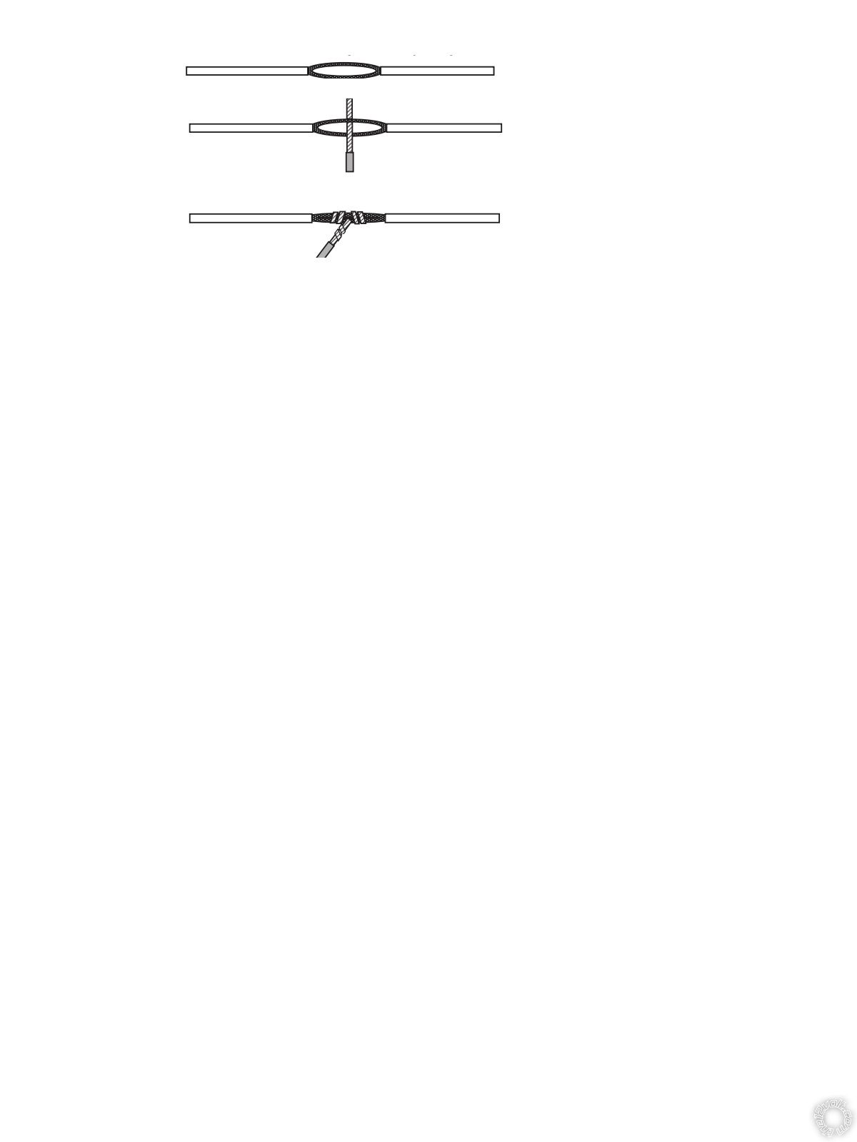 ------------- Soldering is fun!
Posted By: l-ight
Date Posted: May 19, 2022 at 6:14 AM
Thank you for helping me, btw. I hope this can help others in the future.
|