Hello all,
I have done some research trying to find a solution to my problem on here as well as other forums but have had little luck finding anything relevant. I have a 2002 Silverado 2500HD with the duramax. I have installed my Firstech FT-DC3-LC using the low/high current harness and have it all soldered in. This r/s system is supposed to be able to use the oem factory key fob using three clicks of the lock button to start the vehicle. I have ran through the weblink menus several times and I think I have all of the settings set correctly but maybe not
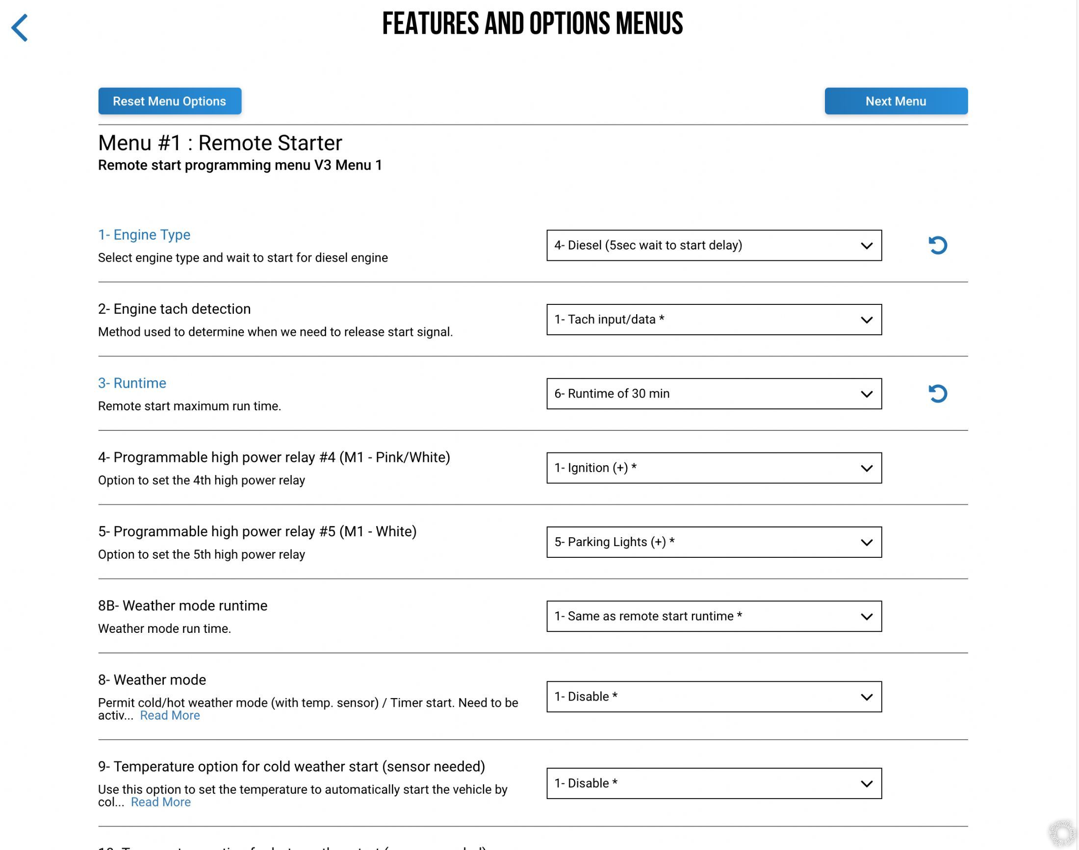
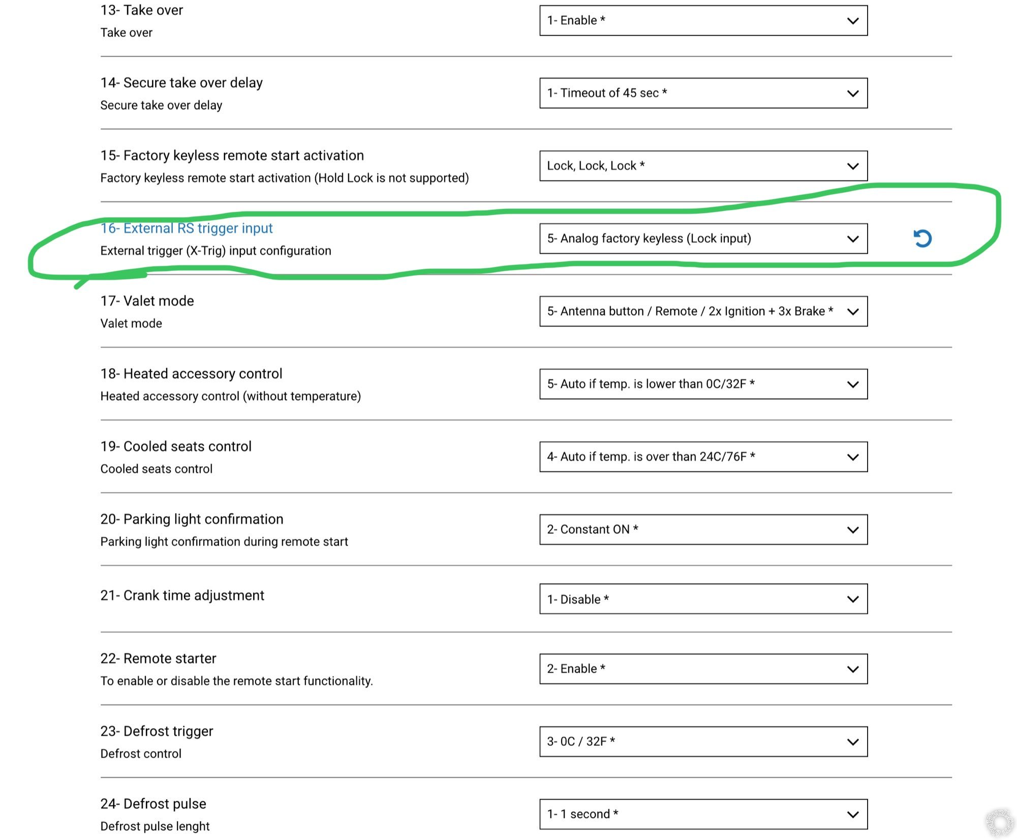
My issue is, the module does nothing once I do the lock presses on the fob. Will not wake up the truck and start. However, the programming sequence of the fob to the module found in Firstechs instruction manuals seems to have paired them successfully since I get the two chirps from the horn after one press of the lock on my fob. So I feel like it communicates, but when the door is closed and I do the 3 clicks - nothing happens. Here is a screenshot from the weblink settings I currently have.
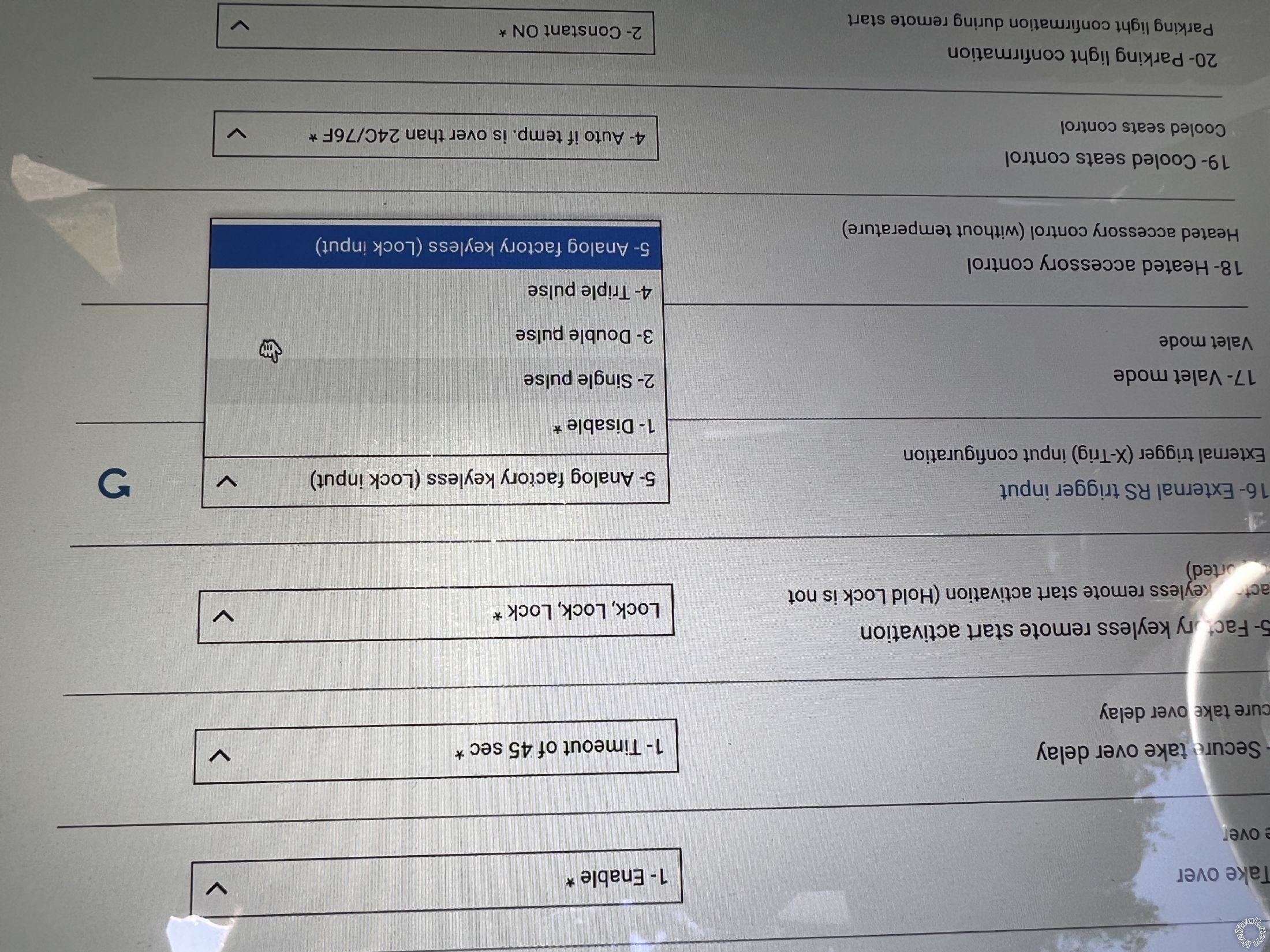
*I apologize for the upside down image
I have even played around with the pulse settings to see if it would make a difference. The purple wire on the obd2 for passlock bypass is wired of course. Just curious if anyone has any ideas on what the issue might could be. Thank you!
-------------
Clint
Have you tried the Default "Disabled" setting for 1-16? I don't believe you connect the (+) R/S Trigger Input wire to a door lock motor wire for that install.
-------------
Soldering is fun!
Yes. Thats how it was initially and then I found setting 1-16 and figured I would try it to see if it would make a difference. And youre correct about there not not needing to be an input connection. I think it is supposed to receive the command via remote pulse. I was thinking the menu was referring to this so I tried it. If that makes any sense
-------------
Clint
Analog usually means an old school signal and direct connection. With the J1850 wire connected, the DC3 senses/monitors the vehicles Data signal to lock the doors that is initiated by the Factory Remotes.
I use iDataStart modules and with their wiring, there is no wire going to the vehicles Lock motor wire and they can do a R/S with 3 locks in a row from the Factory Remote.
-------------
Soldering is fun!
Okay I understand. So change that back to disable? I soldered the orange wire from the M2 harness to the purple on the obd2. Is it okay solder that connection? Also, only the acc1 wire (orange), and only one of the 12v constant wires are connected (sold red, not red/white stripe). Is that okay? Can you explain all of the programming sequences I must go through? I may have missed one causing this, but maybe I didnt. I have found the idatalink manuals to be all over the place.
-------------
Clint
Yes, I would set that feature selection back to Disable.
I might have an older DC3 install guide, but the Orange J1850 wire is on plug M4, not M2. Either way, soldered is good.
Considering the current draw of the ignition wires on that truck, I would split the +12V input load between the trucks Red and Red/White 12V supply wires. Connect one to each of the DC3's two thick Red wires.
Perhaps you could list your DC3 to ignition wire connections. That would help.
If you have remotes that came with the DC3 and they are paired, can you get a R/S with them? Did you make the other DC3 connections to the Parking Lights, Tach, Brake, etc?
As for DC3 module programming, after firmware flash the Defaults are a good starting point. Often times, they will automatically make any required changes for you.
-------------
Soldering is fun!
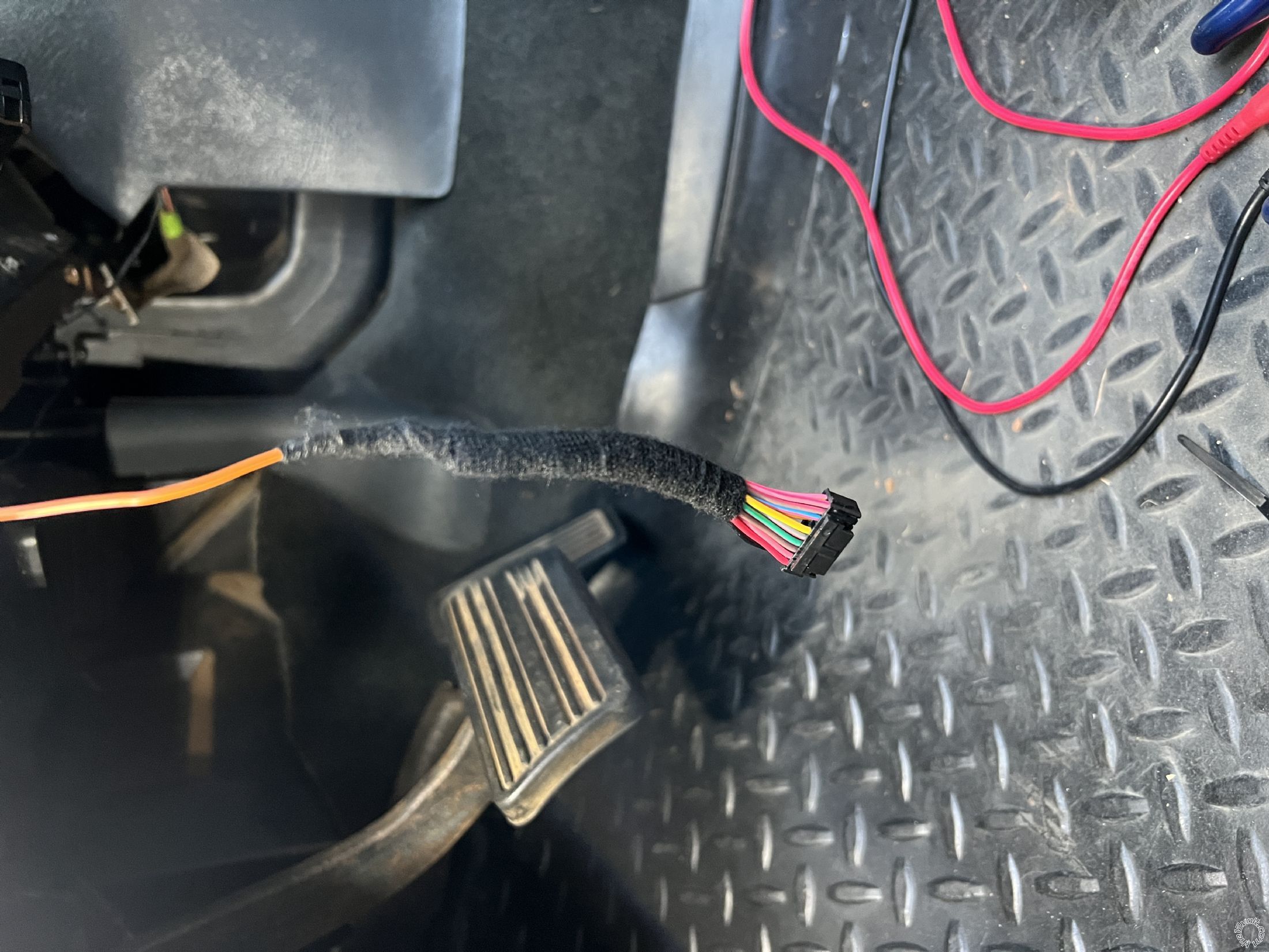
So a little back story is, last week when I was installing this, I was following your old pictorial on the 99-02 R/S install using an Avital I think it was? I figured out that the yellow starter wire for my diesel truck is different than that of the gas vehicle you did that install on. Mine uses a small gauge yellow wire coming from the ignition switch over to the back of the fuse block located on the left side of the dash.
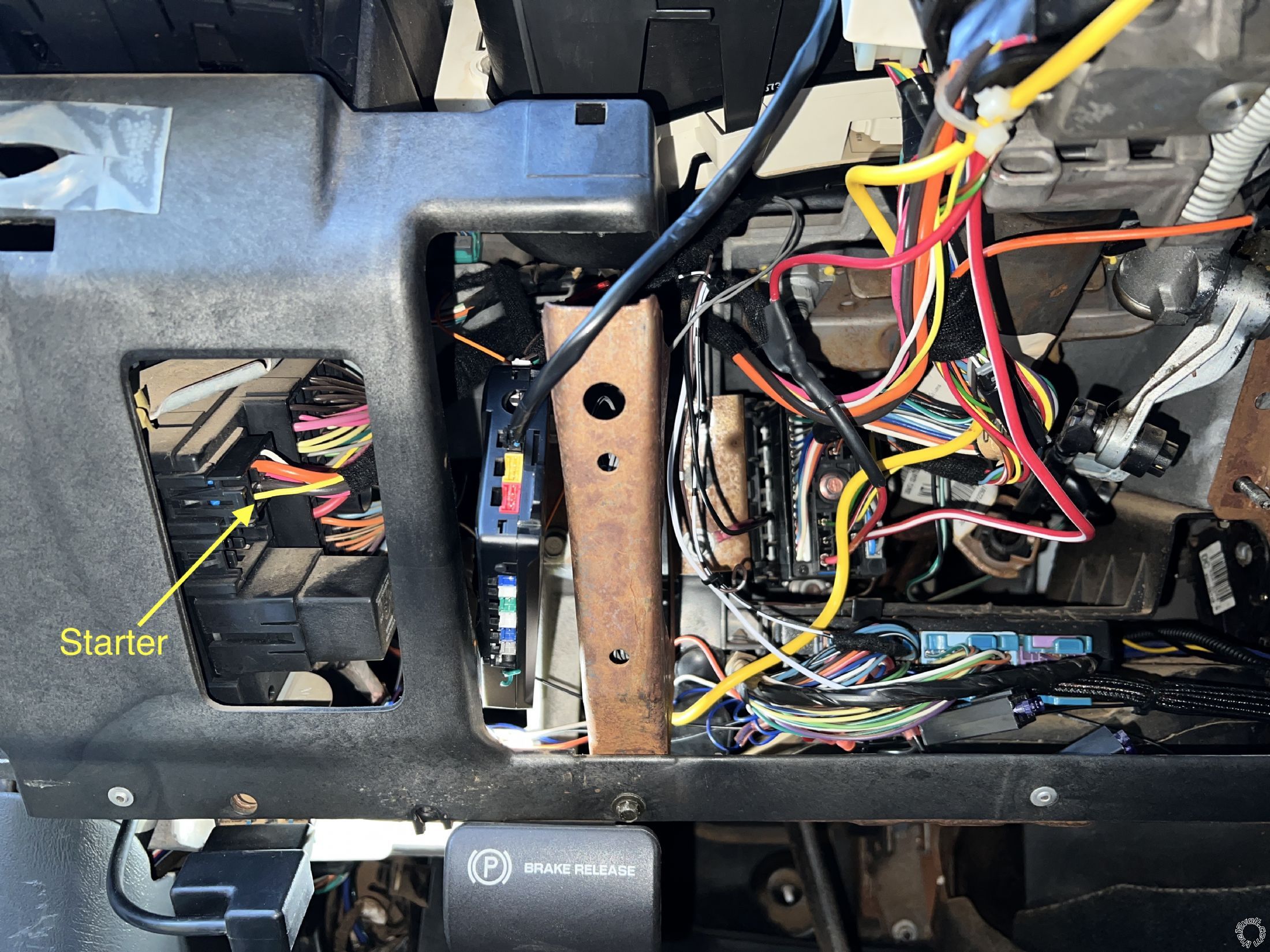
I'm guessing it powers a relay that then sends power to the starter. Not a single FB page or forum online showed which wire on a 2002 diesel was the starter wire, nor the install guide from Firstech. This is not your fault of course, I just figured it would have been more common than it is I guess. Rant over lol.
Yes, my J1820 orange wire going to the purple wire on the OBDII is in fact from the M4 plug. My apologies, I was getting the order of the connectors mixed up.
From the DC3 to truck I have the current connections,
M1 Connector:
Red (constant) to Red (constant) (may end up tying in the Red with white stripe)
Pink (IGN1) to Pink (IGN1)
Pink/white (IGN2) to White (IGN2)
Orange (ACC1) to Orange (ACC1)
Purple (Starter) to Yellow (small awg Starter)
White (Parking lights) to Brown (on light blue plug on BCM)
Black (Ground) to Dash stud
M2 Connector:
White/Black with Black Dot (Horn) to Black (on brown plug on BCM)
M3 Connector:
Brown with Silver Dot (+ Brake Input) to White (brake switch above pedal)
Purple/White with Silver Dot (Tach Input) to White (on back of cluster)
Hood wire not currently wired, was planning to install switch after R/S was functioning.
M4 Connector:
Orange (J1820) to Purple (OBDII)
Let me know if this looks correct to you.
I bought my FT-DC3-LC without any remotes and planned to only use the factory key fob so I am unsure if another remote paired will work.
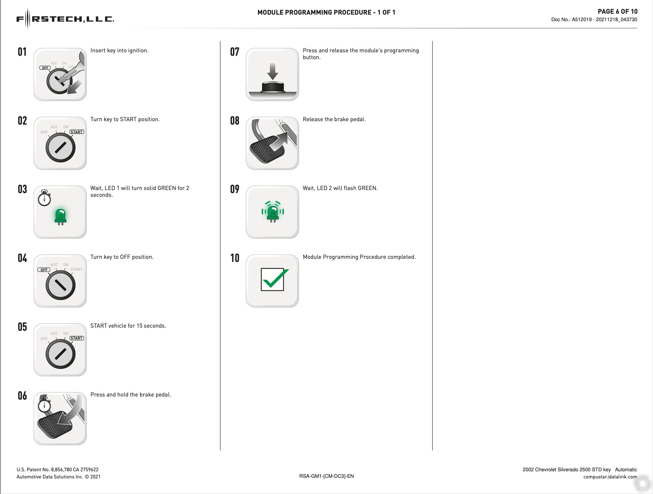
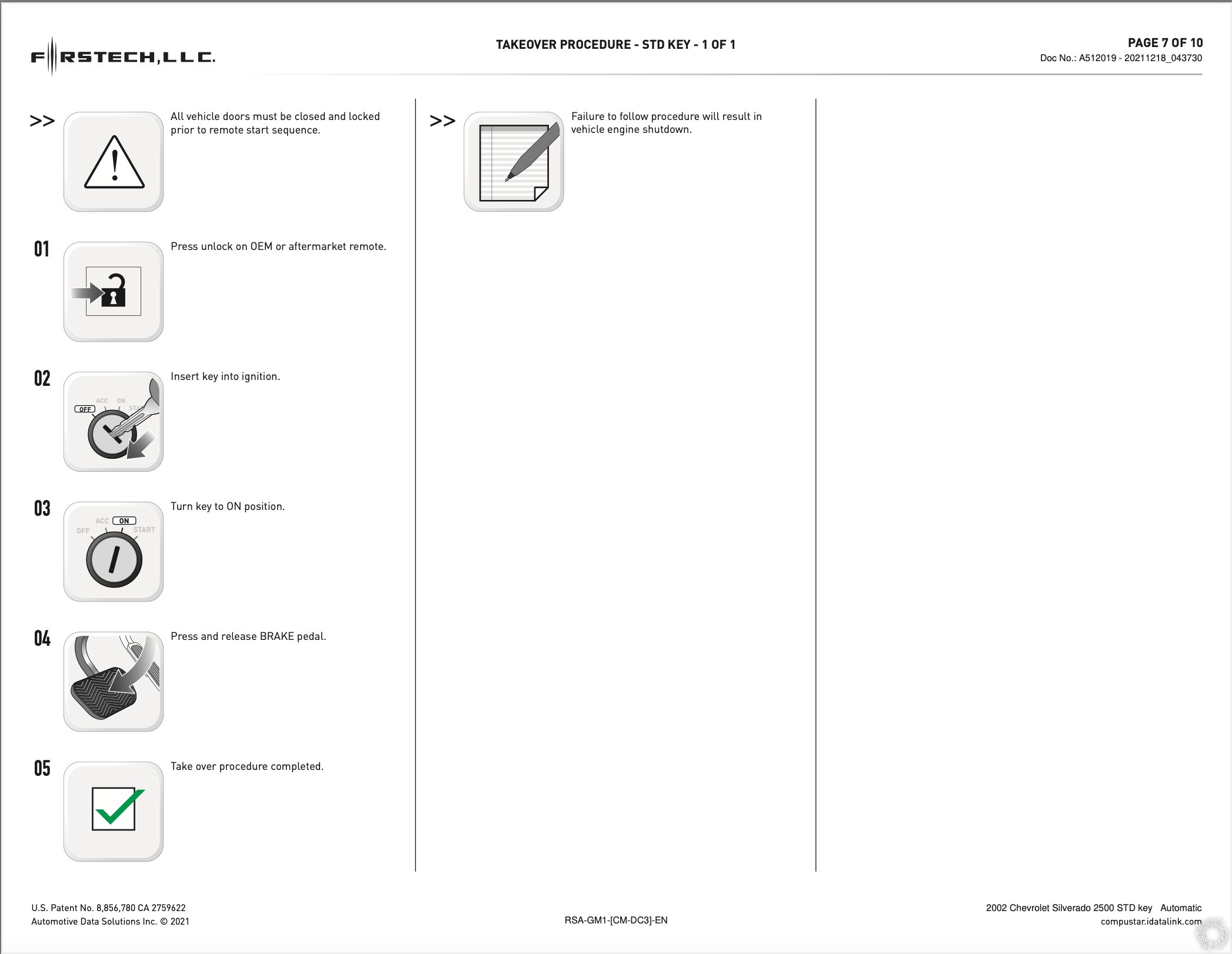
For the programming sequences, I am referring to these located here on pages 6 and 7.
I haven't done one for a while, but I seem to remember that the White IGN2 and the Yellow Starter wires were about the same gauge and thinner than the other ignition wires. It should be easy enough to test that Yellow Starter wire with a Digital Multi Meter to be sure. There are two Red +12V input wire on the DC3's M1 ignition harness each with a 30 Amp fuse. Both of these wires must be connected to a suitable +12V constant source wire. I would connect one Red to the vehicle Red and the other DC3 Red to the trucks Red/White wire. Splits the load and powers the DC3 properly.
As for DC3 module to vehicle programming, you must follow the steps listed. Verify a correct response via the LED when listed. Basically Steps 1 thru 3 allow the DC3 bypass module section to learn the Passlock2 signal and Steps 5 thru 9 get the DC3 to learn the J1850 signals and the Tach learn ( 2 blinks ). There are error codes for Tach Learn issues and problems during a R/S.
-------------
Soldering is fun!