Remote Start Brake Switch Relay
Printed From: the12volt.comForum Name: Car Security and Convenience
Forum Discription: Car Alarms, Keyless Entries, Remote Starters, Immobilizer Bypasses, Sensors, Door Locks, Window Modules, Heated Mirrors, Heated Seats, etc.
URL: https://www.the12volt.com/installbay/forum_posts.asp?tid=147521
Printed Date: May 15, 2026 at 5:34 AM
Topic: Remote Start Brake Switch Relay
Posted By: mohpro
Subject: Remote Start Brake Switch Relay
Date Posted: November 30, 2022 at 9:37 PM
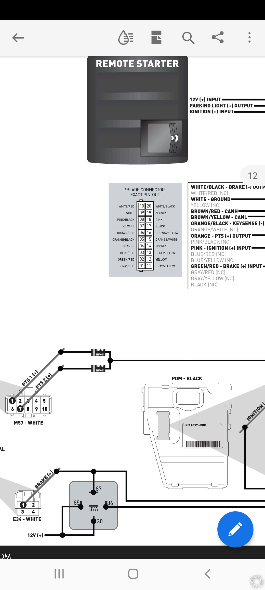
I am installing a remote start in my 2012 Hyundai Genesis Sedan, push to start. I am almost done. Lock, unlock, and trunk release buttons on the compustar remote work as they should. When you press the remote start button, the parking lights flash once, the ignition turns on, but it does not crank or start. I get a parking light flash pattern of 3 flashes, then a pause, then 5 flashes. This indicates a "foot brake on" error. I wired the relay for the brake switch just as it is in the diagram. 12V positive to pins 85 and 30, brake negative output from remote start module to pin 86, and both the brake positive input from the remote start module and brake 12V positive wire from the brake switch joined together at pin 87. Here are a couple pictures of the relay on the wiring diagram. And the two brake wires from the remote start module. According to this diagram, am i suppose to conmect the brake positive inpit wire from the remote start module directly to the 12v brale wire, then run a wire from the brake positive input wire to pin 87? Wouldnt that be the same as connecting the brake switch wire and brake positive input wires to pin 87 together?
Replies:
Posted By: mgoetz74
Date Posted: December 01, 2022 at 4:21 PM
yes, you go from the factory brake wire to 87 and also running green/red (bypass module) to the same 87. your kind making a V or 2 wire to one connection. and of course 86 goes to the white/black and 85 and 30 to constant 12 volts
-------------
33 years as a installer now just a retired old guy. Favorite thing to install/topic are remote starts/car alarms. Stop using test lights!!!
-------------
33 years as a installer now just a retired old guy. Favorite thing to install/topic are remote starts/car alarms. Stop using test lights!!!
Posted By: kreg357
Date Posted: December 01, 2022 at 4:53 PM
Follow the diagram.
How it works...
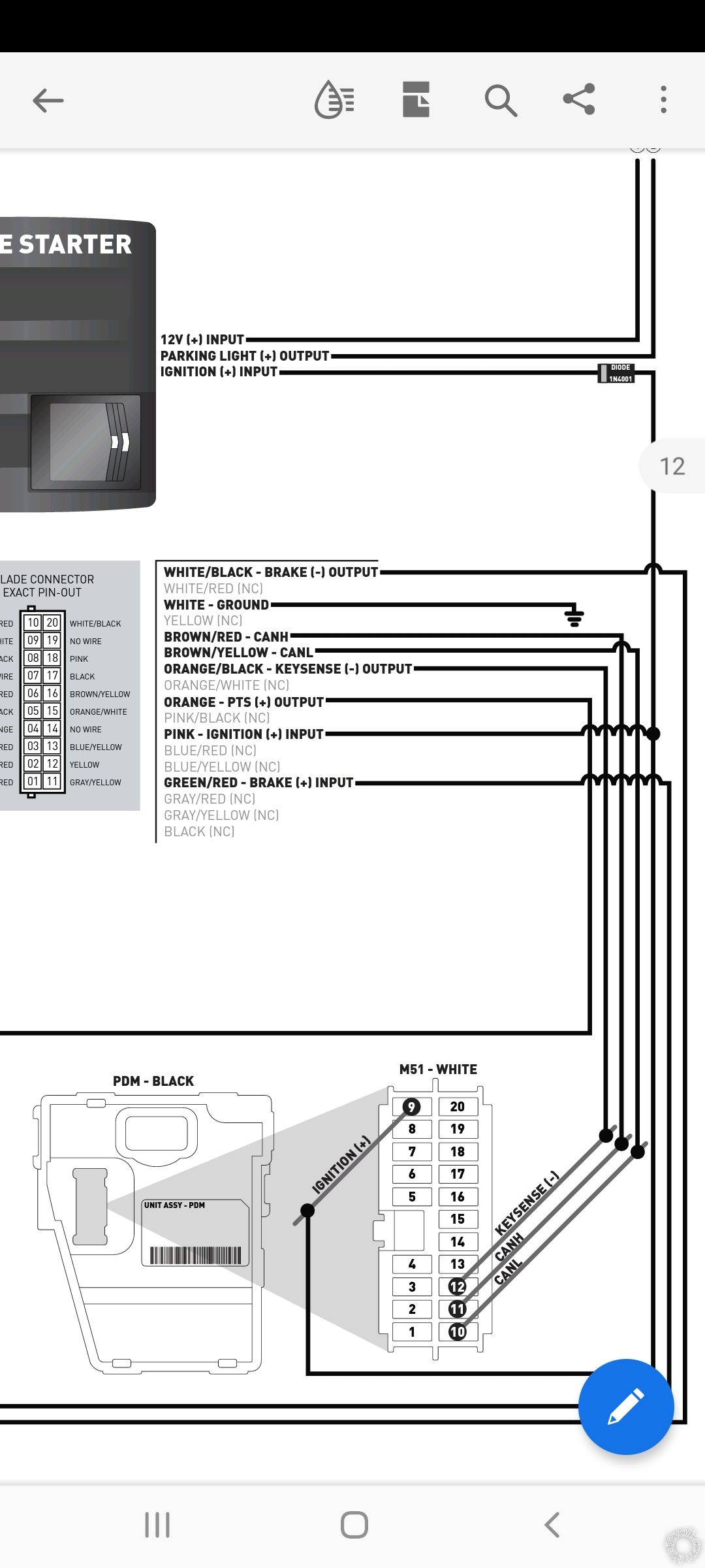
The vehicles Gray Brake (+) wire is monitored by the R/S system for a couple of reasons. It allows "take over" of the remote started vehicle ( unlock the vehicle, open the door, get in and step on the Brake pedal = take over). It is also used to prevent a R/S if the brake pedal is currently depressed. That same wire is used by the Compustar system to allow a R/S. When a R/S is imitated, the Compustar system first checks to ensure the Brake pedal is not depressed, then is uses its' internal relay to output a (-) signal ( White (-) input to White/Black output ) that in turn energizes the external relay that provides a (+) signal to the vehicles Brake wire to fool the car into thinking someone is stepping on the Brake pedal and allow a R/S.
"And the two brake wires from the remote start module. According to this diagram, am i suppose to connect the brake positive input wire from the remote start module directly to the 12v brake wire, then run a wire from the brake positive input wire to pin 87? Wouldn't that be the same as connecting the brake switch wire and brake positive input wires to pin 87 together?"
Not sure of the question above. Basically, follow the supplied diagram. You didn't mention the exact R/S model but I'm assuming a CM900-s unit. While the wiring guide is good, it assumes a generic R/S unit. With a CM900-s you would combine the two fused +12V Input wires into one wire and connect as shown. Not shown is the required Black Chassis Ground wire. There should be no need for other CM900-s wires like Lock, Unlock, Brake, Disarm, Hood and Tach. These are handled by the Blade cartridge and the CAN Bus wires. The Horn wire would be optional.
Make sure you use 1N4001 diodes that are oriented correctly.
-------------
Soldering is fun!
How it works...
The vehicles Gray Brake (+) wire is monitored by the R/S system for a couple of reasons. It allows "take over" of the remote started vehicle ( unlock the vehicle, open the door, get in and step on the Brake pedal = take over). It is also used to prevent a R/S if the brake pedal is currently depressed. That same wire is used by the Compustar system to allow a R/S. When a R/S is imitated, the Compustar system first checks to ensure the Brake pedal is not depressed, then is uses its' internal relay to output a (-) signal ( White (-) input to White/Black output ) that in turn energizes the external relay that provides a (+) signal to the vehicles Brake wire to fool the car into thinking someone is stepping on the Brake pedal and allow a R/S.
"And the two brake wires from the remote start module. According to this diagram, am i suppose to connect the brake positive input wire from the remote start module directly to the 12v brake wire, then run a wire from the brake positive input wire to pin 87? Wouldn't that be the same as connecting the brake switch wire and brake positive input wires to pin 87 together?"
Not sure of the question above. Basically, follow the supplied diagram. You didn't mention the exact R/S model but I'm assuming a CM900-s unit. While the wiring guide is good, it assumes a generic R/S unit. With a CM900-s you would combine the two fused +12V Input wires into one wire and connect as shown. Not shown is the required Black Chassis Ground wire. There should be no need for other CM900-s wires like Lock, Unlock, Brake, Disarm, Hood and Tach. These are handled by the Blade cartridge and the CAN Bus wires. The Horn wire would be optional.
Make sure you use 1N4001 diodes that are oriented correctly.
-------------
Soldering is fun!
Posted By: mohpro
Date Posted: December 06, 2022 at 9:12 PM
Long update but trying to include as many details as possible. Module is Firstech CMX with Blade AL bypass. Diodes are in the correct orientaion, and are 1N4001. I have made some progress with diagnosing this foot brake on error. I discovered that there is 9 volts flowing through the ground wire of the remote start module. This 9 volts of current is flowing through the ground wire of the remote start module even when the ground wire is disconnected from the grounding point. This main harness also includes two 12V+ wires, an ignition wire, and parking light wire.
Also, the same amount of voltage that is flowing through the ground wire is also flowing the brake+ input wire, even when it is disconnected from the brake wire switch. So to sum it up, the ground wire and brake + input wires from the remote start module both have 9 volts flowimg through them, even when disconnected. The brake + input wire should only have voltage flowing through it when the brake pedal is pressed down. The way this wire works is it connects to the vehicles brake switch wire that shows 12V when the brake pedal is pressed down. When the brake pedal is pressed down, the 12V is then sent through this brake + input wire, telling the remote start module that the foot brake is pressed down. This is what allows for the take over process when you get in your car after remote starting it, where you press on the brake and the remote start module shuts down and the engine keeps running as if you started it with the key, then you can put it in gear and drive. As a result of the brake + input wire always having voltage flowing through it, even when disconnected, it is communicating to the remote start module that the foot brake is on, creating this error. The voltage flowing through the brake + input wire even when disconnected, only happens when the main harness for the remote start, which includes the ground wire, is plugged into the remote start. When I unplug the main harness from the remote start module, which includes the ground wire, there is no longer voltage flowing through the brake + input wire. As soon as I plug in that main harness that includes the ground wire, there is voltage flowing through the brake + input wire again, as well as the ground wire, so the voltage running through the ground wire is transferring over to the connector that has the brake + input wire. So clearly my main focus should be determining how / why voltage is flowing through the ground wire, and seeing if it is something that I can fix. Also, there is 7 ohms of resistance in the ground wire.
What should be the next series of testing I do with my multimeter? Or, is it more than likely an internal fault of the remote start module? What are some of the possible causes of 9 volts flowing through the ground wire? I ordered a new remote start module (same model) which will be arriving tomorrow (12/7). Im going to see if the new module fixes it, then that would confirm the current remote start module has an internal fault.
Thanks in advance for any guidance and/or any additional testing I can do to narrow it down.
Posted By: mohpro
Date Posted: December 08, 2022 at 4:26 PM
Allright I am making more progress (at least I think I am). Last night I continued trying to figure out the problem. At this point I have reason to believe it is a wiring or diode issue with the PTS wire from the RS module that splits into two, and one wire connects to the white wire at terminal 7 of the PTS button connector, and the other wire connects to the orange / black wire at terminal 1 of the PTS button connector. Each one of the two remote start wires with a 1N4001 diode in line, with the cathode of the diodes facing in the direction of the PTS connector.
Now for the reasons I believe this is where the problem is. After reconnecting and disconnecting the lower dash panel that the PTS button is mounted in, multiple times (keep in mind while doing this, the harness for the PTS button is going to move.) At some point, after reconnecting the lower dash panel, and plugging the PTS button connector back in, I pressed the RS button on the remote. To my pleasant surprise, I did not get the foot brake on error, or any other error for that matter! Instead, what happened was the remote chirped back with the confirmation tone that the remote start was succesful! However, the car never actually started. What happened was it got to the point where the fuel pump turned on, and the brake relay energized, turning the brake lights on, then the confirmation chirps and led flashes happened on the remote indicating the remote start was succesful! Almost immediately after the sucessful RS confirmation feedback on the remote, the confirmation lights on the remote turned off, as if the remote start was shut down (keep in mind, even after this, I still did not get any error codes!) I repeated this process about 4 times in a row, with the same exact result all 4 times in a row! (No error codes, remote start confirmation chirps and LED flashes on remote, then immediate shut down, with no error codes following) Then after the 4th time I did this, for some reason I wiggled the PTS button harness, then went to go take a video on my phone to post here when I do the remote start to show what happens. Well, after wiggling the harness it went back to giving the foot brake on error. Im almost certain its one of the two PTS button wires, or one of the diodes came loose or went bad. I looked up the PTS button wiring diagram for this car. Pin 7 of the PTS connector is the wire that receives the brake light signal. Pin 1 of the PTS connector is the wire that receives the signal from pin 7 that the brake light signal has been received, then sends a signal to the starter relay, which then starts the car. Given these facts, I feel very strongly I am going to find the problem somewhere within the PTS wires, whether the problem is with one or both diodes or the wires themselves. I am going to get back to it tonight and provide an update. How does everyone else feel about this?
Now for the reasons I believe this is where the problem is. After reconnecting and disconnecting the lower dash panel that the PTS button is mounted in, multiple times (keep in mind while doing this, the harness for the PTS button is going to move.) At some point, after reconnecting the lower dash panel, and plugging the PTS button connector back in, I pressed the RS button on the remote. To my pleasant surprise, I did not get the foot brake on error, or any other error for that matter! Instead, what happened was the remote chirped back with the confirmation tone that the remote start was succesful! However, the car never actually started. What happened was it got to the point where the fuel pump turned on, and the brake relay energized, turning the brake lights on, then the confirmation chirps and led flashes happened on the remote indicating the remote start was succesful! Almost immediately after the sucessful RS confirmation feedback on the remote, the confirmation lights on the remote turned off, as if the remote start was shut down (keep in mind, even after this, I still did not get any error codes!) I repeated this process about 4 times in a row, with the same exact result all 4 times in a row! (No error codes, remote start confirmation chirps and LED flashes on remote, then immediate shut down, with no error codes following) Then after the 4th time I did this, for some reason I wiggled the PTS button harness, then went to go take a video on my phone to post here when I do the remote start to show what happens. Well, after wiggling the harness it went back to giving the foot brake on error. Im almost certain its one of the two PTS button wires, or one of the diodes came loose or went bad. I looked up the PTS button wiring diagram for this car. Pin 7 of the PTS connector is the wire that receives the brake light signal. Pin 1 of the PTS connector is the wire that receives the signal from pin 7 that the brake light signal has been received, then sends a signal to the starter relay, which then starts the car. Given these facts, I feel very strongly I am going to find the problem somewhere within the PTS wires, whether the problem is with one or both diodes or the wires themselves. I am going to get back to it tonight and provide an update. How does everyone else feel about this?