I wanna install a keyless entry on this car yes I know the car comes with one but that unit doed so adding a aftermarket one :
My question is what diagram is correct for wiring the door locks ?
Also are the door locks a positive or a negative pulse ?
And do I need any diodes or anything when hooking this up for the door locks ?
Any help would greatly be appreciated .
-------------
Mike
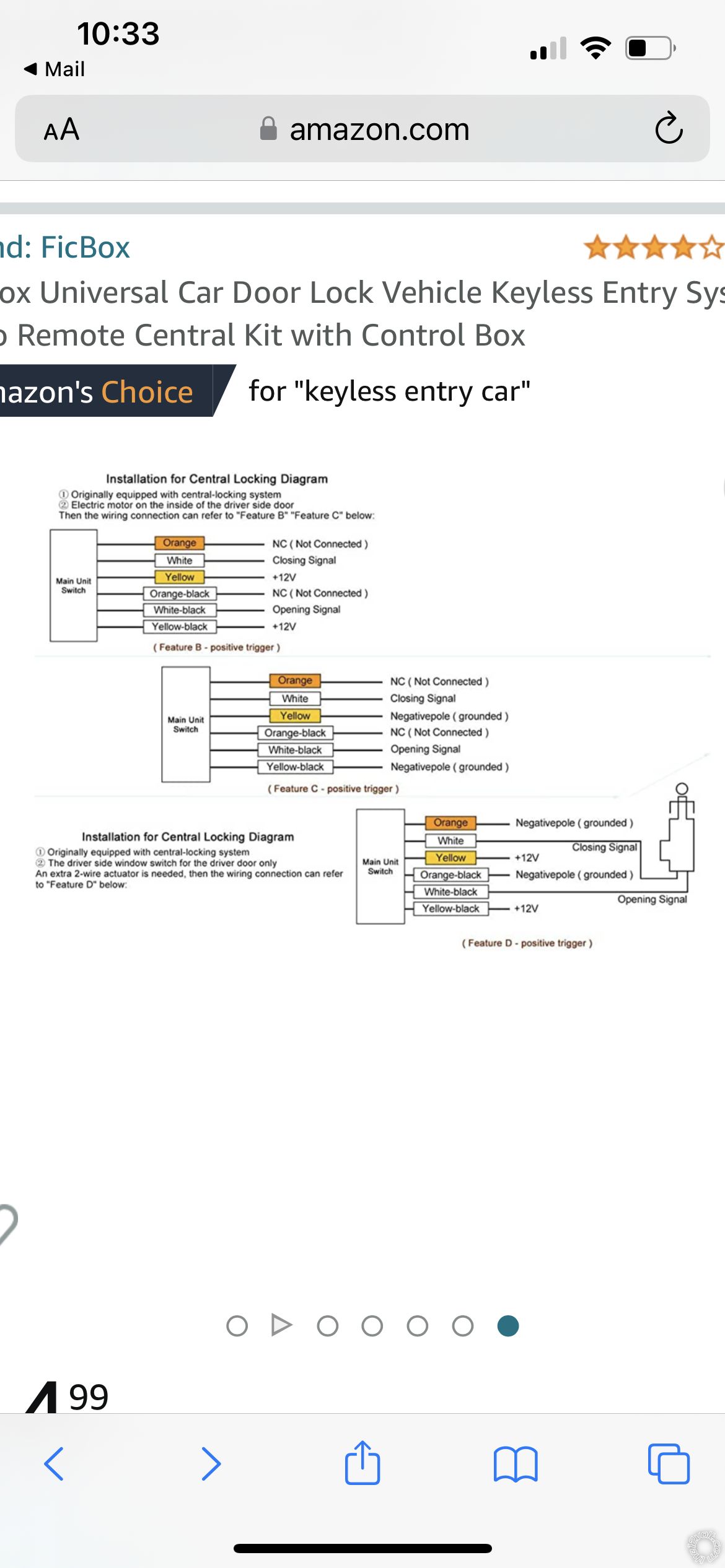
Your Honda has Type B locks. These require a (-) signal pulse to operate the solenoid. It looks like you would follow the middle diagram for proper operation in your car. Both the Yellow and Yellow/Black wire go to a good Chassis Ground and the White and White/Black would go to the proper wires listed below.
POWER LOCK PINK/BLACK (TYPE B) @ MICU*, GREEN Plug, Pin 25
POWER UNLOCK PINK/BLUE (TYPE B) @ MICU*, GREEN Plug, Pin 9
* The MICU (Multiplex Integrated Control Unit), is part of the underdash FUSE/RELAYBOX. The plugs for the MICU Module are on the LEFT SIDE EDGE of the RELAY/FUSE BOX.
Just a quick note : Ensure you use a Digital Multi Meter when testing any wire on the vehicle, especially when looking for the Trunk Release wire in the Drivers Kick Panel. It is very easy to kill the BCM in that car with improper testing or incorrect wire connections.
-------------
Soldering is fun!
In post 2 it says I need to follow the middle diagram for the door locks .
But at the bottom it says positive trigger on the diagram .
Do I need to buy 2 relays to switch it from positive trigger to negative trigger ?
The 3 different options all say positive trigger below the pics so Im confused do I need to switch the positive trigger over to negative trigger with relays ? Or hook it up as shown I dont wanna short anything out
-------------
Mike
While the diagram is rather vague* it would appear that the outputs are basically two relays, one for Lock and one for Unlock. The two sets of three output wires could be assigned the standard SPDT relay pin numbers as follows :
Lock Relay
Orange wire = Pin 87a
White wire = Pin 30
Yellow wire = Pin 87
Unlock Relay
Orange/Black = Pin 87a
White/Black = Pin 30
Yellow/Black = Pin 87
* Rather vague is being generous. Mis-labeled would be more accurate. Not unusual for "off-shore" systems translated to English.
The top diagram is for Type A (+) type door locks and outputs a (+) pulse. The middle diagram should be labeled Negative Output. The bottom diagram should be labeled "Direct lock solenoid control" and is very similar to the "5-wire" type diagram and control.
Anyway, what your vehicle needs is Type B (-) outputs being as it already has power locks and a factory control system. You are just adding another point of control ( the aftermarket system ).
You can put the new aftermarket system on the bench to test the suggested Type B wiring. Just connect the Yellow and Yellow/Black wires to Chassis Ground and then connect your DMM Black wire to the White wire. Set the DMM to 20 V DC and connect the DMM Red wire to +12V constant. Every time you press the Lock button on the aftermarket system FOB you should see +12V on the DMM. You can then switch the DMM Black lead to the White/Black wire and test using an Unlock command. Same results on the DMM. This proves the aftermarket system outputs a (-) pulse for Lock and Unlock. ( there will be other wires on the aftermarket system that need to be connected.)
No extra relays will be needed.
-------------
Soldering is fun!