Viper 5706V With Omegalink Bypass Module, 2007 Nissan Titan
Printed From: the12volt.com
Forum Name: Car Security and Convenience
Forum Discription: Car Alarms, Keyless Entries, Remote Starters, Immobilizer Bypasses, Sensors, Door Locks, Window Modules, Heated Mirrors, Heated Seats, etc.
URL: https://www.the12volt.com/installbay/forum_posts.asp?tid=148143
Printed Date: April 25, 2026 at 4:28 PM
Topic: Viper 5706V With Omegalink Bypass Module, 2007 Nissan Titan
Posted By: desert islander
Subject: Viper 5706V With Omegalink Bypass Module, 2007 Nissan Titan
Date Posted: September 06, 2024 at 9:53 PM
I will be installing a Viper RS/Alarm 5706V with a Omegalink OL-MDB-ALL bypass module using the (D2D) data to data connection instead of the wired method on my 20007 Nissan Titan. I have the diagrams for both, however the Omegalink wiring diagram shows a generic remote starter.
1. What wires are needed from the Viper 5706V using the D2D connection mode?
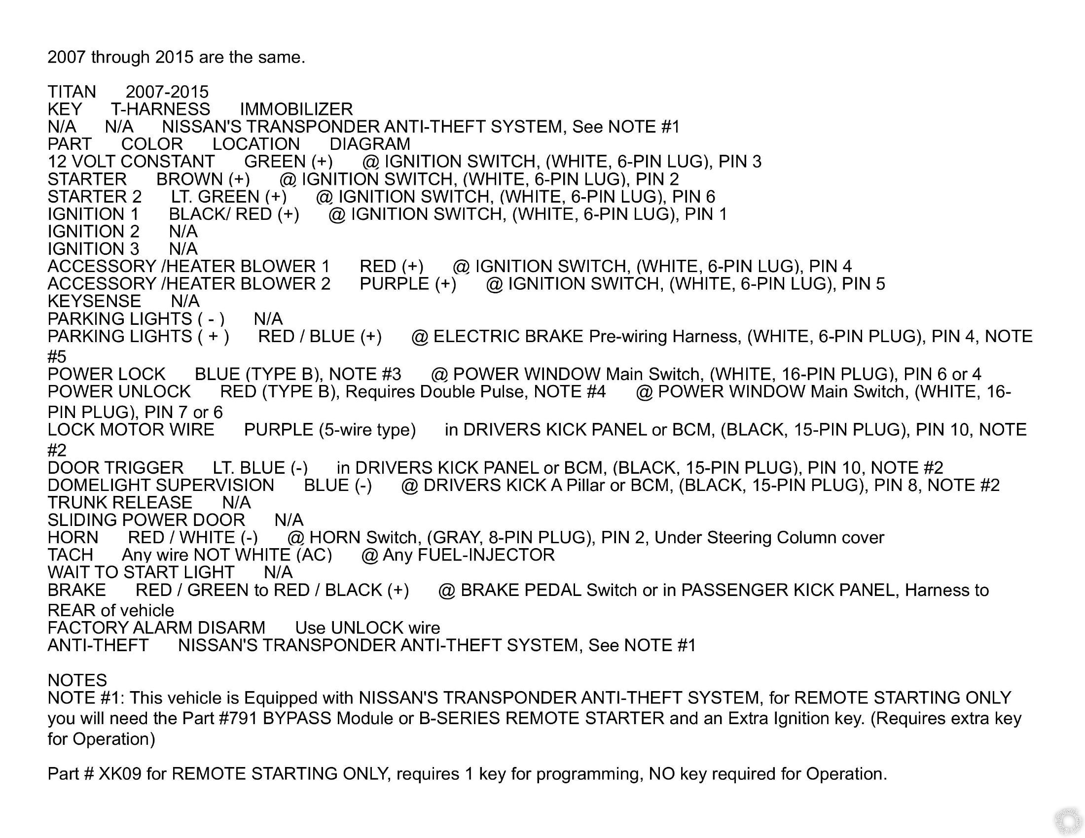
2. The Viper RS 10-pin connector pin 6 starter input and pin 7 starter output shows to connect the input to the key side of the starter kill
and the output to the car side of the starter kill. On the Titan wiring diagram, is this connected to the starter brown wire at ignition
switch (white 6 pin lug) pin 2? And the starter 2 light green wire at ignition switch (white 6 pin lug) pin 6 is not used?
3. The12volt Nissan wiring diagram shows NA for ignition 2 and ignition 3 but on the Viper RS 10 pin connector wiring diagram it shows pin
4 (+) ignition 2 / flex relay output and pin 9 (+) fused 12v ignition 2 / flex relay input 87. Does this get connected or is this also not
used?
 ------------- desertislandertech
Replies:
Posted By: desert islander
Date Posted: September 06, 2024 at 9:56 PM
I have a typo of the year of my 2007 Titan not 20007.
-------------
desertislandertech
Posted By: lee.lopez
Date Posted: September 07, 2024 at 1:21 AM
1) D2D only handles the functions in the dashed red lines. The solid black lines are still required connections. You will also have to connect the power, ground, ignition wires, etc.
2) If you prefer to use the built in starter kill relay, cut the starter 1 wire at the ignition switch and connect the green wire to the key side and the purple wire to the starter side.
If you don't want starter kill, just connect the purple wire to the starter 1 wire and you're good to go. For starter 2 see my response to 3) below.
3) You can change the flex relay (pink/white) to starter2. Menu 3, item 8, option 3.
It's easiest to use a Bitwriter or XKLoader3 in Bitwriter mode, but you can do it with the key/valet button/remote.
Be sure to connect all red fused wires (red, red/black, red/white).
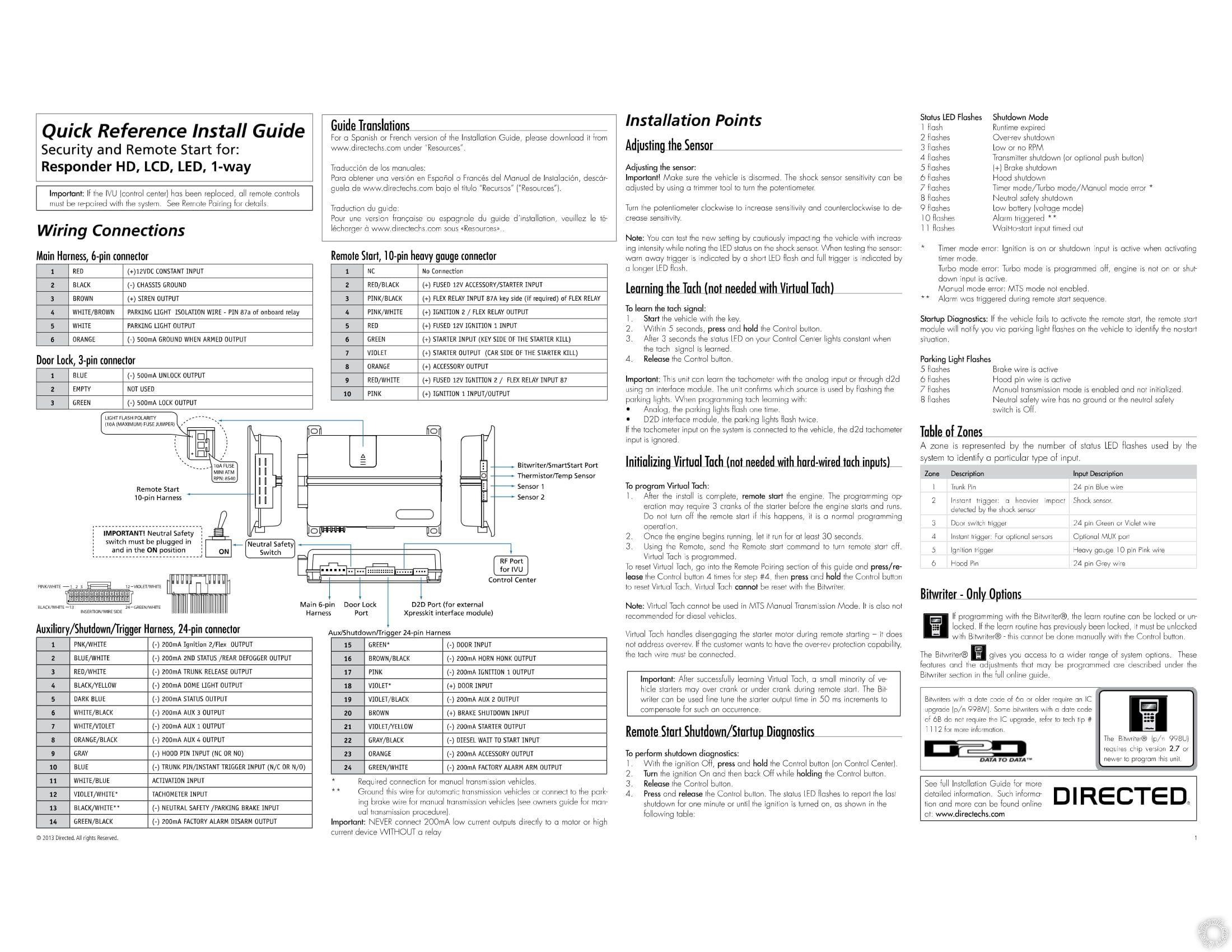
*Also, download the installation manual from the download section on this site if you don't have it: https://www.the12volt.com/installbay/file.asp?ID=1341
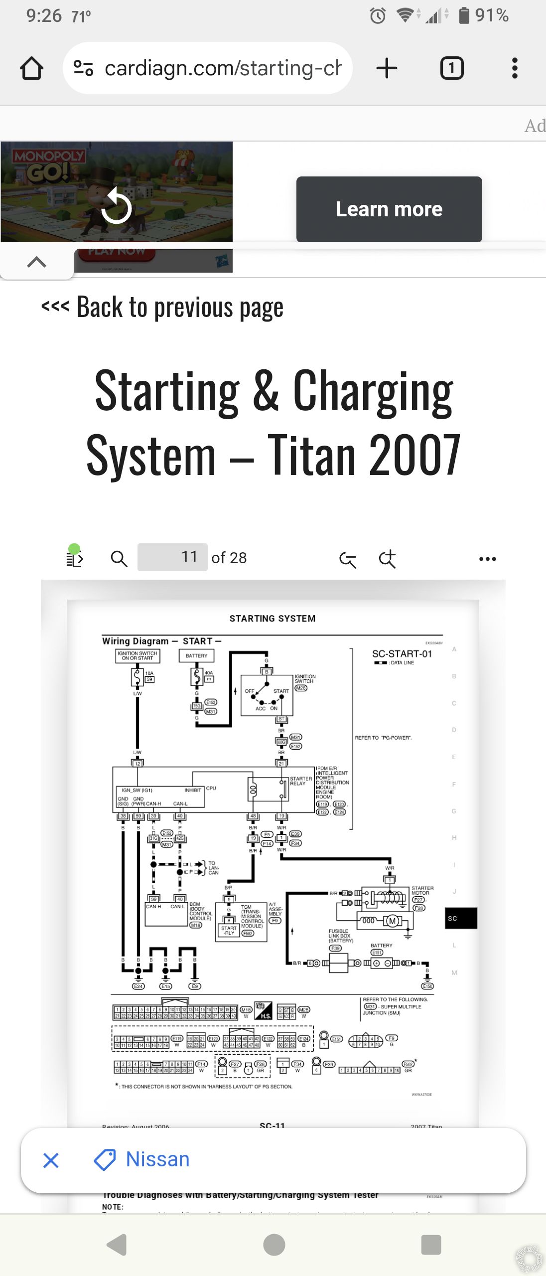
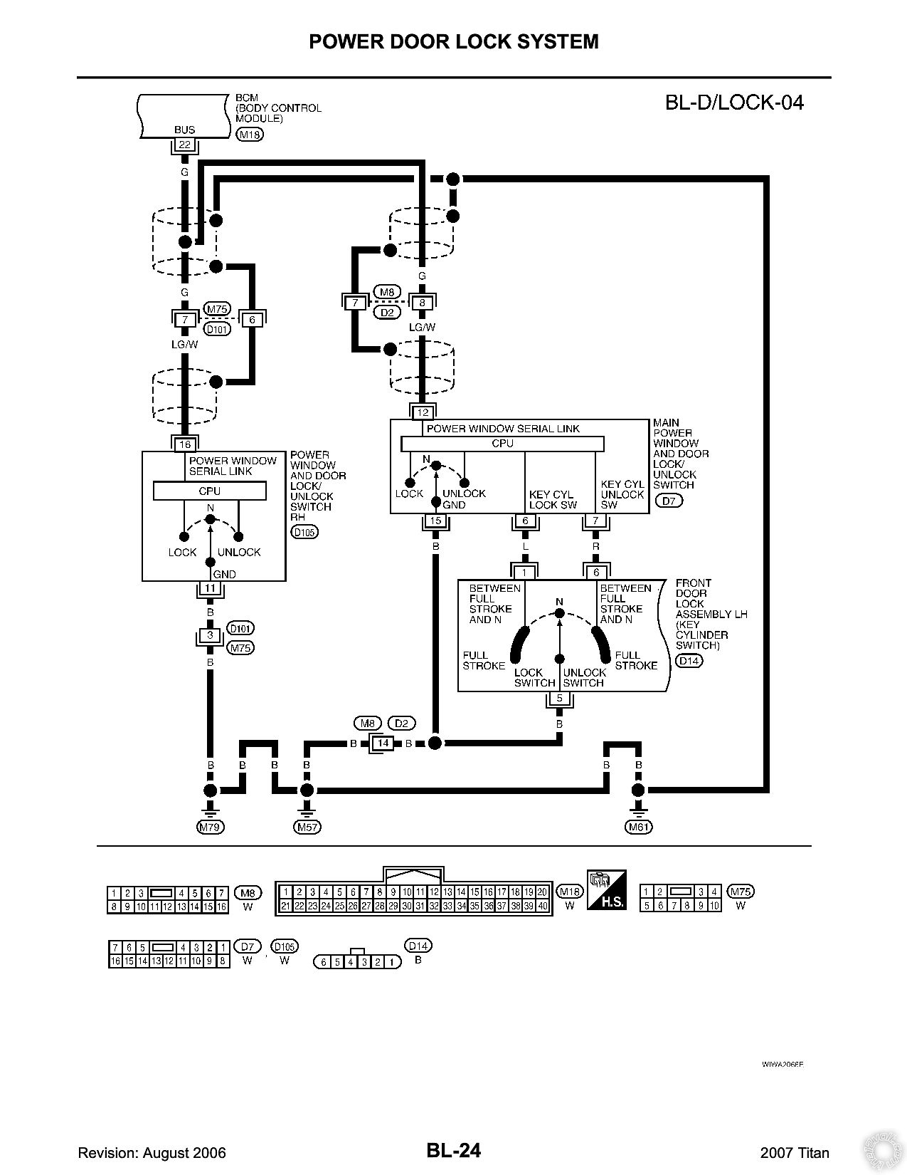
It's kind of interesting there's no starter 2 wire in the factory wiring diagram:
Posted By: desert islander
Date Posted: September 07, 2024 at 1:15 PM
Thanks for the quick response.
I will be using the starter kill therefore I will cut the starter 1 wire at the ignition switch and connect the green wire to the key side and the purple wire to the starter side. I'm confused with the starter 2. Are you saying the pink/white wire from the 10 pin connector on the RS (+) ignition 2 / flex relay output needs to be connected to the starter 2 wire at the ignition lt. green (+) @ ignition switch (white 6 pin lug) pin 6 and then change the flex relay (pink/white) to starter2 during programming (Menu 3, item 8, option 3)?
For the RS light flash polarity on my Titan, I believe it is positive, correct? I would use the positive jumper not negative.
-------------
desertislandertech
Posted By: lee.lopez
Date Posted: September 07, 2024 at 5:10 PM
Yes to both. You will be programming the pink/white to starter2 and making sure the parking light jumper is set to positive.
Posted By: desert islander
Date Posted: September 07, 2024 at 10:19 PM
Just so I understand this correctly.
RS Main Harness, 6-Pin Connector:
1, 2 and 3 are hard wired.
4, 5, and 6 are not needed. Connected through D2D.
RS Door Lock 3-Pin Connector:
1, 2, and 3 are not needed. Connected through D2D.
RS 10-Pin Heavy Gauge Connector:
2-10 all hard wired.
RS Auxiliary/Shutdown/Trigger Harness 24-Pin Connector:
1-24 not needed. Connected through D2D.
-------------
desertislandertech
Posted By: lee.lopez
Date Posted: September 08, 2024 at 12:33 AM
Just so I understand this correctly.
RS Main Harness, 6-Pin Connector:
1, 2 and 3 are hard wired.
4, 5, and 6 are not needed. Connected through D2D.
Correct about 1, 2 and 3. Also connect 5 if you want parking lights as it's not listed as supported by D2D.
RS Door Lock 3-Pin Connector:
1, 2, and 3 are not needed. Connected through D2D.
Correct.
RS 10-Pin Heavy Gauge Connector:
2-10 all hard wired.
Correct.
RS Auxiliary/Shutdown/Trigger Harness 24-Pin Connector:
1-24 not needed. Connected through D2D.
For the most part, yes. Nothing else is required. However if you want to connect an aux output you need to hardwire it.
Posted By: desert islander
Date Posted: September 08, 2024 at 12:57 AM
I see there are 1-4 Aux outputs on the 24 pin connector. What are they used for and where would they be connected to?
I also noticed on the 24 pin connector that there is an ignition 1 and 2 output and a starter output. Do these need to be hardwired or is this through the D2D as well?
-------------
desertislandertech
Posted By: lee.lopez
Date Posted: September 08, 2024 at 7:52 AM
The aux outputs can be used for whatever you want. Maybe you want to use one to turn on your headlights for a set amount of time, or one to open your garage door. It's up to you. They are optional.
In your case, you don't need the negative ignition or starter wires. Some vehicles have 3 ignition wires, so you could use one to trigger another relay.
Posted By: desert islander
Date Posted: September 08, 2024 at 10:03 AM
Okay got it. Thanks for the installation support.
-------------
desertislandertech
Posted By: desert islander
Date Posted: September 12, 2024 at 10:02 PM
Hey Lee, you mentioned above to be sure to connect the red, red/white and red/black fused wires.
The viper wiring diagram shows the red/black fused wire connects to the accessory/starter input, the red fused wire connects to ignition 1 input and the red/white fused wire connects to ignition 2/flex relay input 87. According to the wiring diagram for my Titan there isn't an ignition 2 input.
-------------
desertislandertech
Posted By: lee.lopez
Date Posted: September 13, 2024 at 2:00 PM
It's a little confusing how Viper words the manual. All the red fused wires connect to constant 12 volt power. When it says ignition 2 input, it just means it's the power to feed the internal circuit, which you are reprogramming to Starter 2.
Posted By: desert islander
Date Posted: September 14, 2024 at 12:15 AM
The Viper diagram has one wire on the 6-pin main harness connector that specifically shows to connect the red 12v constant input to a constant 12v circuit at the ignition. Are you saying that this 12v constant wire connects with all the other three fused wires together from the 10-pin heavy gauge connector even if the diagram shows that the red/black fused wire connects to the accessory/starter input, the red fused wire connects to ignition 1 input and the red/white fused wire connects to ignition 2/flex relay input 87?
-------------
desertislandertech
Posted By: lee.lopez
Date Posted: September 14, 2024 at 3:15 AM
The quick start guide you have is more of a reference for installers that are familiar with Viper systems, so it doesn't go into that much detail.
Yes, I'm saying they all need to be connected to constant 12 volts, which is why they are all fused. The thick fused wires provide power to the relays that are built into the Viper. These relays connect to the starter, accessory and ignition wires. What I've often done is connected the red wire in the main harness to one of the fat red wires in the remote start harness.
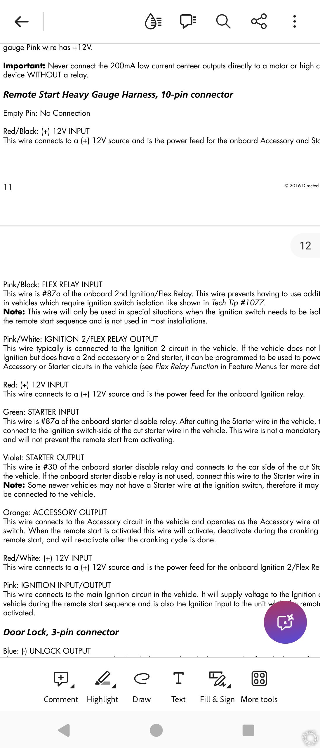
See pages 11 and 12 of the complete installation manual. Here's the link again in case you haven't downloaded it: https://www.the12volt.com/installbay/file.asp?ID=1341
You'll see that the red/black wire provides power to the starter. If you do not connect this wire to constant 12 volts you will not be able to remote start because it is the power source for the Viper's on board starter relay. The red/white wire provides power to the flex relay (which is ignition 2 by default). Notice this wire is labeled as #87 which is the normally open contact on a standard 12 volt automotive relay.
Posted By: desert islander
Date Posted: September 14, 2024 at 11:27 AM
Okay I got it. Now on the RS 10-pin heavy gauge harness there is the pink/black (+) flex relay input 87A key side (if require) of flex relay. Where does this connect to?
This is from the link you sent.
Pink/Black: FLEX RELAY INPUT
This wire is #87a of the onboard 2nd Ignition/Flex Relay. This wire prevents having to use additional relays in vehicles which require ignition switch isolation like shown in Tech Tip #1077.
Note: This wire will only be used in special situations when the ignition switch needs to be isolated during the remote start sequence and is not used in most installations.
-------------
desertislandertech
Posted By: lee.lopez
Date Posted: September 14, 2024 at 1:08 PM
Not used in your setup. You can tape it off or remove it from the harness if you want.
Posted By: desert islander
Date Posted: September 15, 2024 at 4:15 PM
On RS 6-pin main harness parking light output will connect to parking light positive red/blue at electric brake harness pre-wiring harness (white 6-pin plug) pin-4, is this correct?
-------------
desertislandertech
Posted By: lee.lopez
Date Posted: September 15, 2024 at 5:00 PM
Yes, that's what I'm seeing. You can verify with a multimeter.
One more thing- make sure you program for automatic transmission (manual is default).
Posted By: desert islander
Date Posted: September 15, 2024 at 9:28 PM
Will do thanks for catching that.
-------------
desertislandertech
Posted By: desert islander
Date Posted: September 18, 2024 at 11:52 AM
I have a hood pin for this installation. There is a gray (-) hood pin input (NC or NO) on the RS 24-pin Auxiliary/shutdown/trigger. Will I need this wire for the hood pin if connecting D2D?
-------------
desertislandertech
Posted By: lee.lopez
Date Posted: September 18, 2024 at 6:16 PM
This is not handled by D2D as hood is not annotated by the red dashed lines and I don't see one on any factory diagrams.
You will need to run this yourself if you want it as an input for your system. The hood pin switch does two things:
1) It triggers the alarm if the hood is popped while armed.
2) Shutdown the remote start
Posted By: desert islander
Date Posted: September 18, 2024 at 8:06 PM
I missed the hood pin when I asked about the RS Auxiliary/shutdown/trigger harness 24-pin connector question. Then I will need the 24-pin harness connector for this one wire after all. What about brake shutdown input, neutral safety/parking brake input and horn honk output on the 24-pin harness will I need to hard wire these or is this already connected through the D2D? I don't see horn honk output on D2D and not sure if brake status is the same as brake shutdown and E-parking brake is the same as neutral safety/parking brake.
-------------
desertislandertech
Posted By: lee.lopez
Date Posted: September 18, 2024 at 8:22 PM
If you want horn honk you will need to hardwire it also. Brake (status/shutdown) and e-brake should both be handled D2D. If for whatever reason this doesn't work you can hardwire those also.
Sometimes I'll leave some extra wire just in case I need to make changes later.
Posted By: desert islander
Date Posted: September 18, 2024 at 8:45 PM
Got it thanks. I'll leave the rest of the unused wires intact in case I need it down the road.
-------------
desertislandertech
Posted By: desert islander
Date Posted: September 22, 2024 at 5:43 PM
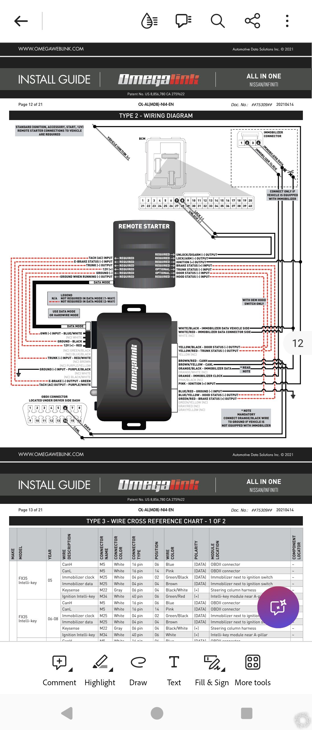
I was wondering if factory alarm arm (green/white) and disarm (green/black) on the Auxiliary/shutdown/trigger 24-pin harness is required if I have a factory alarm? Omegalink bypass type-2 wiring diagram shows this goes to the BCM M18 connector 7 (disarm) and 8 (arm) pins but will need to be pinned since these two points are empty at the BCM M18 connector.
-------------
desertislandertech
Posted By: lee.lopez
Date Posted: September 22, 2024 at 8:33 PM
If they don't show as controlled functions by the interface then you may be able to get some pigtail BCM connectors on eBay or a junkyard. Then you'll have the pins you need for the empty slots.
Posted By: desert islander
Date Posted: September 27, 2024 at 3:51 PM
Is there an easy way to identify the correct size of the pin crimp connector to order for the BCM M18 harness? I also found a wiring diagram for 2007-2015 wiring diagram for RS. It shows for the factory alarm disarm to use the unlock wire but on the viper RS installation instruction and the Omegalink bypass diagram it shows to connect the lock/unlock negative wire from the RS auxiliary/shutdown/trigger 24-pin harness to the BCM. It's kind of confusing.
 ------------- desertislandertech
Posted By: lee.lopez
Date Posted: September 27, 2024 at 4:40 PM
You might make friends with a Nissan tech. I couldn't find anything. But if you get BCM pigtails from a junkyard or eBay you'd have them.
In order to try the unlock wire at the window switch you'd have to run wires into the door.
Posted By: desert islander
Date Posted: September 27, 2024 at 10:39 PM
I'm assuming your saying that these BCM pigtails are the same size for all vehicles is that correct?
Could I run the unlock wire only to the door and not the lock wire from the RS 24-pin to avoid the need to run the lock/unlock negative wires to the BCM?
If I don't connect the lock/unlock negative wires from the RS to the BCM would this affect the RS in any way from working?
-------------
desertislandertech
Posted By: lee.lopez
Date Posted: September 28, 2024 at 3:48 AM
I'm saying if you get some pigtails for your year/make/model BCM you'll have the female pins. Or you could check the dealer website to see what years use the same BCM.
If you search this on eBay it looks like the same connector so you could de-pin and get a couple female pins: "OEM 2007-2015 NISSAN TITAN BODY CONTROL MODULE BCM CONNECTOR A".
If lock is working, I don't see a need to connect a wire for lock, but you'd still need to connect one for disarm. You could verify the function of the factory disarm wire with a multimeter. Then with the window switch still removed but plugged in to the door harness, you could temporarily use a jumper wire to pulse to ground prior to remote start. If this works you could just run your wire into the door.
Posted By: desert islander
Date Posted: October 03, 2024 at 11:57 AM
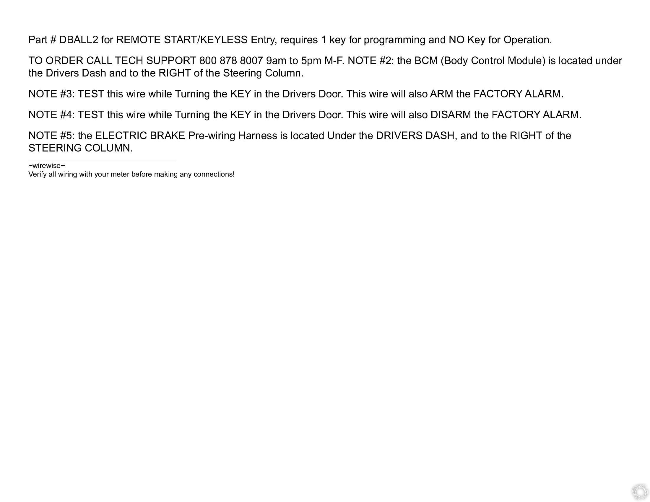
Could I hardwire all required wires with the exception of the RS 24-pin green/black factory alarm disarm output and green/white factory alarm arm output wires until I get the pigtails and still program the RS/alarm to function properly? If this will still work without connecting these two wires do I need to reprogram the RS/alarm once I do get it connected? I will also be looking at connecting these wires to the power door lock/unlock as shown on the wiring diagram for my Titan. It shows on Note #3 that the power lock (blue) wire will arm the factory alarm and Note #4 shows that the power door unlock (red) wire will disarm the factory alarm. If this works then I won't need to connect to the BCM pin 7 & 8 harness connector M18. Is this correct?
-------------
desertislandertech
Posted By: lee.lopez
Date Posted: October 04, 2024 at 5:02 PM
I couldn't tell you how it would work with the Omegalink as I've never used them. But yes, if the wires at the power window switch work, you wouldn't need any pigtails.
Posted By: desert islander
Date Posted: October 13, 2024 at 1:13 PM
I finally got around to connecting my RS. Does learning the virtual tach need to be programmed before RS will work? When I press the RS side button on the key fob, display shows an error. I can hear the RS clicking 8 times but nothing turns on at the dash and my truck does not start. The door lock/unlock function on the key fob doesn't work either. I changed all the settings in Menu 3-Remote Start feature 1 (Transmission Mode) option 2 (Automatic) and feature 8 (Flex Relay Function) option 3 (Starter 2).
-------------
desertislandertech
Posted By: lee.lopez
Date Posted: October 13, 2024 at 4:06 PM
It would be worth trying, but if you get a remote start error that likely needs to be addressed first.
8 flashes means Neutral safety shutdown. Are you sure it's not 7 flashes (manual mode error)?
Posted By: desert islander
Date Posted: October 13, 2024 at 6:26 PM
Looking at the viper RS install guide 24-pin harness it shows that the Black/White (-) neutral safety/parking brake input wire needs to be connected to ground for automatic transmission. I thought that because I connected via D2D that this wire is not used but apparently it seems that I do need to connect it. Could this be the problem?
To be more specific, I am hearing 8 clicks that sound like it is coming from underneath the dash assuming from the RS. The RS control center button installed at top of windshield is not flashing. Sounds like a relay clicking underneath the dash.
-------------
desertislandertech
Posted By: lee.lopez
Date Posted: October 13, 2024 at 9:01 PM
Yes, that is most likely the issue. Ground that wire and you should be good to go.
If your parking lights are connected and working you can always watch for flashes.
Posted By: desert islander
Date Posted: October 14, 2024 at 1:34 PM
Looking back on the viper RS installation guide, the one that came with the RS is dated 2016. This new guide shows 24-pin harness Black/White wire is (-) parking/E-brake input and to connect this wire to the (-) parking brake wire in the vehicle.
The older version dated (2013) that I found online that I was looking at for the viper RS shows the same Black/White wire (-) neutral safety/parking brake input to ground this wire for automatic vehicles.
Now on the viper RS 5706 RS installation guide found on the Directed website dated (2015) shows the Black/White wire (-) neutral safety/parking brake/E-brake input.
The RS installation guide dated 2013 says the black/white wire is connected to ground for automatic transmissions.
The RS installation guide dated 2016 says the black/white wire is connected to the (-) parking brake wire in the vehicle and says the same for the Directed website viper RS installation guide dated 2015.
Do I connect the black/white wire to the parking brake wire on the vehicle since this is the newer version (2016) of the installation guide or do I still connect this wire to ground as shown on the 2013 guide?
Startup diagnostics on the viper RS guide dated 2013 says the 8 flashes (parking lights) means the neutral safety wire has no ground.
On the guide dated 2016 this means Parking/E-brake wire (RS harness black/white wire) has no ground. I'm not sure what the difference is between the two guides and if this is the same thing for both guides to connect the black/white wire to ground.
-------------
desertislandertech
Posted By: lee.lopez
Date Posted: October 14, 2024 at 3:43 PM
If it were me, I'd just ground it. It is, after all an automatic.
Posted By: desert islander
Date Posted: October 14, 2024 at 8:06 PM
I connected the black/white to ground and now I have power at the dash but still no remote start. No error message on the key fob or no flashing parking lights to identify diagnostics. Lock/unlock still does not work when I use the key fob. I am starting to wonder if the Omega D2D is compatible with the viper RS.
-------------
desertislandertech
Posted By: lee.lopez
Date Posted: October 14, 2024 at 8:26 PM
Did you learn tach like you had asked about? If not, try that and then see if it remote starts.
Posted By: desert islander
Date Posted: October 14, 2024 at 9:42 PM
I have not but will try learning the tach and see if that fixes the issue.
-------------
desertislandertech
Posted By: desert islander
Date Posted: October 15, 2024 at 6:27 PM
On the viper RS quick reference installation guide, it shows an important note regarding the neutral safety switch must be plugged in and in the on position, but I did not receive one with my viper RS. Is this switch required for RS?
I also tried to learn the tach following the RS guide, but it didn't work. I started the vehicle and within 5 seconds pressed and held the control center button for 3 seconds or more, but the light didn't come on. I didn't even see the parking lights blink.
-------------
desertislandertech
Posted By: lee.lopez
Date Posted: October 15, 2024 at 7:09 PM
The layout picture with that note shows a 2-pin plug between the 6-pin main harness and the 3-pin door lock harness. Do you have this 2-pin plug there? If you do, you can put a small jumper from an old computer or a crossover there and try again.
Posted By: desert islander
Date Posted: October 15, 2024 at 8:26 PM
Are all two pin computer connectors the same size? Yes, there is the two pin port by the 6-pin main harness.
-------------
desertislandertech
Posted By: lee.lopez
Date Posted: October 15, 2024 at 9:32 PM
Yes, if you have that there, those 2 pins need to be jumped. That's what the plug in toggle switch is supposed to do but since you're missing it, a standard .1" jumper will work.
Posted By: desert islander
Date Posted: October 18, 2024 at 10:03 PM
Okay so I checked the viper 5706v and verified that I don't actually have the 2-pin port by the 6-pin main harness for the neutral safety switch. I'm assuming they removed this 2-pin port connection at some point during production and isn't needed. When I press the remote start on the key fob the dash lights come on but still no RS. Although it does show on the key fob that RS is active with the 12min timer, but engine doesn't crank. I'm also trying to troubleshoot lock and unlock for the viper key fob. Lock/unlock doesn't work even though it shows lock/unlock on the key fob. The alarm function works for arm/disarm when I press lock/unlock on the key fob. Any idea on why I can't get the RS to work?
-------------
desertislandertech
Posted By: lee.lopez
Date Posted: October 19, 2024 at 5:29 AM
Meter the fat purple wire in the remote start harness for 12 volts during remote start. Do you get a reading?
Posted By: desert islander
Date Posted: October 19, 2024 at 2:04 PM
That would be the starter wire vehicle side, is that correct?
-------------
desertislandertech
Posted By: lee.lopez
Date Posted: October 19, 2024 at 2:28 PM
Yes
Posted By: desert islander
Date Posted: October 19, 2024 at 5:11 PM
No 12 volts on purple wire (starter) vehicle side during RS. I also checked the green wire (starter) key side no 12 volts there either during RS. 12 volts at the orange wire accessory and pink wire ignition 1 10-pin heavy gauge connector. No 12 volts on pink/white wire at starter 2 (light green wire at ignition).
-------------
desertislandertech
Posted By: lee.lopez
Date Posted: October 19, 2024 at 8:08 PM
You mentioned no starter output but have power on accessory. That means the fuse on the red/black wire is good.
Sounds like the starter output on the Viper is bad. Check the fuse on the red/white wire.
When you try to remote start, you can jump power to the starter wire and see if it starts and runs. If it does, you can try using the negative starter output wire (purple/yellow pin 21) to trigger a relay and connect the output to the vehicle starter wire.
Posted By: desert islander
Date Posted: October 20, 2024 at 1:16 PM
30-amp fuse is good on red/white. This wire is labeled as 12-volt constant power feed for the onboard ignition 2/flex relay input.
What do you mean by jumping power to the stater wire and where do I jump it from?
Could I jump from the 12-volt constant, or do I need to get this from somewhere else?
If this does work, do I need a separate relay or could I use the onboard relay to trigger the starter wire assuming the car side purple wire?
I also still have not figured out the lock/unlock for the viper key fob. It still doesn't work. Only work for alarm arm/disarm function.
-------------
desertislandertech
Posted By: lee.lopez
Date Posted: October 20, 2024 at 1:58 PM
Yes, you could jump it from constant or ignition power, but only momentarily. This is just a test. If it starts and runs, then see if the negative starter output will trigger a relay.
Yes, you would use a separate relay.
Have you tried the wires at the power window switch?
Posted By: desert islander
Date Posted: October 20, 2024 at 3:30 PM
Ok I will try that but can I leave the starter kill purple connected while performing this test? Is there no way to use the onboard relay and programming this in menu?
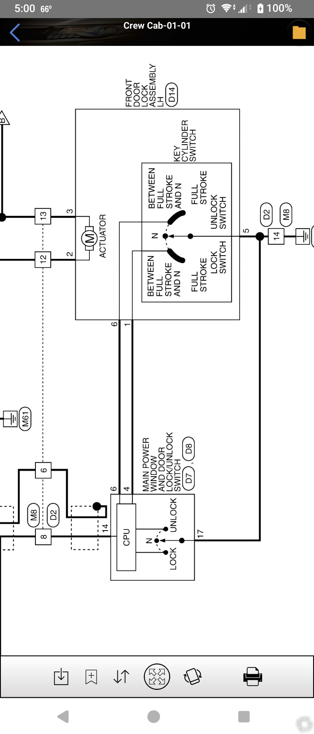
I'm still trying find the correct wires at the door. I checked the 16-pin connector at the window switch but can't seem to identify the correct wires. The wiring diagram says to check the power lock Blue (type b) pin 6 or 4 and power unlock Red (type B) pin 7 or 6 and requires a double pulse. I'm not sure what type B means though. Note for both says to test these wires while turning the key in the drivers door and that this will
arm and disarm the factory alarm. I tested all wires at the connector and none of them show any change.
-------------
desertislandertech
Posted By: lee.lopez
Date Posted: October 20, 2024 at 4:31 PM
This is just a test to see if it will work. Leave the wiring as is for now. If you're not getting an output from the Viper, how do you plan to use the onboard relay? Since this is a DIY system, it's not like you can swap out the unit for a replacement. You need to either work around it or buy another one.
If it doesn't work you can still add starter kill: https://www.the12volt.com/relays/relaydiagram10.html
Type B is negative switched. Connect your red meter lead to a constant 12 volt source. Connect your black lead to your test wire. Set your meter to read DC volts. Turn and hold the key in the driver door while watching the reading. The wire that gives you a normal reading at 0 volts and only reads 12 volts when you turn the key is the one you want.
Posted By: desert islander
Date Posted: October 20, 2024 at 4:48 PM
Got it. Hopefully this works.
Going to test the door wires. Thanks for making this test easier to understand.
-------------
desertislandertech
Posted By: desert islander
Date Posted: October 22, 2024 at 9:34 PM
I haven't had the chance to perform the starter jump test.
I was able to test the door lock wires. I found the lock/unlock wires but when I put the red lead from the MM to a 12-volt source and the black lead to the lock/unlock wires it tested 6.8 volts before turning the key and 11.8 volts when turning the key. This test is the same for both lock pin-4 and unlock pin-6.
 ------------- desertislandertech
Posted By: lee.lopez
Date Posted: October 22, 2024 at 9:51 PM
Perfect, you found your lock wires then. I realize I said they will show 0 volts, but this is not necessarily the case. A 5 volt system like yours would show a difference of around 7 volts (your 6.8 volt reading) and then 12 volts (11.8 volts) when you turn the key.
Posted By: desert islander
Date Posted: October 23, 2024 at 11:33 AM
I'm trying get back in to the RS programming via the control center but nothing happens like its locked out. I am able to turn on and off valet mode but thats all. I need to get back in to programming to verify menus 1, 2, and 3 programmimg I changed.
-------------
desertislandertech
Posted By: lee.lopez
Date Posted: October 23, 2024 at 11:46 AM
Door trigger and ignition need to be connected.
Door open, key on, key off, hold valet down and watch for flashes/listen for honks.
Posted By: desert islander
Date Posted: October 23, 2024 at 12:26 PM
Are you referring to 24-pin harnees H2/15 negative green (door input) or H2/18 positive violet (purple) (door input) wire.
And for the ignition is this the same as H3/10 positive ignition input/output that is already connected or are you referring to the H2/17 negative pink 200mA ignition 1 output wire.
Do both of these need to stay connected? When you say connected, do you mean grounded to chasis?
-------------
desertislandertech
Posted By: lee.lopez
Date Posted: October 23, 2024 at 12:52 PM
Yes, either connect the green or purple door trigger depending on the vehicle trigger polarity.
The pink ignition input/output in the remote start harness needs to be connected.
These need to be hooked up during programming so the brain knows the door is open and key on/off. Otherwise it won't enter programming mode.
Posted By: desert islander
Date Posted: October 23, 2024 at 9:06 PM
The wiring diagram for my truck shows that the door trigger wire is Lt. blue (negative) in drivers kick panel or at the BCM. Do I need to connect the green wire to the Lt. blue wire at the kick panel or could I just ground it to the chasis?
The RS pink ignition input/output wire at the 10-pin harness is already connected when I installed the RS/alarm.
I don't get how I was able to program the RS after installation without connecting the green door input wire first. I assumed that because I installed the RS using D2D connection that this wire was not needed.
Could I connect the door lock/unlock wires at the drivers kick panel if I traced it from the main door switch? I would rather connect it this way than to run wires into the door.
-------------
desertislandertech
Posted By: lee.lopez
Date Posted: October 24, 2024 at 5:03 AM
You can at least jump the green door trigger to ground temporarily to see if you can get into programming.
The wires you found for the door locks are not listed to run inside the cabin, only between the key cylinder switch and the power window/lock switch so you will likely need to run wires into the door.
Posted By: desert islander
Date Posted: November 26, 2024 at 8:39 PM
Well, I'm back again. I am happy to say that I managed to get the lock/unlock functions to work. I am also able to get back in to programming features for the RS via the control center.
I still have an issue with the RS working though. I did the test you mentioned above, and it cranked over however will not start. Message on the RS key fob still showing that vehicle is on and also displays the timer of 12 mins. I verified programming and made sure that I have it programmed for automatic. I don't know what else I need to check why I can't get the RS start to work. Alarm functions work fine though so it's just starting the vehicle that doesn't work.
-------------
desertislandertech
Posted By: lee.lopez
Date Posted: November 27, 2024 at 4:31 AM
Try putting the key in the ignition and remote starting. You may still have to jump power to the starter wire. Does it start and run?
Posted By: desert islander
Date Posted: November 27, 2024 at 12:07 PM
Do I need to turn the key to ACC or ON before I attempt to remote start or just insert key and not turn?
-------------
desertislandertech
Posted By: lee.lopez
Date Posted: November 27, 2024 at 1:15 PM
No, just insert it and leave the key in the off position.
If you can successfully remote start with the key in, it means your bypass isn't doing it's job.
Silly question - was your bypass flashed?
Posted By: desert islander
Date Posted: November 27, 2024 at 2:21 PM
Okay that's what I thought also for this test. Yes, my bypass was flashed but was also thinking maybe it's the bypass module. Going to try this before a reflash if it does work with key in ignition.
-------------
desertislandertech
Posted By: desert islander
Date Posted: November 28, 2024 at 1:29 PM
Happy Thanksgiving to you and your family!!
I attempted to RS with key in ignition and also used momentary jump start. The truck did start however after a few seconds I heard what sounds like grinding of the starter. I have all the wires connected as shown in the RS wiring diagram.
Assuming that I have to re-flash the bypass module since it did start with the key in the ignition?
What about the grinding that sounds like it came from the starter?
-------------
desertislandertech
Posted By: lee.lopez
Date Posted: November 28, 2024 at 5:53 PM
Yes. Reflash the bypass.
I'd see if you have an output at the negative starter wire. If you do, you can wire a relay for starter output.
Posted By: desert islander
Date Posted: November 29, 2024 at 8:18 PM
Are you referring to the violet/yellow negative 200mA starter output from the RS auxiliary/shutdown/trigger harness 24-pin connector?
When I reflash the bypass module, will it overwrite the old flash download?
-------------
desertislandertech
Posted By: lee.lopez
Date Posted: November 30, 2024 at 4:40 AM
Yes to both.
Since your bypass is an ADS brand, I'm assuming it's like Idatalink in that it'll tell you what firmware is installed when you connect to the flashing software. Yours should show OL-AL(MDB)-NI4.
Posted By: desert islander
Date Posted: November 30, 2024 at 11:34 AM
If I have 12 volts on the negative violet/yellow starter output wire during RS I can use this with a relay to connect to the car side of the starter at ignition, correct?
Do I leave the purple (violet) wire connected if I am connecting a relay or can I disconnect it and is no longer needed.
BTW, I was reading through the RS Directed installation guide menu 3 feature 13 anti-grind output has a note: Anit-grind feature works in conjunction with the orange GWA wire in the main 6-pin connector. I did not connect this wire. Is this the reason I heard a grinding noise that sounds like the starter grinding a few seconds after my truck started? I immediately shutdown the truck when I heard that sound.
-------------
desertislandertech
Posted By: desert islander
Date Posted: November 30, 2024 at 12:31 PM
After reflashing the bypass module and programming successfully, when I attempted to remote start, I had an error come up on the key fob display and 5 flashes from the parking lights. Startup diagnostics shows 5 flashes brake light is active. I didn't change anything else, so this is a new error.
-------------
desertislandertech
Posted By: lee.lopez
Date Posted: November 30, 2024 at 12:49 PM
Do you have the brake wire connected, or is this handled by the bypass? If you've verified it's 5 flashes and your brake wire is connected, try disconnecting it temporarily and seeing if it remote starts.
Posted By: desert islander
Date Posted: November 30, 2024 at 1:08 PM
No I do not have the brake wire connected.
Could you akso respond to previius question to this my last post regarding anti-grind?
-------------
desertislandertech
Posted By: lee.lopez
Date Posted: November 30, 2024 at 1:30 PM
If I have 12 volts on the negative violet/yellow starter output wire during RS I can use this with a relay to connect to the car side of the starter at ignition, correct?
This wire should show ground (not 12 volts) during remote start, which you use to trigger a relay and connect to the starter wire.
Do I leave the purple (violet) wire connected if I am connecting a relay or can I disconnect it and is no longer needed.
You can leave it for now while testing, but if this works it will not be needed.
BTW, I was reading through the RS Directed installation guide menu 3 feature 13 anti-grind output has a note: Anit-grind feature works in conjunction with the orange GWA wire in the main 6-pin connector. I did not connect this wire. Is this the reason I heard a grinding noise that sounds like the starter grinding a few seconds after my truck started? I immediately shutdown the truck when I heard that sound.
Posted By: lee.lopez
Date Posted: November 30, 2024 at 1:33 PM
According to Omegaweblink.com, there is not a DBI version of your firmware available, so I'm not sure your interface is compatible with your Viper.
How is your starter grinding if there's no output?
Posted By: desert islander
Date Posted: November 30, 2024 at 1:44 PM
How do I know if the violet/yellow starter output wire shows ground? You mentioned to check if I have an output at the negative starter wire. What do you mean?
How do I fix the anti-grind issue?
Since I dont have the brake wire connected, what is causing the active brake error?
-------------
desertislandertech
Posted By: lee.lopez
Date Posted: November 30, 2024 at 2:27 PM
I mean exactly that. You need to use your multimeter and see if it shows ground during remote start.
I don't understand the anti grind issue. Is this during remote start? You said the starter wire doesn't have output so I'm confused.
I don't know what is causing your brake error but you might try disconnecting your interface first and trying with the key in the ignition.
Posted By: desert islander
Date Posted: November 30, 2024 at 2:42 PM
The grinding was after remote start of the vehicle. When I jumped the 12 volt contant to the violet stater output wire it didnt have any voltage. The starter wire that didnt have any voltage is the violet wire on the 10-pin heavy gauge connector during remote start.
-------------
desertislandertech
Posted By: desert islander
Date Posted: November 30, 2024 at 3:40 PM
When I performed the test to RS with key in ignition, the truck started but after a few seconds I heard a grinding sound like it came from the starter so I shutdown the truck right away.
The interface I am using is the Omegalink OL-MDB-ALL which flashed successfully for my truck. The Omegalink website states the "Omegalink's flagship web-programmable 'all-in-one' CAN interface. Supports data immobilizer bypass and door lock integration for over 3400 vehicles 1997 to date including exclusive KLON firmware applications. Features single-wire connection to Omega and related remote start, vehicle security and convenience products equipped with a 'DBI' serial port."
-------------
desertislandertech
Posted By: lee.lopez
Date Posted: November 30, 2024 at 4:01 PM
If it only remote starts with the key in the ignition then you have a problem with the interface. I know you said you flashed it. Did you also complete the programming at the end of the Omega install pdf?
Posted By: desert islander
Date Posted: November 30, 2024 at 4:46 PM
I did reflash bypass module and yes completed programming with no errors. When I tried to do remote start thats when I had the error 5 flashes for brake active.
I am not able to test RS because of the error for the active brake. So now it shows error on the RS key fob display when trying to RS.
-------------
desertislandertech
Posted By: lee.lopez
Date Posted: November 30, 2024 at 6:06 PM
Hmmm. You could try programming it wire to wire instead of data.
If that doesn't work, I would probably try a transponder only bypass (even a cheap key in box type from the auto parts store) just to ensure the issue is with the interface. I keep one around for troubleshooting.
Posted By: desert islander
Date Posted: December 02, 2024 at 6:17 AM
I may try W2W and see if it works. Although it shows in the Omegalink wiring diagram to connect all RED dotted line wires, I assume I won't need Trunk. There is no Ground While Running wire on my RS but the is one on the Omegalink bypass. Does this go to ground on the vehicle? There is also a ground wire on both the bypass and RS. Assuming just ground it to the chasis? There is also the hood wire and a note "With OEM Switch Only". my vehicle does not have a factory hood switch. Do I need to connect this wire to the hood switch that came with the RS?
-------------
desertislandertech
Posted By: lee.lopez
Date Posted: December 02, 2024 at 1:34 PM
Your Viper has a couple ground while running wires, they are just labeled status. They are typically used to ground a key sense wire if needed, or to provide a switched ground signal to an interface like the Omegalink, during remote start.
For the hood pin, if there's not a factory switch you can install the one it came with.
Posted By: desert islander
Date Posted: December 02, 2024 at 2:58 PM
Let me rephrase my question. I already imstalled and connected the RS hood switch wire but do I need to connect the hood wire from the Omegalink to the RS switch? I'm assuming that since I will be connecting via W2W instead of D2D it would communicate between the RS and Omegalink.
Regarding GWR wire, where is this connected to?
Are there any other wires from the Omegalink bypass needed to be connected to the vehicle or are they all connected only between the RS and the Omegalink bypass?
-------------
desertislandertech
Posted By: lee.lopez
Date Posted: December 02, 2024 at 5:34 PM
The Omegalink shows a hood status output, so since you don't have a factory hood switch, there's no need to connect it.
The ground while running output from the Viper would connect to the ground while running input on the Omegalink. Just follow the diagram in the installation instructions and you should be good.
Posted By: desert islander
Date Posted: December 12, 2024 at 10:37 PM
I had the Omegalink bypass module replaced with a new one and have it flashed and connected. I noticed that the 5 flashes (Brake wire is active) I had before is not doing it now. I don't know if it had anything to do with the replaced bypass but happy that it's not causing issues at this time (cross my fingers). I attempted RS but still the same issue. I have power at the dash but no RS and showing vehicle is running on viper key fob. I am going to test again by putting the key in the ignition and momentarily jumping the starter wire while attempting RS. I was looking at the wiring diagram for the Titan and noticed that I have an Accessory 1 (Heater blower 1) and accessory 2 (Heater blower 2) but only have heater blower 1 connected on 10-pin heavy gauge connector orange wire. Do I need to connect accessory 2 with a relay using the aux 23 orange wire accessory output at 24-pin harness? This would be the same as the 21 violet/yellow starter output at aux 24-pin harness.
-------------
desertislandertech
Posted By: lee.lopez
Date Posted: December 13, 2024 at 4:24 AM
Yes, use a relay so both accessory wires are powered during remote start. Did you ever check for output at the negative starter wire? Which engine checking mode do you have set? It sounds like you have this off (menu 3, item 2, option 3).
Posted By: desert islander
Date Posted: December 13, 2024 at 10:09 AM
Is there a wiring diagram for the ACC relay connection? I have not checked the negative starter wire yet. I will follow the wiring diagram you posted a link for on the starter kil. I'm still not sure on how you check a negative ground with a DMM for the starter output. I am assuming to test the 21 violet/yellow Aux wire during remote start but not sure what it should read (0 volts)?
I believe the engine checking mode is set to virtual tach. I didn't change this setting but will check. The RS quick reference install guide shows that learning the tach is not needed with virtual tach. Do I need to follow the steps to learn the tach signal and also program virtual tach?
-------------
desertislandertech
Posted By: lee.lopez
Date Posted: December 13, 2024 at 10:36 AM
Use the relay diagrams here to convert a negative to a positive: https://www.the12volt.com/relays/relaydiagram8.html
Test for negative output just like you did for door locks. Or put a relay coil to positive 12 volts and connect the negative output to the other end of the coil and see if it clicks
Verify engine checking is not set to off, and learn tach.
Posted By: desert islander
Date Posted: December 13, 2024 at 12:29 PM
Thanks for simplifying this. I will try it out and hope this is the fix.
-------------
desertislandertech
Posted By: desert islander
Date Posted: December 15, 2024 at 12:50 AM
I found this post below on the 12volt site for a 2005 Nissan Pathfinder but the wiring of the relay for ACC2 is different from the link you sent. The Pathfinder ignition wiring is the same as my 2007 Nissan Titan. This post shows pins 86 and 87 connected to +12v constant thru 20a fuse. The post you sent shows pins 86 and 30 to +12v constant. Could you explain the difference?
kreg357
Posted: December 21, 2013 at 5:18 AM / IP Logged
No, not at all. Your Pathfinder has one Ignition wire, two Starter wires and two Accessory wires. All should be powered by an isolated R/S source to duplicate a normal key start-up. The Viper can directly support only 4 of those 5 ignition wires. The Viper has one Ignition, one Starter and one Accessory output on the H3 harness. The Viper also has a Flex Relay output, H3/7. The Factory Default setting for this wire is Ignition2. This setting can be changed via Viper Menu 3 programming to either Accessory or Starter type output, depending on the vehicles needs.
Your vehicle does not need an Ignition2 connection. It does need a Starter2 and an Accessory2 connection. Being as the Starter2 ignition wire is more important, I chose to use the Flex Relay (H3/7 Pink/White wire) for the Pathfinders Starter2 circuit. That would leave the Accessory2 circuit to an external relay. You have shown a desire to power the Starter2 circuit with an external relay. While that wasn't my first choice, it is an acceptable way to accomplish the install. My 12/20/2013 post at 4:11 PM shows the exact wiring and programming to do this.
The relay wiring you posted for Starter2 from Commando Alarms will work but does have one slight concern. Both this extra relay and the DLPK bypass module need a (-) Ground When Running signal. Fortunately, the Viper 5704 does have two of these outputs. Use the Dark Blue (-) 200mA Status Output for the DLPK and the BLUE/WHITE (-) 200mA 2ND STATUS /REAR DEF0GGER OUTPUT for the Starter2 relay Pin 86 input. And if you read up in the Relay Section, you will see that standard relay protocol has Pin 85 as the (-) and Pin 86 as the (+) coil inputs which Commando Alarms did not follow. My relay wiring avoided this issue by using the Vipers low current (-) output to control the external relay.
Anyway, going with your desire to power the Pathfinders Starter2 circuit with an external relay, I provided the H3 and relay wiring for this configuration. Using an external relay for Starter2 means that the Vipers Flex relay can be used for the Pathfinders Accessory2 wire and is shown in that previous post. The Starter2 external Relay wiring is shown using the Vipers low current 200mA (-) Starter Output, not the way the Commando Alarms diagram did it (although that will also work). As shown above the external Starter2 relay gets its' +12V power on Pin 86 and 87 from the Pathfinder. The Green wire at the Pathfinders ignition switch connector is rated at 40 Amps and, in normal use, is capable of supplying all of the vehicles ignition switch wires and can be used as the relays +12V constant power source.
My original "preferred" way, using the Vipers Flex Relay for the Starter2 circuit and the external relay for the Accessory2 circuit would look like this:
1 PINK (+) IGNITION 1 INPUT/OUTPUT Pathfinder IGN1
2 RED / WHITE (30A) FUSED FLEX RELAY INPUT +12V Constant
3 ORANGE ACCESSORY OUTPUT Pathfinder ACC1
4 VIOLET (+) STARTER OUTPUT (CAR SIDE) Pathfinder Starter1
5 GREEN (+) STARTER INPUT (KEY SIDE) Pathfinder Starter1
6 RED (+) FUSED (30A) IGNITION 1 INPUT +12V Constant
7 PINK/WHITE (+) IGNITION 2 / FLEX RELAY OUTPUT Pathfinder Starter2 ***Program Menu 3, Item 8 to Option 3
8 PINK/BLACK FLEX RELAY INPUT 87A of FLEX RELAY Not Used
9 RED / BLACK FUSED (30A) ACC/STARTER INPUT +12V Constant
10 N/C N/C
Extra SPDT Relay for Accessory2:
Relay Pin 85 to Viper Orange (-) 200mA Accessory Output
Relay Pins 86 and 87 to +12V constant thru 20 Amp fuse
Relay Pin 30 to Pathfinder Accessory2
Relay Pin 87a not used - insulate
Either way posted will work and power all the necessary ignition wires in the Pathfinder. The choice is yours, you can even substitute the Commando Alarm Starter2 relay wiring (and even use my suggestion for the GWR input). Every installer will do the wiring slightly differently. It's all personal preference, usually derived from experience.
-------------
desertislandertech
Posted By: lee.lopez
Date Posted: December 15, 2024 at 5:18 AM
30 and 87 are the contacts that are normally open, so it's essentially the same. Which wire do you connect to top contact and which one to the bottom contact? It doesn't matter in your case.
Posted By: desert islander
Date Posted: December 30, 2024 at 3:31 PM
Hey Lee, for starter kill, on the relay wiring diagram it looks like both 85 and 87 are connected to the negative alarm output when armed on RS, (Assuming negative alarm output when armed is the same as negative starter output). Are both wires (85 and 87) connected to the negative violet/yellow 200mA Starter Output wire, or do I connect to 85 only?
-------------
desertislandertech
Posted By: lee.lopez
Date Posted: December 30, 2024 at 3:57 PM
Don't use the negative starter wire. Use the ground while armed wire: https://www.the12volt.com/relays/relaydiagram10.html
Posted By: desert islander
Date Posted: December 30, 2024 at 4:30 PM
I'm confused. You mentioned on your previous post below that because the starter relay on the RS start is not reading 12v during RS that I can try and use the violet/yellow negative starter output at 24-pin harness.
Which wire is the ground while armed wire on the RS? This is not identified (labeled) on the Viper RS quick reference install guide. I only see the orange wire negative 500mA GWA ground when armed output at the 6-pin connector on the RS? Is this the wire that will replace the 10-pin harness violet wire starter output car side for RS?
lee.lopez September 02, 2024Location: Texas, United States
Posted: October 19, 2024 at 8:08 PM
You mentioned no starter output but have power on accessory. That means the fuse on the red/black wire is good.
Sounds like the starter output on the Viper is bad. Check the fuse on the red/white wire.
When you try to remote start, you can jump power to the starter wire and see if it starts and runs. If it does, you can try using the negative starter output wire (purple/yellow pin 21) to trigger a relay and connect the output to the vehicle starter wire.
-------------
desertislandertech
Posted By: lee.lopez
Date Posted: December 30, 2024 at 4:55 PM
You're right. I forgot. This thread did start early September though.
Even if the starter output is no good, you might still be able to use the built in starter kill. Connect the green and purple wires and set the alarm and try starting with the key.
Ground while armed is called status by Viper. There'll be two of these wires, I think both blue (one with a stripe).
On the car side, use this for starter output from the remote start:
https://www.the12volt.com/relays/relaydiagram8.html
Posted By: desert islander
Date Posted: December 30, 2024 at 5:34 PM
The green and purple wire have been connected from initial install, but I wasn't getting any reading from the output during RS. I have attempted RS with these wires connected and with the key in ignition and the truck did start but I had to momentarily jump the starter wire. I believe that is why you mentioned to try and use the negative 200mA violet/yellow starter output wire at the 24-pin harness to take the place of the purple and green wire. you also mentioned that if this does work with the relay to the negative 200mA starter output that I will no longer need the purple and green wire anymore.
Do I use the negative starter output wire at 24-pin harness? Just so I understand correctly, I will connect from the relay pin 85 to the #21 violet/yellow negative 200mA starter output wire to starter car side at ignition. I will connect pin 87a from the relay to the starter wire key side at the ignition. Do I need to connect anything to pin 87 from the relay? I will also connect pins 86 and 30 to constant 12v, correct?
I see there is a dark blue wire at the 24-pin harness labeled negative 200mA Status output. Where do I connect this wire to?
I also see a blue/white negative 200mA 2nd Status/Rear Defogger output. Where do I connect this wire to?
There is also a Blue wire labeled negative trunk pin/instant trigger input (N/C or N/O). Assuming this wire is not needed?
I am also connecting a separate relay for ACC 2 which I have already tested to have 12v during RS.
-------------
desertislandertech
Posted By: lee.lopez
Date Posted: December 30, 2024 at 6:12 PM
If the green and purple provide starter kill you can leave them.
You'd still need the negative starter wire for remote start though. The negative starter wire will only go to 85 of an external relay- nothing else. 30 and 86 go to 12 volts constant and 87 to the car side of the cut starter wire (if cut).
The status wire is sometimes used to control a bypass if needed or to ground the key sense wire.
Looking at the diagrams, the simplest method for rear defrost would be to use your own external relay.
The trunk trigger is to sense if the trunk is opened. Since I doubt there's a factory tailgate sense feature, this will not be used.
Posted By: desert islander
Date Posted: December 30, 2024 at 6:35 PM
The link you sent for starter kill shows 87a to ignition switch and 30 to starter motor. isn't this the same as 87a to key side of starter at ignition and 30 to car side of starter at ignition? Also shows 86 only to 12v. 85 to assuming negative 200mA starter output only.
https://www.the12volt.com/relays/relaydiagram8.html
If I can leave the purple and green as-is for starter kill, can I still connect 87a to the green (starter key side) at RS wire and 30 to the purple (starter car side) at RS wire? I thought that this is the purpose of the relay is for RS and starter kill and won't need to keep the green and purple wire from RS connected.
Assuming I don't need to connect any of the blue wires for defrost (I don't need) and trunk (I don't have).
Is the bypass for immobilizer and what does this connect to?
-------------
desertislandertech
Posted By: lee.lopez
Date Posted: December 30, 2024 at 6:49 PM
Again, if the built in starter kill works, there is no need to wire a starter kill relay.
It seems you still want to use an external relay for starter kill even though it's built in. Be my guest.
Yes, your Omegalink bypass is for the immobilizer and it connects to your Viper by following the instructions downloaded from Omegalink.
Posted By: desert islander
Date Posted: December 30, 2024 at 8:17 PM
I don't understand how I would know if the starter kill works since I never got it to RS. So, If I am understanding correctly, there is no need for the starter kill relay I only thought that is what you meant when you mention to "try using the negative starter output wire (purple/yellow pin 21) to trigger a relay and connect the output to the vehicle starter wire". If this is the case, then all I need is to connect the relay like you said to above.
"The negative starter wire will only go to 85 of an external relay- nothing else. 30 and 86 go to 12 volts constant and 87 to the car side of the cut starter wire (if cut)". My starter wire is cut and currently connected green to key side and purple to car side of the starter wire. You mention to leave it wired this way if the starter kill works but I don't know if it does. Assuming starter kill does work, am I understanding that I can leave both the purple and green wires connected and just add the relay and connect pin 87 from the relay to the starter car side?
I apologize if my questions are not clear or don't make sense, I just need to make sure that I am not connecting wires wrong and frying my circuits.
The new Omegalink bypass I received as an exchange for the first one that didn't work to bypass my immobilizer is connected just need to test it once I have the starter and ACC 2 relays connected. If the bypass still doesn't work then I will try to hardwire it to the RS.
-------------
desertislandertech
Posted By: lee.lopez
Date Posted: December 30, 2024 at 8:58 PM
I would disable the horn and siren first since the alarm should be triggered from turning the key. If it starts with the key while disarmed, then arm and try starting with the key. I mentioned this above. That'll tell you if starter kill works. If it doesn't start then starter kill is working.
If starter kill works, yes, you can just add to the car side of the starter wire.
I understand you don't want to fry anything. However we've been through different ways you can test. I'm trying to show you how to fish and have apparently been failing.
I haven't used an Omegalink so you're just going to have to do what you can.
Posted By: desert islander
Date Posted: December 30, 2024 at 10:05 PM
I can't find any instructions on how to disable the horn and siren in the owner's manual or the installation guide.
-------------
desertislandertech
Posted By: lee.lopez
Date Posted: December 30, 2024 at 10:13 PM
Disconnect the siren or de-pin it from the harness temporarily after taking a picture where it goes. Pull a fuse or relay for the horn (in the owners manual).
Posted By: desert islander
Date Posted: December 31, 2024 at 4:03 PM
I disabled the horn and siren and tried to start the vehicle with the key. I tested the starter kill and the car did not start.
Assuming it is okay now to connect the relay for the RS starter to car side only and leave the green and purple wires connected, is that correct?
-------------
desertislandertech
Posted By: desert islander
Date Posted: December 31, 2024 at 5:02 PM
I tested both relays one for ACC 2 and the other for the 200mA starter output. The ACC 2 relay triggered but I didn't get any reading from the relay for the negative 200mA starter output. I tested RS with the key in the ignition and without it.
-------------
desertislandertech
Posted By: lee.lopez
Date Posted: December 31, 2024 at 5:24 PM
Then the negative starter workaround won't work.
You need another 5706, or a different system.
Posted By: desert islander
Date Posted: December 31, 2024 at 7:17 PM
Well that sucks!
-------------
desertislandertech
|