I've hunted around for answers but haven't been successful in finding anything that -quite- matches what I'm looking for. As the subject suggests, I have an aftermarket RKE setup with a 2003 Dodge Dakota which works perfectly well and fine but the twist is I'd like to try and use the factory lock switch with this cheap lock module.
The "Driver Door Module" is standard fare for what you'd find in a vehicle that came equipped with power locks/windows. Everything for the switch is wired up as expected and the switch shows 320/820/10kΩ in the unlock/lock/neutral positions.
The Central Timer Module (CTM) or Body Control Module is a base so it's not going to provide any multiplex interpretation capabilities...
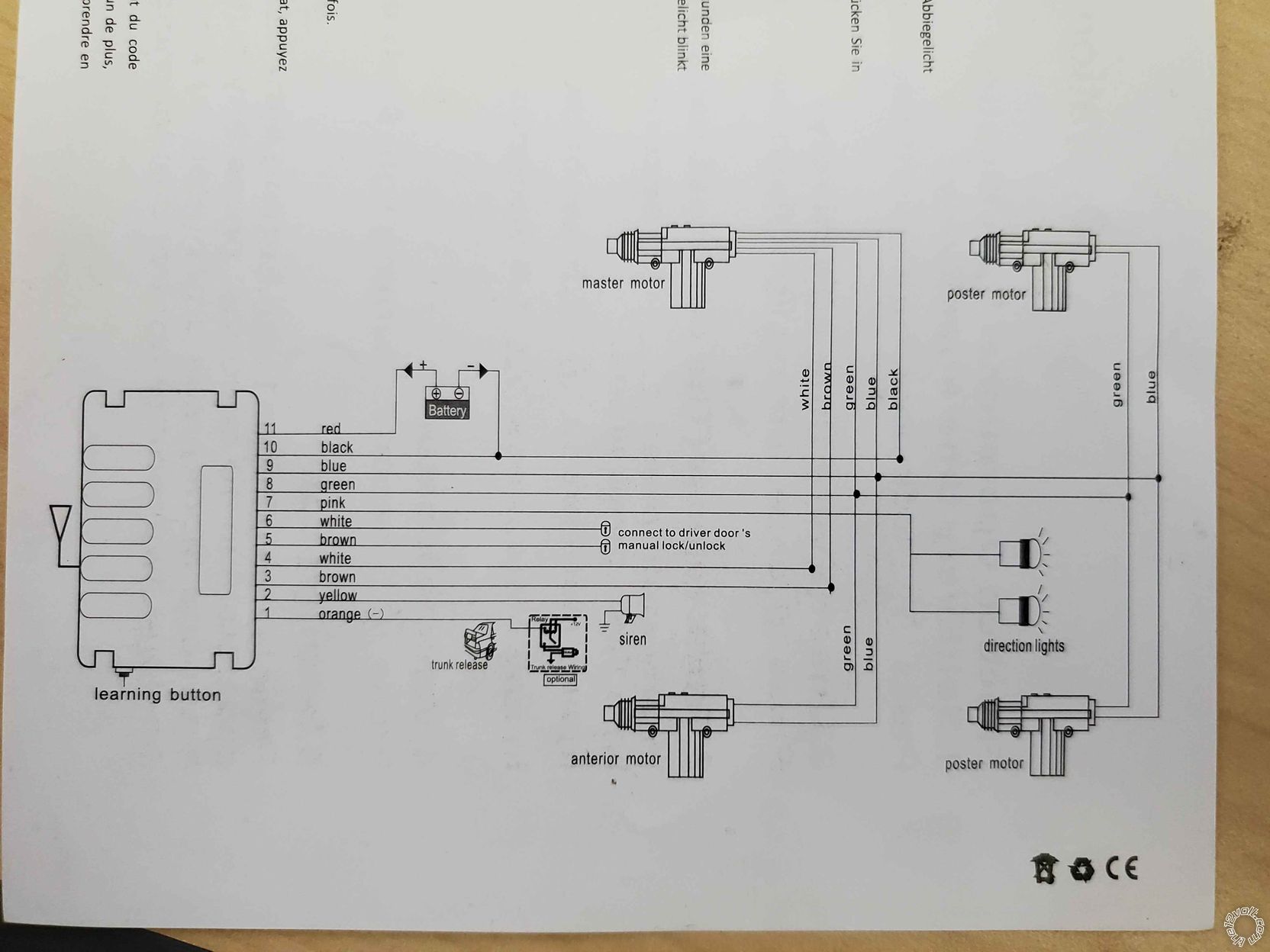
The "universal power lock kit" is very generic and doesn't seem to have a brand or model number. It's a 5-wire primary actuator system and I'm trying to utilize the brown and white wires that trigger a lock or unlock when grounded.
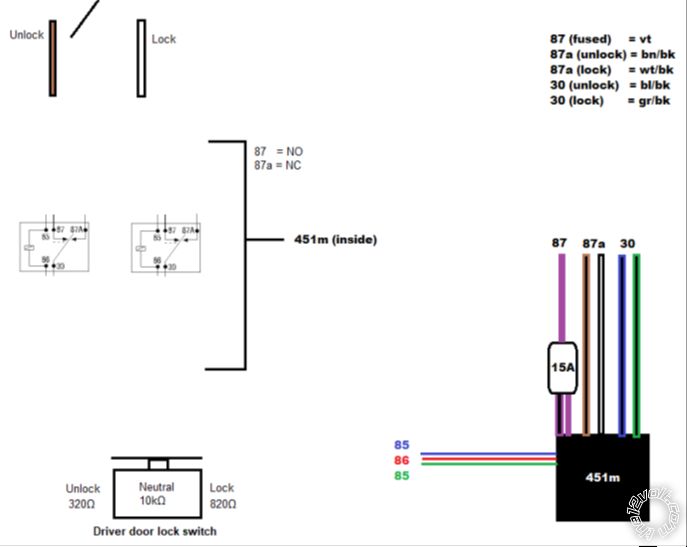
I also have a 451m relay on hand with a series of resistors that can be wired up if necessary.
Is it possible to use the one-wire from the power lock switch with what I have available to send ground to either white or brown wires in a logical way? This can be in either a multiplexed fashion, a straight "ground pulse", or dealer's choice - I just can't wrap my head around how to wire this up properly

As far as I can tell, the brown and white wires are hooked up to a relay in this lock module so when you apply ground to one, it "closes that wire and switches to the other wire." Hopefully that makes sense...
(I also made this little drawing for trying to map out what I want to do...)
I'm thinking you added keyless entry to a base model without power locks and you wanting to incorporate factory door lock switches?
The simplest solution I can think of would be to let the BCM do the conversion and use the actuator wires to trigger relays and use those to feed your lock/unlock wires.
If you do this, be sure to use a suppression diode across the relay coils.
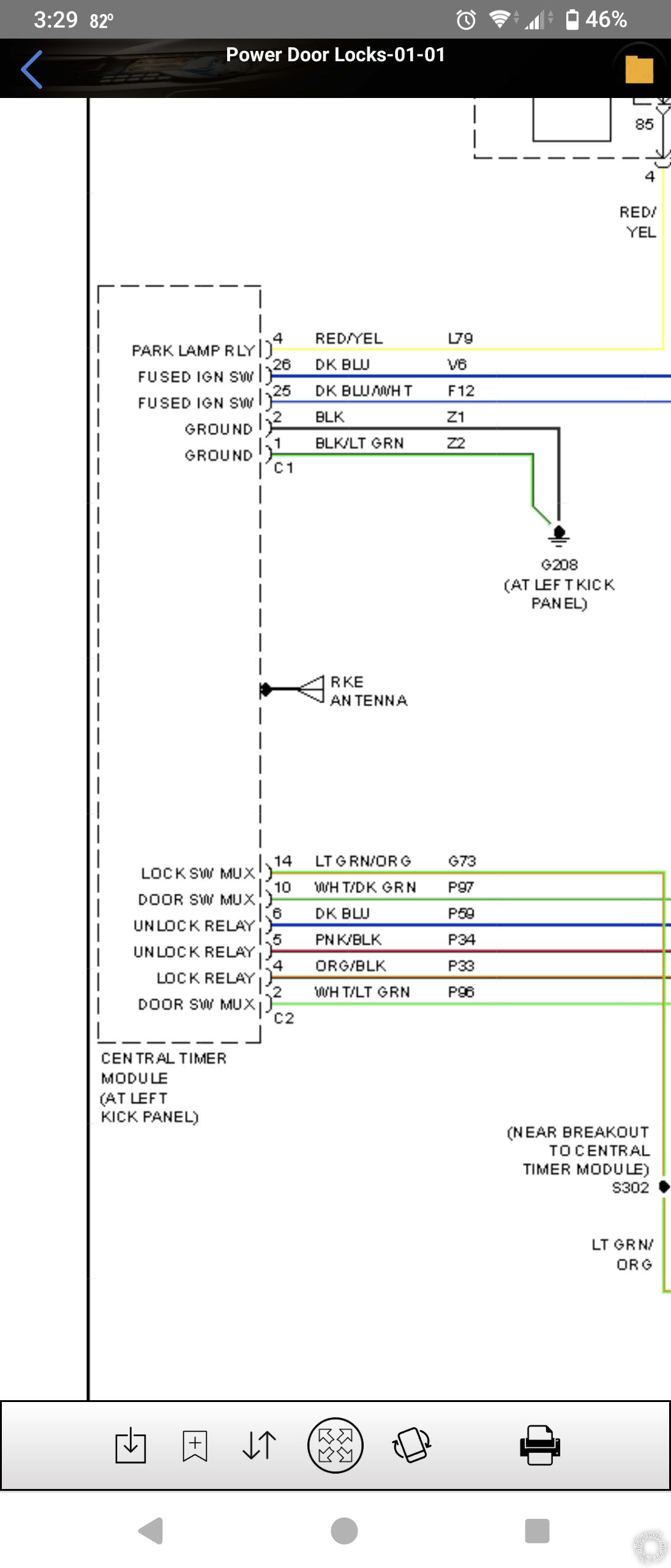
The actuator wires are connected to pins 4, 5 and 6:
Yes, this is a base model that never had power windows, power locks, or power anything. The CTM (BCM) is a base model so it doesn't have MUX capabilities. And yes, I am trying to use a factory door lock switch with the aftermarket module.
If I take the green/white wire that comes from the door lock (that would normally connect into the BCM) and touch that to either the white or brown wire from the aftermarket module, I can hit the switch and trigger the lock or unlock (depending on which wire I'm touching). As I mentioned previously, only one of the wires can be triggered at a time e.g., if the doors are locked, sending ground to the white wire doesn't do anything. Additionally, it doesn't matter which way the power lock switch is moved since it's just providing ground to the trigger wire.
I've also just found that the white lock and brown unlock trigger wires on the aftermarket module show 3.92V regardless of if the system is in a lock or unlock position....so that's a thing.
The closest I've come is applying 12v to the red wire (86) on the 451m, and then trying to find something that's switching ground with the aftermarket module (since it has an internal relay) in order to connect the green and blue (85) up. I've tried connecting the blue and green of the 451m to the blue and green wires of the RKE module running to the primary actuator in the driver's door. That either didn't provide a strong enough ground to to close 87 on the 451m or provide ground at all... I also attempted to use the white and brown wires running to the primary actuator as well (not to be confused with the white and brown white wires that I'm tryin to trigger on).
Since this is probably getting confusing, here's a wiring diagram that was provided with the cheap RKE kit:
Okay, that makes more sense.
Maybe an Arduino or Raspberry Pi? I would think you could use one of those for a solution. I've never used either so I couldn't help there. If you make friends with a robotics professor that might give you what you want.
An alternative would be to use an op amp (LM324 maybe). Basically a chip that looks for a voltage either above or below a reference voltage and when that happens gives you an output. Said output may need to be amplified to feed your input wires.