2005 Jeep Liberty, DEI 4806V With DEI 3100 Alarm?
5706V
Printed From: the12volt.com
Forum Name: Car Security and Convenience
Forum Discription: Car Alarms, Keyless Entries, Remote Starters, Immobilizer Bypasses, Sensors, Door Locks, Window Modules, Heated Mirrors, Heated Seats, etc.
URL: https://www.the12volt.com/installbay/forum_posts.asp?tid=148197
Printed Date: May 01, 2026 at 6:06 AM
Topic: 2005 Jeep Liberty, DEI 4806V With DEI 3100 Alarm?
5706V
Posted By: burntkat
Subject: 2005 Jeep Liberty, DEI 4806V With DEI 3100 Alarm?
5706V
Date Posted: October 31, 2024 at 12:36 PM
OK, looks like I may have bought the wrong unit- I bought a DEI 4806V, thinking it was a remote start WITH ALARM. Yes, I see now that it isn't.
I have an 05 Jeep KJ (Liberty in the US). ***MANUAL TRANSMISSION***. I have a DEI 3100 alarm as well. Is there a way I can combine these two systems to provide remote start and alarm functionality without having multiple keyfobs?
I already have the Jeep immobilizer type keyfob with the integrated remote and key. It's bulky and annoying.
I have a 556u immobilizer bypass module with a key inside it (already programmed the key and verified it cranks the car). Have not yet installed it. So I think that situation will be handled.
I want to have the 4 doors, rear hatch, hood, a shock sensor and (maybe) a field disturbance sensor. I understand I may have to gang some of these up on an aux input. I am fine with that.
I was going to use an Avital 4003 for Remote Start duties, but then it occurred to me this is an MT. I will use it in my son's AT-equipped XJ. It has wires for Factory Alarm disarm and arm (light green/black and green/white accordingly), which obviously could connect to the GWA wire for ARMED detection, and something else- maybe just a toggle on that wire via a relay. But, since it doesn't have a MTS mode, that's a no-go....
I admit, I bought on impulse, didn't do my homework on what I needed. So I have this Remote start (4806v) which will do MTS mode, now... and I need to either interface it with the 3100, or find an alarm that will interface with it...
Looking through the instructions on the 4806V, I see the Auxilary/Shutdown harness has a Green/Black on Pin 14, that is (Factory Alarm Disarm OUTPUT)... and a Green/white on Pin 24 (Factory Alarm ARM OUTPUT).. not sure these can interface with the 3100. Almost sure they can't.....
Anyone got some advice? I have to ditch the 4806V entirely... I have nowhere else I can use it. Is there a (preferably DEI) alarm that I can piggyback on the 4806V?
-------------
"Always listen to experts. They'll tell you what can't be done, and why. Then do it. - Robert A. Heinlein"
Replies:
Posted By: lee.lopez
Date Posted: October 31, 2024 at 12:57 PM
The 5706v is likely what you want. If I'm not mistaken the harnesses should be mostly the same, but the 5706v is also an alarm, so you'll just need to add some wiring and program.
Posted By: burntkat
Date Posted: October 31, 2024 at 3:15 PM
Thanks. I should have looked farther into this before I got the 4806. Ordered!
-------------
"Always listen to experts. They'll tell you what can't be done, and why. Then do it. - Robert A. Heinlein"
Posted By: burntkat
Date Posted: November 10, 2024 at 7:39 AM
OK, have received the 5706 and rewired what needed rewiring (ie, the 10-pin remote start harness in place of the 8-pin remote start harness from the 4806).
I have a few questions regarding the 5706 install. I used to install this stuff professionally, but it has been 35 years since that. I could figure it out myself, IF DEI still included full installation instructions with each unit, which of course they no longer do (opting instead to only include a quick reference, which is to gatekeep the information needed for their installers. Pretty shanky IMHO).
Should I start a new thread, since my questions aren't about the 4806 now?
-------------
"Always listen to experts. They'll tell you what can't be done, and why. Then do it. - Robert A. Heinlein"
Posted By: burntkat
Date Posted: November 10, 2024 at 11:09 AM
(Moderator apparently moved this over to this thread. Thank you, Mods....)
Please ignore all prior posts. I took the kind advice of that gent and bought the unit I should have gone with from the beginning...
Therefore......
I have a 5706v I am installing, have a few questions about the following...
I used to install professionally a LOOOONG time ago, but there also used to be complete documentation in each kit. Plus, they have gotten more complicated. So please be patient with me...
Vehicle - 2005 Jeep Liberty Renegade, 4x4, 3.7 v6 with 6-speed manual transmission
Alarm/Remote start - Viper 5706v, with 2 added 535T window rollup modules, 556U immobilizer bypass module, 456L door lock interface, and an Autolight light automation module (not DEI as I couldn't find one in stock. Does not interface with the alarm or remote start)
-MAIN HARNESS (6-pin connector)
difference between pin 4, white/brown 'parking light isolation wire (87a/NC of onboard relay)' and pin 5, white 'parking light output (30 Common of onboard relay)'. I get that these are relay terminals, but don't understand the need to have two separate wires doing basically the same job.
Pin 6 - GWA. Presumably for the alarm functionality, so it would control field sensors, window modules, etc.
-REMOTE START HARNESS (10-pin heavy gauge connector)
I believe I mostly understand what's going on here. However-
Pin 8 - Orange - + Accessory Output. So basically, a Positive when armed (or in this case, when remote started?). So this would go to the Ignition Accessory wire in the harness?
Pin 10 - + Ignition Input/Output. Presumably as above, but goes to an Ignition wire at the Ignition switch? Possibly doing double duty to detect Ignition draw for the alarm (and thus, an Input in that regard) as well as providing Ignition output to the Ignition harness for Remote Start? Am I on the right track with this one?
Not sure what to make of all the Flex Relay wires (Pins 2(pink/black),3(pink/white), and 9(red/white). I assume these are for odd vehicles like Toyota, where there are 'split ignition' circuits (where there are two or more separate circuits needing IGN while running, but the circuits are wired separately-ie, not applicable to my application.
That's enough for now. I will have more questions in a bit. I am actually installing this 'as we speak'.
-------------
"Always listen to experts. They'll tell you what can't be done, and why. Then do it. - Robert A. Heinlein"
Posted By: lee.lopez
Date Posted: November 10, 2024 at 1:21 PM
First, download the full manual from the download section of this site:
https://www.the12volt.com/installbay/file.asp?ID=1341
Main harness, the white/brown is not used in your case. Some older BMWs req'd interrupting a wire to turn on the parking lights.
GWA, basically, yes.
Remote start harness pin 8, no, the big orange wire provides positive accessory voltage to power the accessory circuit in the vehicle during remote start. You'll want this for HVAC functionality.
Pin 10, yes.
Flex wires, yes.
The full manual does a much better job of explaining so be sure to look it over.
Posted By: burntkat
Date Posted: November 10, 2024 at 1:45 PM
Thank you so much! That's already a huge help. All I found before was the quick start guide which came with the system.
So, looks like the pin 8 and 10 on the remote start harness both go to the Ign switch, hot when in ACCY and IGN, respectively
-------------
"Always listen to experts. They'll tell you what can't be done, and why. Then do it. - Robert A. Heinlein"
Posted By: burntkat
Date Posted: November 10, 2024 at 4:37 PM
OK, from that manual..... Regarding pin 10 (Pink, IGN 1 input/output):
(snip)
Pink: IGNITION INPUT/OUTPUT
This wire connects to the main Ignition circuit in the vehicle. It will supply voltage to the Ignition circuit in the
vehicle during the remote start sequence and is also the Ignition input to the unit while the remote start is NOT
activated.
(/snip)
(emphasis in BOLD is mine)
I have located a wire in the harness (pink/lt.green) coming from the ignition switch, which exhibits the following behavior (confirmed by computer-safe test light):
0 volts @ rest (ie, no key, IGN off)
0 volts @ key in ignition (so, not KEYSAFE wire)
12 volts @ ACCESSORY and while cranking/running
So basically any condition other than ignition switch off, it has power.
What concerns me is the manual says the system will supply current via the PINK wire: "It will supply voltage to the Ignition circuit in the
vehicle during the remote start sequence and is also the Ignition input to the unit while the remote start is NOT
activated."
I am pretty sure this is a misprint. Why would it provide voltage to the IGN circuit while the RS is NOT activated?
Also, need clarification -"... during the remote start sequence... "- is this during the starting portion only of the remote start, or during the entirety of the Remote Start run cycle (so 12 minutes or more)?
(EDIT TO ADD: OOOOOHHH, now I get it. The RS uses that wire to supply IGN output to the vehicle while it's running the car without KII (key in IGN)... And when the car isn't running, it's using that line to provide 1l2 v+ to the RS unit (brain). So I am still confused. If it wants to get voltage for the unit while the car isn't running... It needs a constant 12v supply, not Ignition. Still unclear. Research to be done. Good time for it, as it's now dark and I am cleaning up via headlight.
I now have the 6-pin harness completely wired, and the 10-pin completely wired (save for the unneeded Flex Relay and this Pink wire). Thus my asking.
I was able to spare back (cut short and heatshrink) a lot of the wires on the 24-pin harness. I only need about 8 more of them connected. NOT looking forward to getting the doors connected, nor the windows. I havent messed with windows in years other than replacing regulators. I have no idea what kind of switch system Chrysler put in this thing.
-------------
"Always listen to experts. They'll tell you what can't be done, and why. Then do it. - Robert A. Heinlein"
Posted By: lee.lopez
Date Posted: November 10, 2024 at 7:33 PM
The pink wire connects to the ignition wire (pink/light green) at the ignition harness. When not remote started, it's an input for programming (key on, key off, hold down button, etc.). It also serves as an input to trigger the alarm while it's armed. If the alarm is not disarmed and you try to start with the key, the alarm will trigger.
Posted By: burntkat
Date Posted: November 10, 2024 at 9:48 PM
Thank you, sir, makes sense now.
-------------
"Always listen to experts. They'll tell you what can't be done, and why. Then do it. - Robert A. Heinlein"
Posted By: burntkat
Date Posted: November 11, 2024 at 7:32 PM
HUGE, HUGE, HUGE thanks to the above folks that have posted. You've set me on the right path. Just wish I'd come here BEFORE buying a $200 RS/KE system I have utterly no use for as none of my vehicles came with more than an immobilizer.
-------------
"Always listen to experts. They'll tell you what can't be done, and why. Then do it. - Robert A. Heinlein"
Posted By: burntkat
Date Posted: November 14, 2024 at 8:54 PM
I want to add a blinking dash LED a'la oldschool car alarms, center of the dash....
Obviously this would come off the GWA output. is there a specific LED I need so it's not just solid-on?
I miss the old alarms that had a simple plug-in LED. I know this can't be too difficult. The Control Center LED isn't cutting it as a deterrent. I may also work these into the parking lights, not sure.
-------------
"Always listen to experts. They'll tell you what can't be done, and why. Then do it. - Robert A. Heinlein"
Posted By: lee.lopez
Date Posted: November 15, 2024 at 4:19 AM
This thread links to a related tech tip: https://www.the12volt.com/installbay/forum_posts.asp?tid=143843
While in theory you could use a relay to add parking lights, this is definitely not recommended as it would draw down the battery significantly quicker.
Posted By: burntkat
Date Posted: November 15, 2024 at 8:49 AM
Hey, thanks for replying!
I get what you're saying, but I must not have stated my idea properly.
I was thinking about adding a small LED to the parking light enclosures, and blinking that.
Though, on second thought, it would probably attract extra attention.
-off to check the link you posted, now-
-------------
"Always listen to experts. They'll tell you what can't be done, and why. Then do it. - Robert A. Heinlein"
Posted By: burntkat
Date Posted: November 23, 2024 at 5:09 PM
Had some delays on this. It's about 3/4 installed, lots of other issues slowing me down. Couldbt find relays, had to order more. Likewise computer-save test light, etc... And then everyone and the dog was sick last weekend. Excuses, excuses...
Back at it now. About 10 more connections to make, half of which involve relays.
I can manage the relays, they're easy.
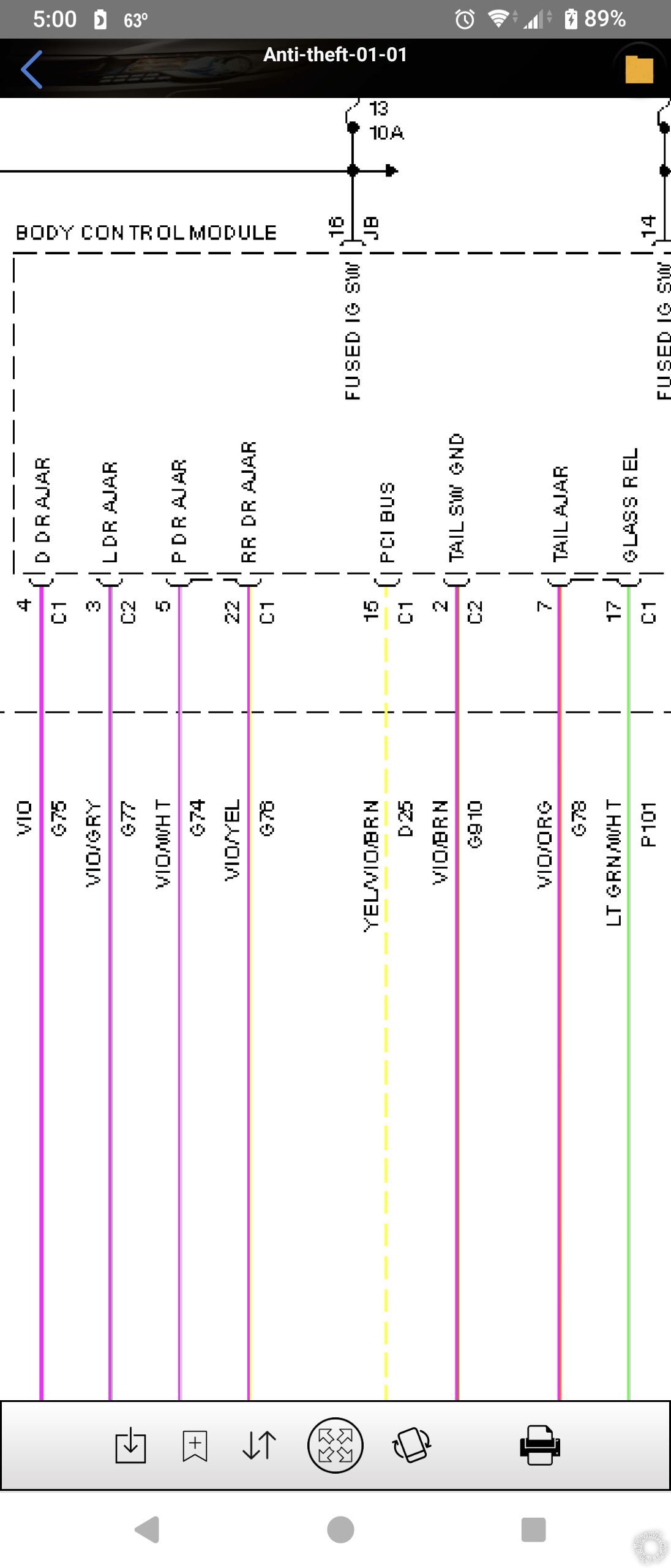
I am to the point of needing to wire in the doors. There's 4 doors, into one trigger. Obviously they need to be diode-isolated. Easy enough. But the wires are giving me fits finding them. All my sources say they are at the BCM on various connectors. I'd rather just go to the wire in the harness. Surely it has to be in the footwell somewhere.
My source says they are tan w/opt.stripe (ex- drivers is tan, pass is tan/white, another is tan/black,and there's another tan/w stripe as well. Well.....where?
-------------
"Always listen to experts. They'll tell you what can't be done, and why. Then do it. - Robert A. Heinlein"
Posted By: lee.lopez
Date Posted: November 23, 2024 at 7:32 PM
Look for purple wires for the door triggers.
I remember as an installer (decades ago) I used to go to the dome light often for door triggers. However manufacturers started making them fade out which could cause issues with the alarm. Some installers would relay isolate, which would solve one problem but they would chatter extremely loud on the fade out. The solution was to either diode isolate each door trigger individually, or use a transistor instead of a relay at the dome light to interface with the alarm.
Posted By: burntkat
Date Posted: November 24, 2024 at 4:25 PM
Purple? I will keep that in mind.
These should be NO triggers on the doors, I assume? I know there is no pinswitch, instead it is built into the door locking mechanism itself. So presumably shows a ground when a door is open.
Couple that with a need to diode isolate each of the 4 doors, I'm looking at 4 pieces of wire connecting to the alarm door trigger, each having a diode with proper orientation to ground and each of the ends of those wires going to a door trigger in the harness
-------------
"Always listen to experts. They'll tell you what can't be done, and why. Then do it. - Robert A. Heinlein"
Posted By: lee.lopez
Date Posted: November 25, 2024 at 5:01 AM
Posted By: burntkat
Date Posted: December 01, 2024 at 10:42 PM
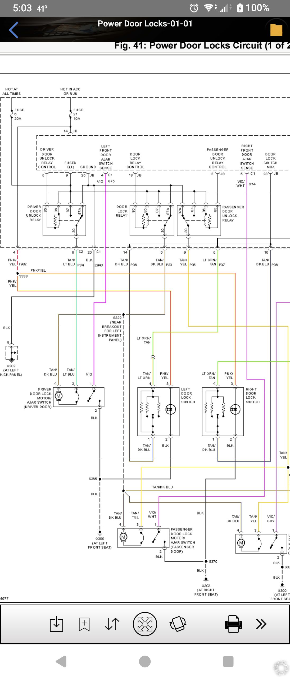
How about driver's door priority unlock?
If I am looking at it properly, there's one wire for all the doors, lock or unlock. A different resistance is provided to trigger lock or unlock.
Factory has driver's door priority unlock. But I won't be using the factory fob....
-------------
"Always listen to experts. They'll tell you what can't be done, and why. Then do it. - Robert A. Heinlein"
Posted By: lee.lopez
Date Posted: December 02, 2024 at 5:30 AM
There is a separate relay for driver's door unlock. If you can identify which relay this is at the back of the BCM you can pulse a ground to 85. Since this circuit is inside the BCM, the easiest way to do this is probably soldering a wire directly to terminal 85 on the relay.
Otherwise just relay isolate the tan/light blue wire for the driver's door lock actuator. You can get this wire at the BCM, connector 2, pin 8. Cut this wire and connect terminal 87a to the BCM side, terminal 30 to the actuator side. Connect terminals 86 and 87 to a fused positive 12 volt source. Terminal 85 will be your negative trigger.
Posted By: burntkat
Date Posted: December 05, 2024 at 9:41 PM
Wow that's helpful!
Where are you getting this info and the diagrams?
-------------
"Always listen to experts. They'll tell you what can't be done, and why. Then do it. - Robert A. Heinlein"
Posted By: lee.lopez
Date Posted: December 06, 2024 at 7:52 AM
PM sent
|