I recently purchased a 2012 Chevy Impala LT from a private party and they didn't have the factory key fob, and instead of paying the dealership $300+ for the fob and programming I decided to install a remote start that I had from a previous car which would end up costing less, and allow me to start/lock/unlock the car from farther away.
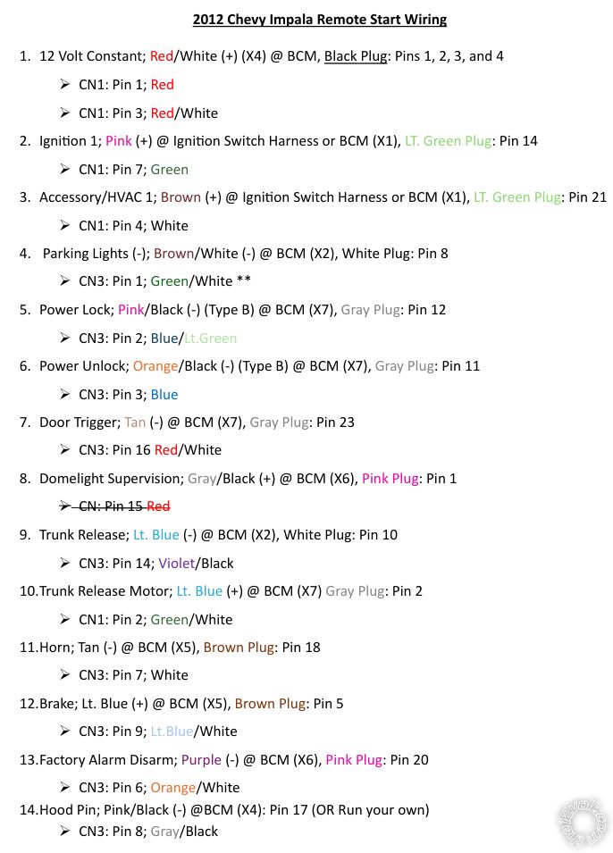
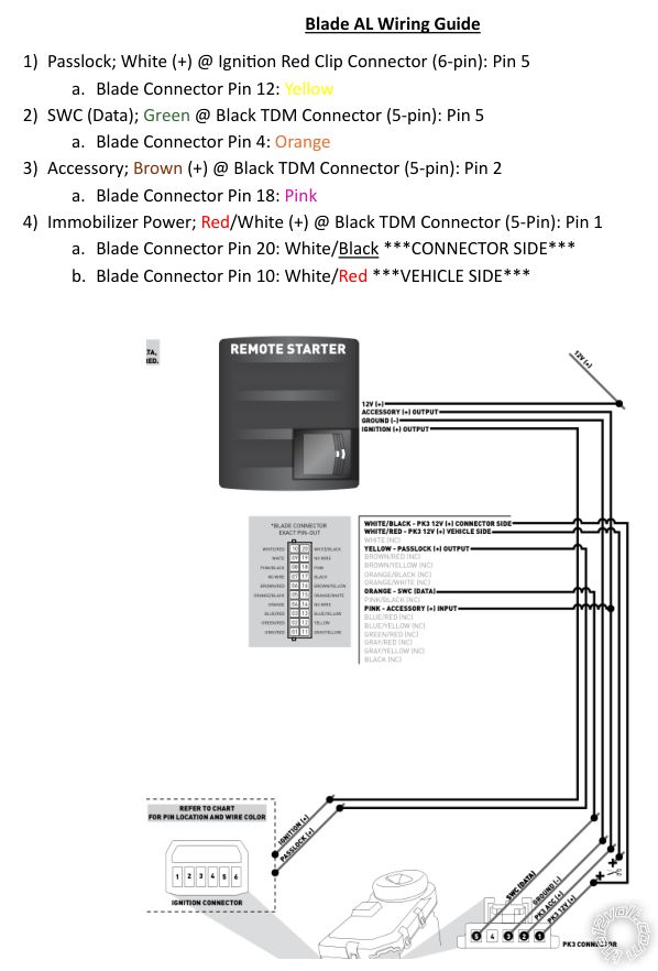
The remote start model is the Compustar CM900AS with the iDatalink Blade-AL immobilizer bypass. I have already successfully installed the system and the remote start/lock/unlock are all functioning as they should. All of the wire splices I made are detailed in the photos attached. The reason I am coming here for advice is I would like to connect the Rear Defroster as one of the Auxiliary Outputs and I am unsure of what the best way to proceed is. The wire I would be tapping into is in the HVAC X1 connector, Pin 8, White wire with positive polarity. This wire powers the Rear Defrost/Defog relay. I have the choice between 2 wires to use, unless someone who knows more about this can teach me otherwise.
Option 1: Pin 5 (Blue) on the CN1 connector. It provides 12V+ output that powers up during the remote start, and it is programmable to a positive (+) accessory output by moving the jumper.
Option 2: Pin 4 (Black) on the CN3 connector. It provides a ground while running, 250mA latched negative (-) output. It stays on until the remote start is turned off.
Option 1 initially seemed like the way to go since the polarity is correct and seems straight forward. However, the Compustar manual says the wire is programmable to be either a 2nd Ignition, 2nd Starter, or an Accessory output. It doesn't specifically say it has the additional 18 programmable outputs like the majority of the CN3 wires. If I go with this one I think the Rear Defroster will get power every time a remote start the car. I don't know how bad that would be but it seems less than ideal.
Option 2 would involve wiring a relay in to have the ground trigger positive voltage to the rear defog/defrost relay which I haven't done before but there's plenty of information available about it. The reason this wire might be easier though is it is a latched output, and Compustar manual says it has 18 other programmable outputs, which is where you can set temperature requirements for it to power on.
I don't have access to Firsttech's website which I would imagine has the exact instructions on the correct way to do all of this so I was hoping someone might have some insight into what the best way to go would be. If there is a better way of doing this I would love to hear it as well. I have attached pictures of the wire connections that I have made. If providing the CM900AS manual is helpful I would be happy to do so.
If you haven't yet, download the full manual:
https://www.the12volt.com/installbay/file.asp?ID=1428
If you have an OP500, you can change one of the POCs to defrost. If you don't, you can have a local shop assign one for you. You can adjust what temperature it triggers and how long it latches. It'll give you a negative output which you can use to trigger a relay to convert to positive.
Of course if you don't want to you could just use the second accessory like you mentioned. Then it'd just be on any time it's remote started.
Thank you for the suggestion, I did find an updated manual (v1.29) which is from 2022. I have the ADS Weblink Cable so I can connect it to my computer and set the programming options/update firmware, I'm assuming that's the same thing as the OP500 can do but it probably doesn't need to be removed from the car?
I think wiring in the relay is the way to go then, and use the Black (Pin 4) wire to make the connection. I don't know how "bad" it would be to have the defrost run every time the car is remote started but I can't imagine it being a good thing over time, especially in the summer.
If I am using the Black wire, which is providing a latched negative (-) output that stays on throughout the remote start, that is essentially a constant output, so I would be using the "
Convert a Negative Output to a Positive Output Relay Wiring Diagram" to connect it to the defrost wire right? Thank you for any input you can provide, I haven't wired a relay into a car before and would hate to make an error at this point when everything else is working correctly.
The OP500 is a handheld programmer that must be used to change certain features that can't be changed with the flash cable.
Yes, use the relay diagram you referenced. You should consider installing a diode across the relay's coil, too. This will extend the life of not only the relay, but also the Compustar.
To do so, connect the striped side to the coil terminal you connect to constant voltage and connect the other side to the remaining coil terminal.