multiple led & starter kill circuit wirin
Printed From: the12volt.com
Forum Name: Car Security and Convenience
Forum Discription: Car Alarms, Keyless Entries, Remote Starters, Immobilizer Bypasses, Sensors, Door Locks, Window Modules, Heated Mirrors, Heated Seats, etc.
URL: https://www.the12volt.com/installbay/forum_posts.asp?tid=23362
Printed Date: May 10, 2026 at 8:16 PM
Topic: multiple led & starter kill circuit wirin
Posted By: crosswired
Subject: multiple led & starter kill circuit wirin
Date Posted: December 26, 2003 at 3:40 AM
hey folks, hope your holidays went (are going) well. gotta quick one for you. ive searched and feel pretty confident, but want confirmation. i am gonna hook up 3 extra leds and a scanner. im not conversant enough with diodes to use them (stick with what you know, right). i am planning to run a relay for the neg output from the alarm (as a distribution center). from its output, i will hook up two more relays: the starter kill relay, and a relay for the Varads. (all leds are the 3 wire [pos, grd, -output when armed] variety.). (the output of the starter kill wire is 500ma. im fairly sure that it can support triggering two relays, but im insanely anal, so i figured a "distribution relay" would remove any doubts). i dont mind using an extra 2 buck bosch relay. |--starter kill relay orange output from alarm (500ma)------distribution relay----| |-- led relay sorry, i can't draw diagrams too well on a computer or in this forum. LOL. sound good? no need for blocking diodes (other than the existing one in the starter kill socket), etc like this, right? i figure all the Varads wiring will be tied together anyhow, and the relays isolate any feedback problems (from led's to starter kill, etc), no? i really appreciate any and all help (telling me im nuts, or that it sounds good). im open to other ideas as well (like i said, i [try to] do what i know). many thanks in advance. :)
Replies:
Posted By: xetmes
Date Posted: December 26, 2003 at 9:23 AM
you are going to have 3 relays on while the vehicle is off? I would stronly advise not to, that is over .3 A of a draw...
Posted By: Teken
Date Posted: December 26, 2003 at 12:35 PM
https://www.the12volt.com/installbay/forum_posts.asp?tid=22821&PN=6
Perhaps you could take the time to read over the thread above and it might answer any questions you have.
Also, I agree with Xetmes with regards to the current draw. A 300 mA would present a very high parasitic current drain on the vehicles battery.
The threshold for most vehicles is 50-60 mA per hour. In your case the vehicles battery would be depleted in 48-72 hours depending upon weather conditions.
Dead Battery = Dead alarm.
Regards
EVIL Teken . . .
Posted By: crosswired
Date Posted: December 27, 2003 at 9:03 AM
xetmes and Teken, thank you for your responses. i have always been unclear on just how much power a relay's coils draw (always read 50-200ma). that was why i was unclear if i could power two relays off of the starter kill output (500ma max). i was not feelin great about having the power draw of 3 relays, either. the alarm is only on for a very max of 13 hours at a time (only when the g/f is at work). Evil, i had read that thread when i was researching this topic (i read about 20-30 threads). Hamilton's response in that thread was actually what made me think i would be ok doing what i suggested. (without the third relay though). i am still unclear on how i would utilize diodes on this (even after reading the other thread). i had the same question as digger did (halfway down other thread) about what you said (is his interpretation correct? i understand what he is saying. i think your diagram confused me [not hard to do). LOL] i would create a "Y" wire from the orange alarm neg output wire. place a diode on each leg of the Y, and then run one leg of the Y to the starter kill relay and the other leg to the leds??? BTW, the three leds draw 20ma each, and im not sure what the scanner will draw. sounds like a relay will draw less juice than powering the led's alone, no? so if i do two relays (like i originally thought, but without the distribution relay), that would work? i wont overdraw the 500 ma output of the ground output? any diodes needed for this? i really appreciate the input. you guys rock.. hope your holidays went well!
Posted By: serialthrlla
Date Posted: December 27, 2003 at 10:04 AM
it was always my understanding that a relay used 150ma of draw
Posted By: Teken
Date Posted: December 27, 2003 at 11:34 AM
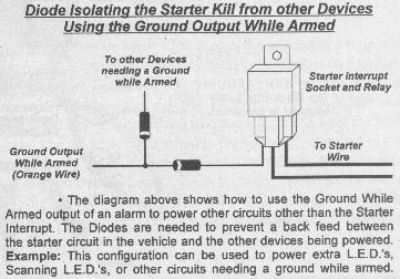
671_Diodes4.jpg
If you follow the image file I have provided above. Then you will require only (1) relay which already is present.
It is the most direct and simple approach. I always suggest this route as it is so simple in integration and planning.
As you have been made aware, power is what we need at all times to protect our pride and joy.
Using this simple and direct approach will ensure the current drain is as low as possible.
There are many other ways to do this, but for those in a pinch, this is the most direct approach with the on hand parts already installed
ie. Existing Starter Kill Relay
Regards
EVIL Teken . . .
Posted By: Teken
Date Posted: December 27, 2003 at 11:52 AM
serialthrlla wrote:
it was always my understanding that a relay used 150ma of draw
It would be fair to say that is the norm for a stardard SPDT Bosch relay. But the current draw is dependant upon the field coils resistance, which vary from 76-120 ohms.
As I have pre-measured the 350 lot bag of Bosch relays in my service bag, they have a coil resistance of 83.4 ohms.
12 VDC / 83.4 ohms = 140 mA
That is why all installers should take all these little things into account for the long term use. When parasitic current draw is a concern, taking the time and resources to implement a higher resistance coil with a 120 ohms is the difference of 50 mA .
That is the difference *dependant upon battery capacity* of a battery lasting 12 hours or 72 .
Regards
EVIL Teken . . .
Posted By: Teken
Date Posted: December 27, 2003 at 12:46 PM
crosswired wrote:
BTW, the three leds draw 20ma each, and im not sure what the scanner will draw.
The 20 mA is based on a *constant* ON state. Not when it is simply flashing away. It is more like 8-12 mA while flashing away.
Regardless of that fact, you should always use the maximum value anyways to ensure enough head room, or fudge factor is allowed.
Waking up ifirst thing in the AM to go to work, and only to find that the vehicle is completely dead is almost like being around a gurl with PMS.
  
Posted By: crosswired
Date Posted: December 27, 2003 at 2:07 PM
thank you guys so much for the education. Teken, that diagram made it all clear (i suck at visualizing, but pics are great). i like the part about measuring what the coil draws. do you use a VOM across the coil terminals (85 and 86)? i did this and it read 80.7 ohms. im guessing this is what you do (ive never known to do that). so i have 3 led's *20ma/each and a scanner (i havent gotten it yet-dont know what it draws, but id guess around maybe 100ma (9 leds). this sound plausable? should i wire it like the diagram [Teken] attached, or should i use a relay for the leds? im still not sure on the numbers. (id wait to get the scanner so i can crunch some numbers, though i thought you might have a good idea. im still afraid of overloading the 500ma meg output). i tend to be very cautious when i dont know what im doing. LOL. i hear you on the dead battery stuff. like i said, the alarm is not on except for when she is at work (up to 13 hours). then it is driven. i would feel real confident about using only the diode (like the diagram) for the three leds, just not sure about the scanner (never had one). im really afraid of frying that circuit. thank you all very much again. i really appreciate it and have learned a ton.
Posted By: Teken
Date Posted: December 27, 2003 at 2:41 PM
crosswired wrote:
do you use a VOM across the coil terminals (85 and 86)?
Exactly, just like that.
crosswired wrote:
i did this and it read 80.7 ohms.
12 VDC / 80.7 coil resistance = 150 mA typical current draw for a relay.
crosswired wrote:
]i havent gotten it yet-dont know what it draws, but id guess around maybe 100ma (9 leds). this sound plausable?
All you need to do to find out the *actual* current draw from the scanner, is to place your DMM in series of the LED scanner.
You will take the negative (-) lead from the scanner, and place your DMM's negative probe inline (series) with it. Then on the other end of the scanners (+) positive lead you will go to power.
You will of course, have to ground the third trigger wire too, to activate the scanner LED.
crosswired wrote:
im still afraid of overloading the 500ma meg output). i tend to be very cautious when i dont know what im doing. LOL.
You will not over load the alarms negative output. As the current is being provided by the 20 /30 /40 amp relay.
BTW: You are doing just fine . . .
Regards
EVIL Teken . . .
Posted By: crosswired
Date Posted: December 27, 2003 at 6:13 PM
 Teken, thank you very much for the info. i will do that if the scanner ever gets delivered. :-) Teken, thank you very much for the info. i will do that if the scanner ever gets delivered. :-)
im gonna be sidetracked by a new problem. stuck an old pioneer cd player in the car. now the deck goes on by itself after a few mins (part of the keep alive stuff on that car [94 camaro]. i.e., the radio, windows, etc stay functioning after key removal til the door opens and closes). real PITA. if i open the door, it kills the deck (just the opposite of how it should work). im sure i wired the deck right (only done ~ 100 decks). and if i had gotten the ig 12+ and memory backwards, id lose presets, time, etc each time i killed the ignition. the whole memory retention thing on the car is funky and doesnt work as it should (per the owners manual). gonna just run a new key-on wire if i can find a circuit that isnt part of the memory retention circuitry (dont know if the BCM is on the way out). always nice to create new problems for yourself. i really do appreciate all the help you have given me. BTW, you were talking about leds, relays and stuff killin a battery off while you're gone. i think having the radio blasting tunes all night would do it. LOL.....
|