Ok first here is all the instructions I was given.
I was also given some informationa bout where wires are in my care which is.
Wiring Colors and Notes |
Function | | Vehicle Color | Location |
Start: | | BLACK/ WHITE | IGNITION SWITCH HARNESS |
Ignition #1: | | BLACK/ RED | IGNITION SWITCH HARNESS |
Ignition #2: | | BLACK / YELLOW OR | BLUE / YELLOW - IGNITION SWITCH HARNESS |
Ignition #3: | | N/A | |
Accessory: | | BLUE/RED | IGNITION SWITCH HARNESS |
Brake Light: | | GREEN / WHITE (+) | AT SWITCH ABOVE BRAKE PEDAL |
Tach Signal: | | BLACK / YELLOW ('#) OR | BLACK - IGNITION MODULE OR DASH TACH |
Parking Lights: | | GREEN | (+) AT FUSE BOX |
Headlights: | | | |
OEM Alarm Disarm: | | | |
OEM Alarm Arm: | | | |
Diesel Glow Plug: | | | |
Clutch Bypass Wire: | | | |
Notes: | | |
Alarm and Keyless Entry Wiring Colors and Notes |
Function | | Vehicle Color | Location |
Constant +12 Volts: | | WHITE/ RED OR WHITE | IGNITION SWITCH HARNESS |
Starter Kill: | | BLACK/ WHITE | IGNITION SWITCH HARNESS |
Ignition +12 Volts: | | BLACK/ RED | IGNITION SWITCH HARNESS |
Dome Lights/Superv: | | RED / WHITE | (-) REAR PIN SWITCH OR AT RELAY |
OEM Horn: | | GREEN/ RED (-) | STEERING COLUMN HARNESS |
Power Lock: | | RED | DRIVER'S KICK PANEL * |
Power Unlock: | | GREEN | DIRVER'S KICK PANEL * |
Trunk Release: | | | |
Alarm Input Wire: | | RED / WHITE | (-) REAR PIN SWITCH OR AT RELAY |
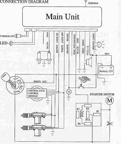
Now I got the battery to the red wire on the alarm harness but I am so stumped about splicing it off to the brake pedal then the oragne one splices into that then hooks up to the circle with the X then that goes to the ground and am I supposd to wire the positive directly to the little nub on the ignition thing where they are all hooked on or can I splice it into that wire some how. And what wires are already there and what ones do I have to wire? Like the ones to the power locking system. I thought this was going to be as easy as installing a car stereo but I was dead wrong.
Thanks for any help. This is a great site you guys got going.
This is more difficult then a stereo for sure. From what Im seeing it wants you to hook the orange brake wire from your unit to the neg side of the brake switch. Use your meter here to find which wire does not get 12 volts. You will see the switch mounted on the brake pedal. Dont worry about all that circle with the x and little nub on ignition thing. Thats just showing you the circuit.
The door locks should be easy cause you just have a neg door lock system and the diagram is indicating you have on board relays. So you would just hook the brown lock wire from the unit to the red power lock wire found in the driver kick panel. The white unlock wire would then go to the green unlock wire in the driver kick panel.
Sorry I haven't replied but I haven't been able to work on it since it's been about 33 degrees and snowing and all I have is a open carport. This weekend isn't looking good wither since the high on sunday is supposed to be about 28. I need a friend with a heated shop. I did figure out that I don't need to have the power to the brake and to ignition. Thats just so it can learn new remotes which I don't need it to. I have located most of the wires its just a matter of squirming my hands up there and fishing them out.
Oh I see. Thanks for letting me know. At the beginning I was wondering why an alarm was using the brake pedal. Remote start will use it to reset it but, I didnt know what an alarm needed it for. Good luck on the install