What is the ground output while armed(-) wire on an alarm? I have heard it is the orange wire but my alarm says the orange wire is an optional circuit defeat output (-). Are these the same?
I am wondering this b/c I want to install a starter disable and some extra led's and found this diagram which supposedly works for it.
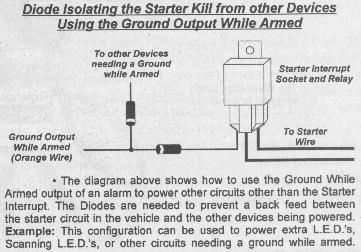
https://www.the12volt.com/installbay/uploads/671_Diodes4.jpg
The only other question I have is do you need an actual starter interrupt unit or just a relay? In this picture is that just meant to be a relay or some other unit? What goes where on the relay?
Thanks
Ya the ground when armed and optional circuit defeat output (-) are the same. Here is how to wire the relay for the starter kill. You just need the relay https://www.the12volt.com/relays/page2.asp
burnerofhells wrote:
What is the ground output while armed(-) wire on an alarm?
This provides a constant ground source ONLY when the alarm is activated / armed.
ie. To enable a starter kill relay, to roll up a window.
burnerofhells wrote:
The only other question I have is do you need an actual starter unit or just a relay?
That is dependant on the alarm CPU's negative current output, and the current supply draw required.
If you are adding only a few more LEDS on to the system then that is fine. If you need more current, then you will need to install another relay to boost up the negative current source.
Regards
EVIL Teken . . .
Ok, I think i understand most of it now. I will probably only be adding one more led. What size diodes do i need to use? What size relay?
Maybe if all I want is 2 leds and one is directly hooked up to the brain already, there is a better way to hook up another led than this diagram since the diagram method allows many leds to be hooked up.
When hooking the leds up to this circuit i hook the (-) ground (of the led) up to the circuit and the (+) up to a power source, correct?
How do i wire up the relay?
If you are simply adding (1) more LED, you can simply connect it to the alarms LED circuit wiring, using a resistor in series.
No need for a diode, relay, or anything. A LED is a form of a diode.
You will simply wire the LED with respect to proper polarity. As it is in your alarm system.
A brand new LED will have two leads, one of which is longer than the other. The longer one is the (+) anode the shorter lead is the (-) cathode.
If you make a mistake and cut the leads off and they look both the same, simply look into the LED.
Once again the side that is thinner then the other is the (+) Anode / Positive side, the other thicker one is the (-) cathode / negative side.
If your alarm is a Viper unit you do not need to install a resisitor. If you are unsure as to the voltage output of your alarms LED. Then be safe and place a 470 ohm resistor in series with the LED.
If the LED appears very dim, and you do not have a DMM to varify the voltage. At that point it is pretty safe to say that the alarms LED output is around 2 volts, and you can remove the resistor to restore the full light output of the LED..
Regards
EVIL Teken
burnerofhells wrote:
Ok, I think i understand most of it now.
I think alot of people have missed the whole point of this alarm output, and its overall function.
The *ground while armed* output from the alarm system is used to turn *ON* something, while the vehicle is off.
If you simply wired the LED or any other device to a constant or *unswitched* power source the device would be on at all times, regardless of the vehicles operational status.
In the picture that I provided above, its intent is to provide a ground, such as that for a scanner LED, or any device which you require the device / unit to be turned *ON* after arming the alarm.
ie. Window roll up, LED Scanner, etc.
I hope that clarifies the use of the *ground while armed circuit*
Regards
EVIL Teken . . .