Keyless entry on a 93 Ford Tempo
Printed From: the12volt.com
Forum Name: Car Security and Convenience
Forum Discription: Car Alarms, Keyless Entries, Remote Starters, Immobilizer Bypasses, Sensors, Door Locks, Window Modules, Heated Mirrors, Heated Seats, etc.
URL: https://www.the12volt.com/installbay/forum_posts.asp?tid=2400
Printed Date: April 08, 2026 at 1:38 AM
Topic: Keyless entry on a 93 Ford Tempo
Posted By: snes_83
Subject: Keyless entry on a 93 Ford Tempo
Date Posted: July 31, 2002 at 8:58 PM
Hi, could someone please help me with my 93 Ford Tempo keyless entry installation? I am having trouble getting the lock / unlock to work with my Omega REC-11 keyless entry. I also have 4 bosch relays available. I think that I have "5 Wire Alternating (+) 12 V DC" I'm pretty sure that the pink/green wire is lock, and the pink / YELLOW wire is unlock. This is how I currently have it wired:
 On each switch, 1 wire is constant 12 V, one is the unlock wire, the other is the lock wire, and 2 are ground wires. I have tried hooking it up many ways, but the relays just make clicking noises, and nothing happens. PLEASE PLEASE PLEASE help!! I have already spent a whole weekend trying to get this working. ****Whoever helps me the most to get this work, I will give $20.00 using PayPal.**** (no lie) -Tom
Replies:
Posted By: Velocity Motors
Date Posted: August 01, 2002 at 1:06 AM
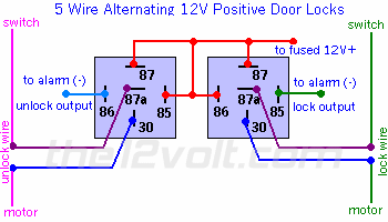
Your car has a (+) type door lck system. If your alarm has alternatinf polarity door lock wires, then hook straight up to the alarm otherwise you will need this diagram to hook up the door locks to reverse the (-) signal from the alarm: https://www.the12volt.com/doorlocks/page3.asp#3wp ------------- Jeff
Velocity Custom Home Theater
Mobile Audio/Video Specialist
Morden, Manitoba CANADA
Posted By: snes_83
Date Posted: August 02, 2002 at 11:40 AM
Ok, I couldn't get it to work with the information that you gave me. Here are some more details about my installation: On each door switch, I have 5 wires. The pink/green wire rests at ground and shows 12 V positive when I hit the lock buttton. The pink / YELLOW wire rests at ground and shows 12 V positive when I hit the unlock button. There are also 2 ground wires and 1 constant 12 V wire on each switch. My keyless entry system has negitive lock and negative unlock outputs. When I tried hooking it up using the diagram you gave me, I got a high pitched squealy noise from the relays, and it didn't work. When I tried hooking it up straight to the keyless entry system, it did nothing. I have also tried hooking it up as "5 wire alternating 12V positive door locks" with no luck. (maybe I'm hooking it up wrong???) One more question.... What is "the optional DLS"?? In my manual, it recommends that I use this, and it also says that "some doorlock systems, however, require more than the 500ma ground output that the keyless entry system's control module can accomodate". So do I need to get one of these or not? I don't know what this "DLS" thing really does... Whover replys next, could you give me some extra details?? This is my first time installing one of these, and this message board and my instruction manual assume that I know what I'm doing (and I don't) That $20.00 offer on PayPal still stands if anyone can help me get this working.....
Posted By: snes_83
Date Posted: August 02, 2002 at 1:35 PM
PLEEEEEEEEASE HELP I don't want to return this thing to crutchfield
Posted By: joyride2k
Date Posted: August 02, 2002 at 7:05 PM
First thing you need to do is make sure your outputs from your RKE module still work, they may have been fried. To do this take you DMM or test light and clip your positive lead to 12V+ and clip the other lead to your lock or unlock wire on your RKE module. Now use the remote and trigger the lock or unlock. If your module is still good, your DMM will flash 12V+, or your test light will flash.
After that, find your target wires (pink / YELLOW, pink/green) and cut the wire. If you have the right wire, when you hit the button on the door it won't function. Now you have to find which is your motor side and which is your switch side of the wire you just cut in half. Take your DMM or test light and clip one lead to ground and the other lead to the side of the wire you are testing. For the pink / YELLOW, when you hit the lock button on the door, if you have the SWITCH side the DMM will show 12V+, or your test light will flash. If you have the MOTOR side of the wire nothing will happen. When you have figured out which is the motor side and which is the switch side label it or just remember. *A quick test to find the MOTOR side of the wire is to supply it with 12V+, if you have the MOTOR side the door lock/unlock function will work.
Do the same procedure on the pink/green unlock wire as well.
Now get your relays wired up as follows:
lock relay:
85 -> Green on RKE module
86 -> 12V+
87 -> 12V+
87a -> pink / YELLOW SWITCH side of vehicle
30-> pink / YELLOW MOTOR side of vehicle
unlock relay:
85 -> Blue on RKE module
86 -> 12V+
87 -> 12V+
87a -> pink/green SWITCH side of vehicle
30 -> pink/green MOTOR side of vehicle
*Remember that when you cut the lock/unlock wire in the vehicle, that function no longer worked when you hit the button on the door. If you have the relay wired up correctly and connected to you lock/unlock wires, when you hit the switch on the door that function should now work again, if not check to make sure your relay's are wired correctly.
Now try your RKE, it should work, if not you may have the SWITCH and MOTOR side backwards.
I tried to go through this step by step, I hope it helps.
Posted By: snes_83
Date Posted: August 03, 2002 at 12:34 AM
Thanks a lot, I have done what you have said EXACT once before, so it IS possible that i have fried something... THANKS A LOT....If I get this to work on saturday night, I'll owe you 20 bucks. (I appreciate the extra details) Its 1:35 AM here right now, and i'm kinda tired... 
- Tom
Posted By: snes_83
Date Posted: August 03, 2002 at 11:56 PM
Ok, i tested the positive / negative outputs on the RKE module, and they are between .5 and 1 volts......I think it's fried....(the lock / unlock wires from the RKE should both be 12 volts..right??) If it is fried, i'll just buy another one....they aren't TOO expensive.... 
Posted By: joyride2k
Date Posted: August 04, 2002 at 7:00 AM
I'm not sure on how many volts they put out? Is it enough to energize the coil in the relay?
Quick test to find out would be:
85 -> lead from RKE
86 -> 12V+
87 -> positive lead of DMM/test light
87a -> not used
30 -> 12V+
then connect your negative DMM/test light lead to ground. Use your RKE, if it's still good it will switch the relay and you'll get a reading on your DMM.
Posted By: snes_83
Date Posted: August 05, 2002 at 6:26 PM
I've got another question............. Uhm, I'm not so sure that I've got "5 wire alternating 12V positive door locks" because when I supply 12 V to the motor side of the cut wire, NOTHING HAPPENS!!!! What does it take for me to activate the lock manually?? (without pressing the button on the switch) Remember: I have 1 lock wire, 1 unlock wire, 1 constant 12 V, and 2 ground wires on each lock switch. The relays made a high pitched, squealy noise when I pressed the lock / unlock button on the remote (so it was obviously the wrong way to hook it up). ALSO, I HAVE BURNED OUT THE DRIVER'S SIDE DOOR LOCK SWITCH BY WIRING IT AS "5 wire alternating 12V positive door locks", AND I HAVE ANOTHER SWITCH BEING SENT TO ME SPECIAL ORDER BY ADVANCE AUTO PARTS. I have tested all of my equipment (RKE, and 4 relays) and they all still work (nothing is fried) , I'm just not wiring it correctly. Please, someone help me figure this thing out!!!! (IT IS DRIVING ME CRAZY) 
Posted By: Velocity Motors
Date Posted: August 05, 2002 at 9:05 PM
OK... where are you grabbing the wires from ?? In the door switch between the motor nd the switch or between the switch and the relay ? ------------- Jeff
Velocity Custom Home Theater
Mobile Audio/Video Specialist
Morden, Manitoba CANADA
Posted By: snes_83
Date Posted: August 06, 2002 at 12:49 AM
Ok, I am cutting the wire directly underneath the bottom of the door lock switch.....(the switch on the driver's side door) Here is an exact description of the wires underneath my locks: On the driver's side door (5 wires): 1 black wire with white stripe (12 V)
2 solid black wires (ground?)
1 pink/green & 1 pink / YELLOW (lock / unlock wires) On the passenger's side door (5 wires): 1 black wire with white stripe (12 V)
pink/green & pink / YELLOW (lock / unlock wires)
1 solid pink wire (unknown) < -- Possibly ground?
1 pink wire with black stripe (unknown) < -- Possibly ground? Should I be cutting the wires somewhere else???
(like I said before, this is the first time I have done something like this) Also, where do you recommend that I buy a replacement door lock switch for my 93 Tempo? I have burned out one of em accidentally.... (I have special ordered one from advance auto parts, but just checkin if there is a better place to buy parts....) Thanks for your help - Tom
Posted By: joyride2k
Date Posted: August 06, 2002 at 7:28 AM
I would grab them in the driver's kick panel.
For the switch have you checked a junk yard?
Posted By: Velocity Motors
Date Posted: August 06, 2002 at 7:54 AM
For the switch go to the wrecker and they will probably give you one as these vehicles are plentiful. The locking wire I would go straight to the motor ( between the switch and the motor ) and this would be a (+) input to the motor. Here's another question? Is the Tempo a 4 door or a 2 door version ? Here's a side note about Ford...... I installed into some newer trucks that all the installation notes told me that the OEM RKE required a 5 wire alternating 12V positive door locks diagram and it ended up being on ly a (-) grounding system. When you get the replacement switch try this as I have conflicting wiring notes on the vehicle: - 2 Door - Positive Polarity Door Lock Diagram,
- 4 Door - Reverse Polarity Door Lock Diagram.
- From another source it says that the 4 door model is a 5 wire alternating 12V positive, but both say that the 2 door version of the Tempo is a (+) type system.
------------- Jeff
Velocity Custom Home Theater
Mobile Audio/Video Specialist
Morden, Manitoba CANADA
Posted By: snes_83
Date Posted: August 06, 2002 at 10:20 AM
I have a 4 door model, and I'm pretty sure its 5 wire alternating..... (I could be wrong...) Am I cutting the lock / unlock wires in the right spot or not? How can I tell if I've cut the wires in the wrong spot? I think what you're trying to say is that on the 4 door model, I could either have "reverse polarity" or "5 wire alternating 12V positive" Is there a quick test that I could do to figure out which one I have? - Tom
Posted By: Velocity Motors
Date Posted: August 06, 2002 at 10:33 AM
If you cut in the wrong spot, the door locks do nothing when power is added to the actuator or relay.Try this : - 86 : Lock from Alarm
- 87 : 12 volts constant
- 85 : 12 volts constant
- 30 : motor side of lock wire
- 87a: switch side of lock wire
- 86 : Unlock from Alarm
- 87 : 12 volts constant
- 85 : 12 volts constant
- 30 : motor side of unlock wire
- 87a: switch side of unlock wire
If the RKE has a polarity option wire ( where you can choose (- or + ) make sure that it is a (-) output. If this does not work again what you may have to do is to increase the (-) signal from the RKE by adding another relay in front of the two relays above: - 87 : GROUND
- 86 : 12 volt constant
- 85 : Lock wire from RKE
- 30 : to 86 of 1st relay above
Do the same for the UNLOCK wire to the UNLOCK relay to boost the signal going to the 5 wire alternating 12V positive relays. ------------- Jeff
Velocity Custom Home Theater
Mobile Audio/Video Specialist
Morden, Manitoba CANADA
Posted By: snes_83
Date Posted: August 06, 2002 at 8:28 PM
Is there a possibility that I am cutting the lock / unlock wires on the wrong door? When I put 12 volts on the motor side on the driver's door, nothin happens. Should I try cutting the wires on the passenger door, or am I just asking a stupid question....?
Posted By: Velocity Motors
Date Posted: August 06, 2002 at 8:51 PM
At this point in the installation.... try anything !! Go to the passenger side door and see if you get the locks to work. ------------- Jeff
Velocity Custom Home Theater
Mobile Audio/Video Specialist
Morden, Manitoba CANADA
Posted By: snes_83
Date Posted: August 07, 2002 at 12:15 PM
Hmm.....I just might have figured this out...... Remember how you said that "I installed into some newer trucks that all the installation notes told me that the OEM RKE required a 5 wire alternating 12V positive door locks diagram and it ended up being on ly a (-) grounding system"?? WELL...............When I touched the complete lock / unlock wires to GROUND (they weren't cut) , .....it made the locks work...... (I'm pretty sure that this is what I did, this was a few days ago before the door lock switch was fried) How do I wire it up for this type of door lock system??? Thanks a lot for all of your help. - Tom
Posted By: joyride2k
Date Posted: August 07, 2002 at 4:45 PM
Hey, good to see you are progressing. Gotta love trial and error, right? I had no idea that older ford's have that type of door locking setup, I thought only newer Fords are that type. But if that's how it works, just put the green wire to the pink / YELLOW, and the blue wire to the pink/green. If that's not a sufficient ground use a relay.
85 -> RKE
86 -> 12V+
87 -> target wire in car
30 -> GND
87a -> not used
Hope you finally get it to work.
Posted By: snes_83
Date Posted: August 15, 2002 at 11:43 PM
WOO HOO!! I finally got my door locks working with my keyless entry system tonight. For anyone who wants to know (for future reference): 1.) 4 door 93 ford tempos have "5 wire alternating 12 V positive door locks" 2.) After cutting both of the lock and unlock wires, just touching the motor side of one of the cut lock / unlock wires to 12 V WILL NOT activate the locks on this type of door lock system (one of you guys told me that it would). You must touch one of the motor sides to ground and the other motor side to 12 V .......(reverse the two to lock / unlock the doors...... I took apart the switch I fried to figure this out the hard way) I'm going to setup the "II" button to pop the trunk and the "III" button to pop the fuel lid tomarrah mornin. Thanks for all of your help (although you left a few details out that I wanted to know... ) ) I have actually learned a lot from doing all of this myself .....(and saved $75.00 on installation) - Tom
|