Magicar FAI-8000F Questions
Printed From: the12volt.comForum Name: Car Security and Convenience
Forum Discription: Car Alarms, Keyless Entries, Remote Starters, Immobilizer Bypasses, Sensors, Door Locks, Window Modules, Heated Mirrors, Heated Seats, etc.
URL: https://www.the12volt.com/installbay/forum_posts.asp?tid=25104
Printed Date: May 10, 2026 at 7:21 AM
Topic: Magicar FAI-8000F Questions
Posted By: areese
Subject: Magicar FAI-8000F Questions
Date Posted: January 22, 2004 at 9:22 PM
I'm planning to install a Magicar FAI-8000F this weekend into a 1994 Ford Explorer. I've got a couple of installation (wiring) questions upon reading the manual (I've installed a number of starters and alarms in the past, just not this brand):
- C1-4 - Can this connect to the high-current constant +12v feeding the ignition switch?
- C3-2 - What is the 'indicator' light? Is this the Parking Light Circuit?
- C3-5 - No handbrake in this car - can this connect to the brake pedal +12v output?
- C4-3 - "To Alternator" - Can this connect to any constant +12v source, just like C1-4?
- C4-2 - Does this wire connect to the high-current wire from my ignition harness ("ACC 2")? Also, the diagram in the manual shows this as a "-" output - I assume that is a typo as the signal must be "+"?
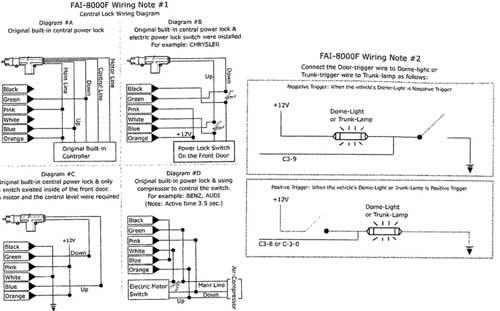
- Is there a function to light the dome (Courtesy) light? If so, how do I connect it?
- Are there any tricks / gottchas with the Ford Explorer door locks? Is it simply a reversing-polarity 2-wire system? My Explorer does not have factory keyless entry, but it does have factory power locks.
I have a wiring diagram for my vehicle: https://bulldogsecurity.com/New%20Wires/New%20Wires/Wires/explor92-94.htm
Thank you very much for your assistance.
Regards,
| | | |
|---|---|---|
| WIRE | COLORS | LOCATION |
| 12 VOLTS CONSTANT | YELLOW | IGNITION HARNESS |
| IGNITION 1 | RED / L GREEN | IGNITION HARNESS |
| ACCESSORY /HEATER BLOWER 1 | GRAY / YELLOW | IGNITION HARNESS |
| ACCESSORY /HEATER BLOWER 2 | BLACK/ GREEN | IGNITION HARNESS |
| STARTER | RED / L BLUE | IGNITION HARNESS |
| PARKING LIGHTS | BROWN(+) | AT LIGHT SWITCH |
| DOMELIGHT | BLACK/ L BLUE(+) | AT PIN SWITCH |
| PWR DOOR LOCK | PINK / YELLOW | DRV KICK PANEL |
| PWR DOOR UNLOCK | PINK/L GREEN | IF KEYLESS (TYPE B) W/O KEYLESS (TYPE C) |
| TACH SENSOR | TAN / YELLOW | AT COIL |
| BRAKE | GREEN(+) | SWITCH ON BRAKE PEDAL BRACKET |
| HORN | DARK BLUE (+) | IN STEERING COL HARNESS |
Replies:
Posted By: bmf1000d
Date Posted: January 23, 2004 at 12:57 AM
do you by any chance have the wiring layout of this alarm the only one i have is form a M7000 model and that is like from 2 years ago but ill post it
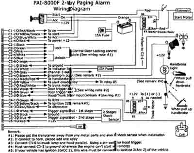
2. Wiring Chart

3. CN1
No 1 (White): (+12V) Accessory Output
This wire will read (using your digital multi-meter) OV with the key off, and 12V with the key in the accessory or 'ON' position.
The Accessory wire will usually drop out during cranking.
This wire supplies 12V to climate control and other accessories in the vehicle and is capable of supplying up to 30A.
Some vehicles do not have accessory wire - the ignition wire of such vehicles supply power to the accessories.
So don't connect this Wire for such vehicles.
No 2 (Yellow): (+12V)Start Motor Output
This wire will read (using your digital multi-meter) 12V when the key is in the crank position. This wire supplies power to the starter motor.
No 3 (Green): (+12V)Ignition Output
This wire will test (using your digital multi-meter) OV with the key off, and 12V with the key in the 'ON or RUN' position.
The ignition wire will not drop out during cranking of the vehicle.
This wire supplies 12V to the ignition coil and other electrical systems needed for the vehicle to run properly.
No 4 (Black): Chassis Ground
This will be the one of the most important connection.
Connect this wire to bare metal of the vehicle.
We do not recommend using the steering column for a grounding point.
Make sure you strip back the paint or use a factory grounding point.
Bad grounding on this wire will be the beginning of future troubles.
No 5 (Red): (+) 12V Constant
Solder this wire to the vehicle's 12V constant.
This wire must be supplied power all of the time and must be able to with stand high current draw.
No 6 (Violet): (-)Ignition Output
1. Installation of the solenoid valve for Benz Engines
Benz Vehicle has a vacuum hose underneath of the key ignition harness. The hose is vacuumed when engine starts with a key. To simulate this, a solenoid has to be installed to create vacuum for remote start.

2. Propane Gas Powered Vehicles
There is a gas valve switch for such vehicles. For remote start, this switch has to be turned on. There are two different types of switch.

4.CN2
No 1, No 2 (Violet): Positive Signal Light Output
Connect this wire to the (+) signal light wire on the vehicle. This wire will read (using your digital multi-meter) either open or ground before the signal light circuit is turned on and then it will read (+}12V after the signal light circuit is turned on.
No 3 (Yellow): Door Unlock Output
No 4 (Green): Door Lock Output
The following three door lock systems are the most common systems.


No 5 (White): (+)12V Siren Output
The Black wire at the siren is to be chassis grounded.
The siren volume can be reduced by cutting the volume wire attached to the siren.
No 6 (Black): (+)12V Trunk Output
If the vehicle is equipped with electrical trunk release, the trunk out is connected to trigger the trunk solenoid.

5. CN3
No 1 (Blue): Negative Starter-Kill output
Please use the pre-wired starter kill relay.


No 2 (Yellow/Black): Alternator sensing to monitor the engine running
This wire is to monitor engine running. Locate a small gauge wire from the alternator. When tested with your meter, it should show you about 2V when the key is on but the vehicle is not started.
When the vehicle is started using the key, the wire should read about 14V.
No 3 (RED / Black): Negative Trigger Door Open Sense
No 4 (Red): Positive Trigger Door Open Sense
Please make sure you have found a correct door sensing wire that monitors all doors.
No 5 (WHITE/ Black): Negative Glow Plug input
No 6 (White): Positive Glow Plug Input
If you donift connect one of these wires(negative or positive Glow sensing), the system will act as gasoline vehicles.
Only when one of these wires are connected, your system will know the diesel engine.
The differences between gasoline and diesel engine are pre-heating time and the running time(15 minutes for gasoline engine, 25 minutes for diesel engines) when remote starting.

No 7 (ORANGE / Black): Negative Parking Light Input
No 8 (Orange): Positive Parking Light Input

No 9 (Black): (-)Trunk Trigger Input
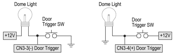
Connect this wire to the trunk lamp wire as shown below.

6.CN4
No 1 (Black): (-)
No 2 (BLACK/ White): (+)
7. CN5
| No 1 (Black): (-) No 2 (Blue): Sense No 3 (Red): (+) | Shock sensor |
8.CN6
| No 1 (Black): (-) No 2 (White): Sense No 3 (Red): (+) No 4 (Yellow): LED | Remote Pager sensor |

9. CN7
| No 1 (Yellow): RX No 2 (White): TX No 3 (Red): (+) No 4 (Net wire): (-) | Antenna Assy |
The antenna have been calibrated for horizontal installation at the top corner of the windshield.
Different installation may affect the transmitting distance quite seriously.

10. Transmitter Learning Routine

- Most vehicles
Step #1:
- Cycle the ignition key from the off position to the on position and back 3 times WITHIN 3 SECONDS thus giving the Green wire (harness #1) 12V 3 times.When this procedure is done the signal lights will flash one time to confirm that you are in the valet/programming mode.
Step #2:
- Once in the valet/programming mode and within 6 seconds, press Button "I" for à 1/2 second. The parking lights will flash once (and the relay inside the Controller will click once) to confirm that step #2 was completed.
Step #3
- Press button I on the new remote to teach it to the unit within 3 seconds of Step #2. The unit will accept up to 3 remotes. Each time when the unit has learned a remote, the parking lights will flash once (and the relay inside the Controller will click once) to confirm the programming of the remotes.
- If you learn only 1 remote, Press button I of one remote for three times so that any of the previous learning is deleted.
If you learn 2 remotes, press button I of the first remote two times and press button I of the second remote one time.
The parking lights will flash twice (and the relay inside will click twice) to confirm the completion of the programming.
- Benz types of vehicles that have vacuum hose underneath the ignition key box.
- Follow the same steps of the above 1, except that you use button III instead of button I.
The vehicle has a programming of automatic self-unlock when you turn off the engine with a key.
So, in this case you have to choose this Bentz type option programmed locks cloors upon remote-running end.
The controller generates a negative relay output for the relay that controls the vacuum hose.
- Follow the same steps of the above 1, except that you use button III instead of button I.
- Propane Gas Powered Vehicles
- Follow the same steps of the above 1, except that you use button IV instead of button I.
11. Programming Options with transmitter
- Changing Delay Time and Door Lock Pulse Timing
The factory setting: The delay time between ignition output and the starter output for remote start is 4 seconds.
The duration of the door lock pulse is 0,8 seconds.
You can change that through this procedure.
Step 1: Key=0n, Engine=0ff, then Press button [I+II] for 2 seconds. You will be confirmed by 1 chirp. If you hear 3 chirps, do it again.
Step 2: Change the setting by pressing one of the 4 buttons as follows. You will be confirmed by 2 chirps. If you hear 3 chirps, please repeat starting Step 1.
Option Programming Delay Timing Door Pulse Button I 4 sec 0,8 sec Button II 10 sec 0,8 sec Button III 4 sec 4 sec Button IV 10 sec 4 sec - Option programming for Anti-Jacking, Anti-Grinding, Signal Light Flashing
Anti-Jacking: The #1 wire of CN3 can be programmed to send a signal to a relay to disconnect the ignition wire of the vehicle upon anytime the vehicle is armed so that the vehicle cannot start or run by a remote or a key. And the running of vehicle can be shut off by remote's panic command.
Starter-Kill and Anti-Grinding: The #1 wire of CN3 can be programmed to send a signal to a relay to disconnects the starter wire of the vehicle upon arming and upon remote-start to prevents you from re-cranking the starter on a remote - started vehicle.
Signal Light Flashing: This mode makes the signal lights flash if any of the doors remains open while the vehicle is not armed.
The factory setting is Anti-Jacking mode and Signal Light Flashing.
You can change this setting as follows:
Step 1: Key=On, Engine=Off; then press button [I+V] at the same time for 2 seconds. Confirmation: 1 chirp; if you hear 3 chirps, repeat step 1.
Step 2: Press one of the 4 buttons. You will be confirmed by 2 chirps. If you hear 3 chirps, Please go back to the step 1.
| Option Programming | Mode | Light Flashing |
| Button #I | Anti-Jacking | Light Flashing |
| Button #II | Anti-Jacking | X |
| Button #III | Anti-Grinding | Light Flashing |
| Button #IV | Anti-Grinding | X |
-------------
"Big" Mike
Double Take
Fremont, Ne
remember to check all your wires with a dmm not a test light!!
i take no responsibilty whatsoever for the vailidty of the info nor consequences thereof
Posted By: areese
Date Posted: January 23, 2004 at 8:18 AM
Please forgive the quality of the picture - in order to get it under 30k for upload, the quality took a hit. If you've an email address I could send a better picture to, I'd be happy to do that.
Thanks for your help!
...andy
-------------------------------