This should be easy for you electronic people. I need some solid advice and description so I can finish my install.
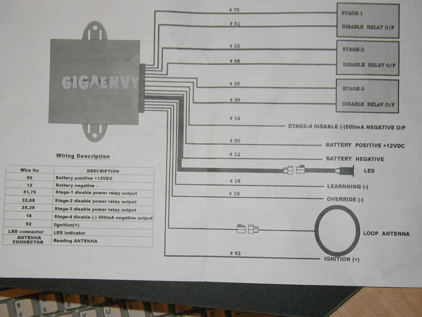
I bought an IMB-2000 or TR-3 (some asian product most likely). It has 3 built-in Disable Output Relay N.O.'s. I want to use the first set (Stage-1) with wires #75 and #51 (see picture). To enable the relay you need to swipe a keyfob (speedpass type) near the antenna to start the car. Without swiping the car won't start because the internal relay has not closed. My problem is connecting these two wires (#75 and #51)and need some direction.
I identified two fuses and found the wiring behind the fuse panel for the ECU and Fuel Pump. I think I will try the fuel pump for the Stage-1 setup. There are two wires that go into the fuse jack for the fuel pump behind the panel.
Given this example....how do I connect the Stage-1 (per diagram) to the wiring of the fuel pump fuse bank behind the panel? I know I need to cut but do I cut only one and create a bridge using #75 and #51 or something else?
Please look at this diagram and help me out. I thank you all alot!
Regards,
GigaEnvy
What kind of car and year of car is this going into ? According to the diagram this looks to be a disable module, not an immobilizer bypass module. You will still need to purcahse an immobilizer bypass module and using just this IMB-2000 will not help you do that. From the picture you have the LOOP Antenna that goes where ? Over the key cylinder or over the actual transponder key ? Can you scan in the instructions for this module ?
-------------
Jeff
Velocity Custom Home Theater
Mobile Audio/Video Specialist
Morden, Manitoba CANADA
Do you have remote start and your trying to bypass the vats system or what? If its a vats type system put a digital meter on the chip on the key (non polarized) , whatever the ohms read thats what resistor replaces it .The right resistor and a relay should do everything that box will. On gm I believe the wires are in an orange sleeve and can be found at the lower steering colume.
Actually, it looks like he is trying to install a transponder (or passive) immobilizer. It looks like the 75 and 51 wires are simply your COM and NO contacts on the internal relay. You should be able to cut your fuel pump wire and connect 75 to one side and 51 to the other. It shouldn't matter which side is which since it is just breaking (and reconnecting) the circuit.
Mike
-------------
Mike
Sales/Tech Support - KICKYRIDEoCOM mobile electronics
MECP 1st class-Security Specialist
I second that !
its a transponder Immobiliser alright. it is capable of cutting three circuits.
as Kicky says its as easy as connecting one end up to the feed and the other to the supply wire.
-------------
"you wont like me, when i get angry" .