installing a viper 791 on this vehicle, i am aware that you can use the remote to slide the doors on the vehicle can anyone please help me out on how to have the doors functioning the same with the viper alarm
if anyone have any info for ex: like wire diagrams on this vehicle and also any diagrams on how to wire up the doors to slide with the viper alarm i will appreciate that thanks again for your time fellas
-------------
Kenny
Not sure about the doors but here is the rest.
Remote Starter Wiring Colors and Notes |
Function | | Vehicle Color | Location |
Start: | | BLACK/ White (+) | Ignition switch harness |
Ignition #1: | | BLACK / YELLOW (+) | Ignition switch harness* |
Ignition #2: | | BLACK/ Red(+) | Ignition switch harness |
Ignition #3: | | N/A | Ignition switch harness |
Accessory: | | WHITE/ Red(+) | Ignition switch harness |
Brake Light: | | WHITE/ Black (+) | Brake pedal switch |
Tach Signal: | | Not Yellow/Black(AC) | Any Fuel injector |
Parking Lights: | | RED / Black (+) | 17 pin harness at the bottom of the fuse box |
Headlights: | | N/A | |
Diesel Glow Plug: | | N/A | |
Clutch Bypass Wire: | | N/A | |
Notes: | | *This vehicle is equipped with a Transponder Anti-Theft system. Use Universal Alarm Bypass Module part # 2x402 where X can be any number. You may also use Vehicle Specifit Bypass Module part # 23551. **The tach test connector is a 2 pin plug above the brake master cylinder. |
Alarm and Keyless Entry Wiring Colors and Notes |
Function | | Vehicle Color | Location |
Constant +12 Volts: | | White (+) | Ignition switch harness |
OEM Alarm Disarm: | | BLACK/ red or White | Drivers door module inside the door |
Dome Lights/Superv: | | BLACK/ Red (-) | Domelight on/off switch |
OEM Horn: | | Lt.GREEN/ YELLOW (-) | Steering column harness |
Power Lock: | | Not available | |
Power Unlock: | | Not available | |
Trunk Release: | | N/A | |
Alarm Input Wire: | | BLACK/ Red (-) | Domelight on/off switch |
Notes: | | **See Note #201 Negative Trigger Door Locks |
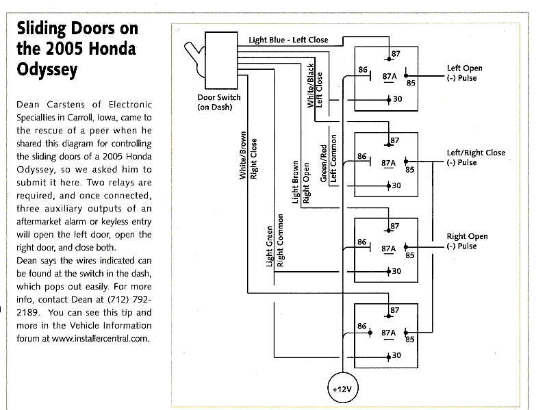
If youo have access to Mobile Electronics magazine the March 05 issue has the diagram on page 85.
It requires 4 relays the wires are easily located at the switch on the dash.
If i get a chance i will try to scan it and post it for you.
Here is the diagram. I hope, never posted a pic before.