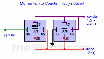
I have a 99 ford excort zx2 and i just bought a keyless entry system. I was wondering if there was any way to make the trunk release button turn my neon lights on and off instead of opening the trunk.
-------------
FreakyStyley990
yes you can! you would need a latching relay and use the output of your keyless seytem, trunk pop output in your case, to "latch" the relay off and on. If you have any problems just post a question to me and I should have a schematic available for you!
'
-------------
Ruben
Innovative Sounds
Phila., Pa.

The constant 12v+ output is what you hook up to your neon lights.
You will not be able to turn them off with this setup, you must add another relay to break the continuity. for example you could use your lock wire to activate a relay that would break the continuity of the ground wire on pin 86 of the relay on the right. That is 3 relays though. So trunk button would turn them on, and lock would turn them off.
I am pretty sure 3 relays is the only way to be able to turn them on and off given that you have a negative input and need a positive output.
I'll keep thinking though
-------------
J Rilla
Owner/Installer
You can purchase a latching relay from either Micro Alarms or TRC.
I have used both the mechanical relay setup they sell and the electronic one with no preference to either one other than space.
-------------
(owner/installer)
Chase's Accessories
Ridgecrest, CA
in business since 92
JRILLA: Can you show me how you would wire the relay to break the continuity and turn them off?
CHASESACC: I went to Micro Alarms website and there was no way to order from them. Can you give me a website that I can order these latching relays from?
-------------
FreakyStyley990
I dont have a diagram but it is really simple:
You see the ground wire on pin 86 of the relay on the right: this is the wire you will break the continuity with. so on the 3rd relay pin 87a will actually go directly to pin 86 on the relay on the right, and pin 30 will go to a good chassis ground. 87 gets nothing and 85 and 86 get your negative lock wire and 12v+.
-------------
J Rilla
Owner/Installer
jrilla, thanks for your help. sometimes all this relay stuff gets a bit confusing for me.
-------------
FreakyStyley990
Hey no problem, a long time ago I was asking a lot of question to a friend and he stopped and he gave a 10 second review of relays that stopped my questions ever since. so here it goes. 85 and 86 need one pos and one neg to energize the coil inside the relay that takes pin 30 from its resting place at 87a and connects it to pin 87. So if you have a negative trigger on 85 then you need 12v+ on 86, and if you have a positive trigger on 85 then you need to ground 86. and if you want to trigger something that requires a positive pulse, you hook up pin 87 to 12v+ and pin 30 to the wire that requires the positive pulse, and if it requires a negative pulse then pin 87 gets grounded and pin 30 goes to that wire that requires ground to be activated. In your particular case you used pin 87a since you wanted continuity in the ground wire on the relay on the right, up until you decided to shut off the lights, so you used you your lock wire to trigger the relay to diconnect that ground wire betwwen pin 30 and the relay on the right, by sending it to pin 87 where there was nothing, which in turn de-energized the latched relay.
I really hope i didnt confuse things I tried to keep it simple at the beginning but then I couldn't help myself. Nevertheless, this is all very basic and there are endless ways to wire endless possible functions, but this should help you be able to think through your next relay problem.
if I have confused you and you would like to have it clarified i will be more than willing to do so, or you can just click on the "relays" link in the column on the left of this page and read more about them. There are more diagrams there too.
If you want more diagrams, go to www.relayhelp.com
-------------
J Rilla
Owner/Installer
Contact Micro at (800) 736-2999 part #PBS89R
I don't have TRC's # (the Right Connection)
-------------
(owner/installer)
Chase's Accessories
Ridgecrest, CA
in business since 92
