alarm to a car horn
Printed From: the12volt.com
Forum Name: Car Security and Convenience
Forum Discription: Car Alarms, Keyless Entries, Remote Starters, Immobilizer Bypasses, Sensors, Door Locks, Window Modules, Heated Mirrors, Heated Seats, etc.
URL: https://www.the12volt.com/installbay/forum_posts.asp?tid=65059
Printed Date: May 16, 2026 at 8:38 AM
Topic: alarm to a car horn
Posted By: zizmo
Subject: alarm to a car horn
Date Posted: October 26, 2005 at 3:04 PM
Here is my problem. As you can see on the diagram I made, I connected the alarm to a car horn, the problem is that when you enable or disable the door locks the input are just three pulses. I can hear the three pulses activating the relay three times but the problem is when it reaches the flasher. As you can see the three pulses become just one very low pulse which I can barely hear. I dont mind it being just one pulse, but I would like to hear it louder so I can know if I really locked my car. On the other hand when the alarm is active the input is one long pulse until it is deactivated. The output works perfect they are long and loud pulses as they should be. What can I do about that small pulse? Any ideas? 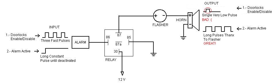
Replies:
Posted By: Velocity Motors
Date Posted: October 26, 2005 at 3:19 PM
From the diagram it looks like you have (+) door lock output to the relay , is this correct ? If not, what you can do is wire in a relay to go directly to the horn from the door locks output of the alarm system. This will bypass the flasher and you will be able to use the output of the door trigger's to go directly to the horn.
-------------
Jeff
Velocity Custom Home Theater
Mobile Audio/Video Specialist
Morden, Manitoba CANADA
Posted By: Velocity Motors
Date Posted: October 26, 2005 at 3:19 PM
BTW, you will need to use diodes to isolate the trigger's.
-------------
Jeff
Velocity Custom Home Theater
Mobile Audio/Video Specialist
Morden, Manitoba CANADA
Posted By: zizmo
Date Posted: October 26, 2005 at 4:43 PM
The problem is that with this alarm, when you start the car the locks close automatically and when you turn off the car they open automatically. So my guess is that if I wire a relay from the door locks to the horn it will beep every time I start or turn off the car. Any ideas?
Here is the diagram of the alarm, due to the size restriction I hope its visible. 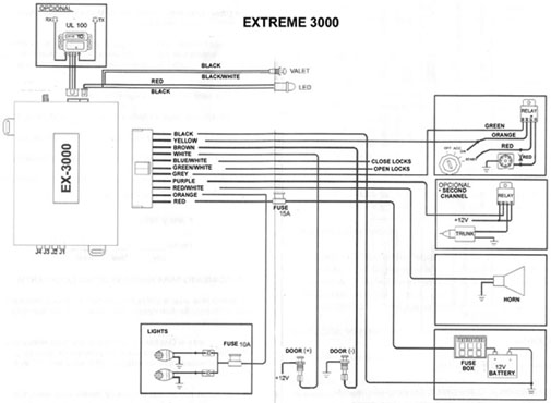
Posted By: dualsport
Date Posted: October 26, 2005 at 11:33 PM
You can add a pulse stretcher circuit using monostable, or a mosfet and a few discrete components, so the relay will stay on for a half second or so when the alarm pulses.
Either that or you could just add an extra electronic siren that'll respond quick enough for you to hear the short chirps.
Posted By: zizmo
Date Posted: October 30, 2005 at 9:16 AM
Sorry for my ignorance but how can I make a pulse stretcher circuit, do you have any schematic?
Thanx for the idea
Posted By: dualsport
Date Posted: October 30, 2005 at 12:03 PM
I don't have an easy way to draw up schematics as nicely as you have there, but maybe I could describe it-
Using something like a 2N7000 MOSFET or equivalent (I bought a bag of 100 from mouser.com for 8 cents each)
2N7000
This is a very high input impedance transistor, so it draws no current from the trigger signal.
Connect your alarm siren output signal to the gate of the transistor through a diode, forward biased, so it passes current when the signal goes high.
Connect a resistor and capacitor in parallel, and put one side of the leads to ground, and the other side to the transistor.
What this does is allow the cap to charge up quickly through the diode when your signal comes on, and then when it shuts off again, discharges slowly through the resistor. If you pick a large resistor, the transistor will stay on for a longer time. The source of the transistor is connected to the coil of a relay, and the drain to ground (relay set up for ground trigger actuation, with constant 12V on the other side of the coil).
I'd add another diode across the source and drain of the transistor for added protection from the relay coil kickback when it switches off, especially if you happen to be using a large relay, since they can produce a large voltage spike when turning off.
You can experiment with the values of resistor and capacitor to give you the desired time needed for the arming pulse, since your flasher may add a delay before sending the power to the horn. Rough timing should be about resistor x capacitor values, so you could start with a 10uF cap and 100k resistor for an output of about a second, and change them as necessary.
A larger cap will increase the pulse duration, as well as a larger resistor.
Try to avoid static when handling the transistor before everything is hooked up, since it's sensitive to ESD, electrostatic discharge. For 8 cents a piece though, <shrug>.. 
Posted By: dualsport
Date Posted: October 30, 2005 at 12:10 PM
Oops, wrote it backwards in the description there; the source (S) should go to ground, and the drain (D) of the transistor goes to the relay coil, not the way I described up there.
Here's the datasheet for the transistor, which shows which leg is which on the transistor.
Might be good to use a potentiometer as a resistor, so you can tweak the thing as needed, in case you want a longer or shorter pulse.
Posted By: zizmo
Date Posted: October 30, 2005 at 2:00 PM
Well thank you very much! I will try that!
Posted By: zizmo
Date Posted: October 30, 2005 at 2:59 PM
Did you mean something like this? Is the diode of the transitor ok or should it be backwards? The transistor is always conducting, when it receives the pulse it stops conducting and that activates the relay? 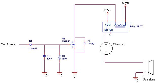
Posted By: dualsport
Date Posted: October 30, 2005 at 4:09 PM
Yep, that's the right way- what do you use to draw the schematic? Looks good.
The transistor turns on whenever you get a positive voltage on the gate, so it basically switches the relay coil to ground, turning on the relay. When the gate to source voltage is greater than about 2V or so, the transistor turns on, when it's less, it turns off.
When your alarm goes high, the diode conducts, charges up the C1 capacitor, which turns on the transistor.
When your alarm pulse goes back low, the D1 diode prevents the cap from discharging back through the alarm trigger and turning off the transistor again; instead, the cap has to discharge back to ground through R1.
If you have a larger value for R1, it does it slowler, so the transistor stays on for a longer time; once it does eventually discharge, the transistor turns off again, and the relay opens up. Also, if you have a small cap, you can see that the time required to discharge would be shorter, so the pulse is correspondingly shorter.
Posted By: dualsport
Date Posted: October 30, 2005 at 4:16 PM
Oh, I notice you have the relay hooked up to the normally closed side of the contact; it should actually be connected on the normally open side.
That way, the siren only gets powered up when the transistor is turned on, energizing the coil.
Posted By: zizmo
Date Posted: October 30, 2005 at 4:19 PM
Yeah I also notice that when it was already too late lol I used Orcad PSpice to draw the schematic, its a really nice program because you can also simulate the circuit. Thanx
Posted By: dualsport
Date Posted: October 30, 2005 at 4:27 PM
Handy program, I'll have to see about loading my pc up with it too. I started to try using autosketch to draw it up, but it was too ridiculous trying to draw the components out when it should have needeed just a single mouseclick- 
If you don't want to buy a hundred of these things to play with like I did, you could SASE me and I'll drop a couple in for you to try out; I have plenty-
Posted By: zizmo
Date Posted: October 31, 2005 at 1:18 PM
Well thanx a lot but I live in Mexico  so its gonna be a little bit difficult lol so its gonna be a little bit difficult lol If I dont find 2N7000 what other could I use?
Posted By: dualsport
Date Posted: October 31, 2005 at 5:40 PM
It's also equivalent to a BS170, but that probably isn't any easier to find. Hell, these things may be made there, in Mexico for all we know-
You can use pretty much any MOSFET transistor, since all it's doing is switching on and off; using it to drive a relay takes very little power, so anything you can find would probably work fine.
The 2N7000 and BS170's just happen to be small and cheap, since there's no point in using the expensive ones that can handle hundreds of amps and volts, when 8 cents will do the job-
|