Delayed relay output?
Printed From: the12volt.com
Forum Name: Car Security and Convenience
Forum Discription: Car Alarms, Keyless Entries, Remote Starters, Immobilizer Bypasses, Sensors, Door Locks, Window Modules, Heated Mirrors, Heated Seats, etc.
URL: https://www.the12volt.com/installbay/forum_posts.asp?tid=65562
Printed Date: March 29, 2026 at 9:39 AM
Topic: Delayed relay output?
Posted By: icarus_icarus
Subject: Delayed relay output?
Date Posted: November 03, 2005 at 7:07 PM
I just wanted to say I've been browsing around the forum for a while reading different items, learning a fair bit from everyone and have liked what I've seen! Now I have decided to join and ask for some help! I was looking at the diagram below from this site and the one on "Momentary to Constant Output" , is there any way anyone knows that I could use something similar to these (combine them somehow), but using a (7/10sec.) accessory pulse from a remote starter to turn on a 10 minute delay to power up a defrost grid? I was going to hook a relay across the factory switch, but the connections to turn it on properly are internal and I don't feel like breaking open the switch. If this is possible, what size capacitor would I need to make it stay on for approx 10-12 minutes? 
Thanks for any help you can provide. I will keep reading through the forums to see what else I can find as well! Jon
Replies:
Posted By: fingaz22
Date Posted: November 03, 2005 at 7:54 PM
you have the wrong diagram you can use just one relay and get your 12v turn on for the relay from the ass. wire on rs. put a diode inbetween the factory harness and where you tap the wire coming out of the rs. so it will shut off when you press the brake and the diode will prevent juice getting back through the wire to the relay from the ign. ass.
-------------
JUST ONE MORE AMP!!!
hu,alpine cva 1005/dva 5205
sound processor,symmetry(first one).
sub amp,power 1000 the terminator.(1992).
subs,spl comp dual 1 ohms.
punch 150hd on a 10" ev.
alotofhighs
Posted By: icarus_icarus
Date Posted: November 03, 2005 at 11:50 PM
Yah, I was thinking of doing that at first as well, but want to be able to control it so it's used only when needed... I've been watching the info in the other guys thread that is in a similar dilemma as me that you posted in too fingaz. I was hoping there would be some way to get it so its timed longer (the diagram I posted says it will stay on for only 1/2 sec., I need about 10-12 minutes) plus I wanted it triggered by the momentary output on my RS like I mentioned... Unfortunately my output in not programmable, just a 7/10sec. pulse it supplies...
Posted By: fingaz22
Date Posted: November 04, 2005 at 6:59 AM
well i had that in mind but it will not shut off like a factory one will. if you were to use the momentary to constant. and like in the other tread if you can tap into the defrost switch and it is the same style switch that will work. what kind of car and what year i will look up your defrost curcuit and be able to help alot better. lol
-------------
JUST ONE MORE AMP!!!
hu,alpine cva 1005/dva 5205
sound processor,symmetry(first one).
sub amp,power 1000 the terminator.(1992).
subs,spl comp dual 1 ohms.
punch 150hd on a 10" ev.
alotofhighs
Posted By: dualsport
Date Posted: November 04, 2005 at 9:14 AM
Take a look at this Post
and see if you can try that to provide your timed output. The circuit he drew out is for a short pulse output, but you should be able to use it too-
You just need to use a larger cap and resistor to stretch out the 'on' time.
Posted By: icarus_icarus
Date Posted: November 04, 2005 at 4:07 PM
I can post up a pic of the defrost circuit for you if ya want, but the one side of the timed circuit is internal. I even had the switch out and tried taking it about, but don't want to screw it up... I'll dig it out and show it to ya when I plug in my scanner :) Thanks
Posted By: kgerry
Date Posted: November 04, 2005 at 4:21 PM
most newer RS units have a dedicated defroster output..... you may want to check the unit you are putting and save yourself a bunch of time....
-------------
Kevin Gerry
Certified Electronics Technician
MECP First Class Installer
Owner/Installer
Classic Car Audio
since 1979
Posted By: icarus_icarus
Date Posted: November 04, 2005 at 7:33 PM
The unit I have is just a cheaper AutoStart unit from Canadian tire... It doesn't have a seperate wire for the defrost nor is it very programable with its options :(
Posted By: dualsport
Date Posted: November 04, 2005 at 8:16 PM
If you don't want to get into the factory switch, then wire it up to the defroster grid inputs using the add on timed relay. I assume that's where you're planning to connect to.
Then you can just pulse it once with your alarm and have it come on for a short time before turning off again.
Posted By: icarus_icarus
Date Posted: November 04, 2005 at 8:31 PM
That's what I'm trying to figure out... How to supply power to the actual defrost wire with a relay setup that is actuated with a pulsed output from the RS and is timed for 10 minutes or so (bypassing the factory switch)...
Posted By: dualsport
Date Posted: November 04, 2005 at 8:36 PM
Take a look at this Post again
and see if you can use that to provide your timed output. The circuit he drew out is for a short pulse output, but you should be able to use it too-
You just need to use a larger cap and resistor to stretch out the 'on' time to 10 minutes.
Posted By: icarus_icarus
Date Posted: November 04, 2005 at 9:00 PM
The part that says 'Switch and Time Delay' in the diagram is internal on the switch. I don't know enough to figure out exactly what to do with your description in the other guys post dualsport, sorry... I have no idea what size cap or resistor to use etc...
Posted By: dualsport
Date Posted: November 04, 2005 at 9:43 PM
To get about 10 minutes, you can try a cap value of 100uF and a resistor of 5.6Mohms, then if you wire it up as shown in the other post, you can connect the relay across the wires on the right side of the defrost switch relay assembly. To be safe, you should probably cut the BR/LB wire at the bottom and use the NC to COM (with the COM going to the defrost grid side, and the NC to the OEM defrost relay side) contacts of your added relay to reconnect it when you're not controlling it remotely. Then when you power up your added relay, the grid will get power from the NO contact, which is connected to the top BK/Y wire.
If someone can confirm that it won't bother the OEM defrost relay to have 12V applied directly to the grid, then you don't need to bother with the NC connection scheme. My guess is that it'd probably be okay, but better to be safe and not risk damaging the OEM relay timer circuit.
Posted By: icarus_icarus
Date Posted: November 04, 2005 at 10:51 PM
Cool, thanks, I think that makes sense now! :) Will 1/4 watt 5% resistors, and aluminum electrolytic caps work for this? (typical resistors and caps found at Radio Shack etc) I don't know of any places around here other than Radio Shack (theSource up here now) that sell stuff like this, I'll have to look around to see where I can get the transistor from :( So theres no way I can do this with just relays/caps/diodes similar to the original picture?
Posted By: icarus_icarus
Date Posted: November 04, 2005 at 11:27 PM
dualsport, what about something a 'lil simpler like this: 
My understanding of this circuit was a single pulse will energize the relay according to what size cap and resistor you use... If I used the cap and resistor values you mentioned, would a single pulse from the RS keep this energized for time I want?
Posted By: icarus_icarus
Date Posted: November 04, 2005 at 11:32 PM
ps: Maybe to clarify my inquiry (or confuse me more about the above diagram!): I know I wouldn't have a constantly pulsing input to the 86 terminal of the relay, but all that does is reset (recharge) the cap so its on constantly, hence it would stay on after the last pulse (or just the one pulse as in my case) for the time determined by the cap and resistor?!... I hope I'm not reading into this more than I need to as I know I am bad for this at times!
Posted By: icarus_icarus
Date Posted: November 04, 2005 at 11:34 PM
oh, and terminal 30 of the relay would goto the BR/LB wire of my car diagram...!?
Posted By: dualsport
Date Posted: November 05, 2005 at 8:18 AM
That circuit wouldn't work for the timing period you're looking for; you need to put the transistor in place to drive the relay. The relay coil draws a relatively large current, and what would happen is that it would discharge your cap almost immediately once the trigger signal turned back off. You'd need an enormous cap, which your drive signal probably wouldn't even be able to charge up in time.
With the transistor, it's basically voltage driven, and draws essentially no current during the 'on' period. Then, once your trigger signal turns off, the cap can only discharge through the resistor, since the only other paths would be the reverse biased diode and the transistor, which like open circuits.
The circuit just extends the on period from when you turn off your trigger signal; if you put in a constant on (+) signal, the relay would stay on for as long as it's high.
Yes, term 30 should be the COM contact of your relay, and should go to the BR/LB defroster grid wire side.
Just occurred to me you might be using a (-) signal from the alarm; not a (+) pulsed signal; if that's the case, it would have to be inverted first to get a signal that goes to +V when you push the remote control.
Your diagram shows the power input to the defrost relay to be constant 12V; connect the (+) of your relay coil to source that only goes on when the car is remote started, so it can't come on at any other time.
You can check online at Mouser.com for the parts, they don't have a minimum order, so you'd just need to spring for the shipping charges. May as well get a bunch of stuff with assorted values if you do order.
Posted By: icarus_icarus
Date Posted: November 05, 2005 at 1:49 PM
I didn't realize this about the current across the relay coil, I'm learning though! I checked out Mouser, but they list hundreds of different things for resistors/caps/etc... I'lll have to look around when I have some more time to sit down and check out thier site... I do have a (-) signal from the RS, so figured I had to invert it as well. Is there any kind of formula or way of figuring out what different size caps and resistors will do to the timing of the circuit so when I do order stuff I can tweak it a bit if need be? Thanks for the great info you have been posting dualsport, it's nice to see someone willing to help so much! Jon
Posted By: kgerry
Date Posted: November 05, 2005 at 4:27 PM
or you could just use the DEI 611T which will do exactly what you want.... it's a timed latching relay module
-------------
Kevin Gerry
Certified Electronics Technician
MECP First Class Installer
Owner/Installer
Classic Car Audio
since 1979
Posted By: icarus_icarus
Date Posted: November 05, 2005 at 4:59 PM
kgerry wrote:
or you could just use the DEI 611T which will do exactly what you want.... it's a timed latching relay module
I thought the 611T only would time up to 100 sec. and was rated for 5A?
Posted By: dualsport
Date Posted: November 05, 2005 at 5:55 PM
An easy and rough way to estimate the time delay is to take the capacitance and multiply it by the resistance, to give you the seconds. That should get you in the ballpark, which you can tweak up or down as necessary.
100uF would be 10E-6, or 0.000010 farads
5.6Mohm is 5.6E6, or 5,600,000 ohms
Find some combination that will give you the 600 seconds for your 10 minute delay.
I'd just get the cheapest resistor you can find there, don't worry about power rating at all, since it's really not going to be anywhere near the smallest one you could ever find. It'd take over a thousand volts for it to reach just a 1/4 watt.
Same thing with the caps, a cheap electrolytic would do the job, no need to get the fancy stuff.
Posted By: icarus_icarus
Date Posted: November 05, 2005 at 8:06 PM
So, like this? 
Posted By: dualsport
Date Posted: November 05, 2005 at 10:00 PM
Yep, that should work- use a switched line for the +12V to the relay that only goes high when you're in remote start mode, like ignition, and you should be in business.
You can use a small relay for that inverter, since you don't need to use a high current one (unless you've already got a bunch stocked up).
And what did you use to draw this up? Looks like everyone can draw out neat schematics except me- 
Posted By: icarus_icarus
Date Posted: November 05, 2005 at 10:31 PM
I used Paint Shop Pro  I've got a bunch of Bosch relays here already so figured I'd just use two of them, actually the only thing I need is the transistor (well, I'll have to put a few resistors in series to get 5.6M thou!) I figured I could hook the ground to the 'ground out while running' on the RS so it would only works while under remote start...
Posted By: icarus_icarus
Date Posted: November 05, 2005 at 11:34 PM
Daymm, that Mouser.com site has alot of stuff! The more I look at it the less I feel I ever knew about this things! lol...
Posted By: dualsport
Date Posted: November 06, 2005 at 12:43 AM
Yep, lots to play with; all ya need is the time! 
Posted By: KPierson
Date Posted: November 06, 2005 at 12:03 PM
Instead of building a timer why don't you just use the timer of the remote start? Assuming the remote start only stays activated for 12 mintues (estimate) that would be a perfect timer. You could cut down your parts list tremendiously. Use the (-) channel to activate the relay on the right. This relay will get its positive from the accessory out of the RS (so it will only latch when the car is remote started). The relay on the right will provide a latch to the relay on the left. Since you are using the accessory output you will need to diode isolate the accessory circuit of the vehicle, this is the only 'snag'. If you have access to the 3A diodes wire four of them in parallel. So, you remote start the car. Both relays have 12VDC on one side of the coil. You hit the AUX button and both relays pull in. They will stay energized for as long as the car is remote started. When you end the remote start session you can manually turn the defroster on. 
------------- Kevin Pierson
Posted By: fingaz22
Date Posted: November 06, 2005 at 5:40 PM
check this out it mite helphttps://www.the12volt.com/installbay/forum_posts.asp?tid=65372&PN=0&tpn=1 lol.
-------------
JUST ONE MORE AMP!!!
hu,alpine cva 1005/dva 5205
sound processor,symmetry(first one).
sub amp,power 1000 the terminator.(1992).
subs,spl comp dual 1 ohms.
punch 150hd on a 10" ev.
alotofhighs
Posted By: dualsport
Date Posted: November 06, 2005 at 6:59 PM
Yeah, good idea using the timed remote start period- sounds like the best way to go for this application, the pencil vs. space pen -
If you add a diode between 87 and 85 of the right relay, (stripe towards the 87) it'll latch with a momentary (-) pulse from the remote start, if you don't want to configure it in latched output mode. That way you don't have to keep track of whether the control output is latched on or off.
Posted By: icarus_icarus
Date Posted: November 06, 2005 at 8:40 PM
The second relay has 3 terminals going to ground (87,30,85)? I already have two circuits running off the acc wire, so could I wire it with a constant 12V and have the ground goto the 'ground out while running' wire on the RS? Would this do what I want?
Posted By: dualsport
Date Posted: November 06, 2005 at 10:06 PM
Well, if you use a constant source like that, it's not going to be timed, and will stay on all the time once you turn it on (!).
It'd be better to use the 12V source that's only active during the remote start (the wire from the remote start that feeds the accessory) just as he drew in the original diagram, because it has to be able to turn off to shut the relays off again.
You don't really need to use the ground out while running for term 30 on the second relay, though that would work fine also. If it's any easier, just connect to any constant ground you can get to. Term 85 on the second relay is just the trigger input to turn on the relay, not a constant ground.
The added diode lets you remove the trigger input and keep that second relay latched, because when the relay closes, term 87 gets connected to ground, and then holds the trigger term 85 at ground (through the diode) as long as term 86 stays at 12V.
That's why you need to be able to remove the 12V to the second relay when the remote start period is over, in order to shut the relay back down.
If your remote start period is longer than you want to leave the defroster on for, you'd have to shut the remote start off manually to turn off the defroster, then restart. If it's only few minutes more, it should be no problem to run the defroster longer.
Posted By: dualsport
Date Posted: November 06, 2005 at 10:30 PM
As KPierson said, the part you have to be careful with is getting the isolation diode with enough current capacity to supply the full current draw of all your accessories. Not sure what the current rating on the accessory output from the alarm is, but that should probably be the minimum value to shoot for when selecting the diodes. I
An alternative is to use that "ground out while RS" signal as the relay enable line; then you don't have to get the high current diodes-
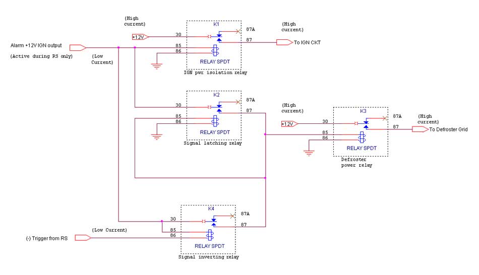
Don't have drawing capability, but here's the details:
3 components: two relays, one standard low pwr diode
Relay 1:
Term 30 to 12V Constant (high power for defroster pwr)
Term 86 to your "Ground while RS" signal
Term 87 to Defroster Grid
Term 85 to Relay 2 Term 30
Diode between Relay 1's term 87 and 85 (stripe towards 85)
Relay 2:
Term 87 to 12V Constant (low pwr)
Term 86 to 12V Constant (low pwr)
Term 85 to (-) trigger pulse from RS
That should do the trick-
Posted By: dualsport
Date Posted: November 07, 2005 at 1:08 PM
Got set up for schematic drawing now- 
Posted By: icarus_icarus
Date Posted: November 07, 2005 at 3:03 PM
So this will 'latch' on when I hit the aux button on the remote, and only while running under RS, for the time I have the module set for (15minutes) & I don't need to worry about the higher powered diodes/transistors etc! Sounds great to me! I'm impressed to see a forum where everyone is willing to help out so much, you don't see this alot, esp to the extent you guys have been helping me! I hope to return the favor when I can. Thank you. I'm going to finish this up this week if I get some time between work. I'll let ya'll know how it turns out :) Jon
Posted By: dualsport
Date Posted: November 07, 2005 at 3:53 PM
It's a little like doing crossword puzzles, just for fun-
At least now I can draw the schematics out, should be handy.
Hope it works out, let us know!
Posted By: icarus_icarus
Date Posted: November 07, 2005 at 4:08 PM
What program did you end up using for the drawings?
Posted By: dualsport
Date Posted: November 07, 2005 at 4:21 PM
I used Orcad Capture, makes it really easy; all the components are available to just drop onto the page without needing to draw them out, like I started to do with a sketch program. That was waay too tedious, so I gave that up real quick..
Posted By: icarus_icarus
Date Posted: November 07, 2005 at 5:00 PM
On relay K2, does it matter the source for the 12V @ term 86? (ie: can it and 87 be powered by the same 12V?)
Posted By: dualsport
Date Posted: November 07, 2005 at 5:16 PM
They're the same, so you can just connect them together. You can just use light gauge wire for those, because all they do is drive the relay coils; the high power one is the one feeding the defroster, so you should use wire of sufficient gauge to handle the current there.
Posted By: icarus_icarus
Date Posted: November 07, 2005 at 5:45 PM
I have many spools of 14ga automotive wire (or is it 16ga?!) and some 10ga I will use for the defrost line (the factory line is 12-10ga for the defrost) ...soldering the diode to this should be fun ;) I used to have a program similar to Orcad where you can design and 'test' circuits, I'll have to dig it out and see what one it is if I can even find it now! I did find my box full of resistors, caps, and other goodies though :)
Posted By: icarus_icarus
Date Posted: November 09, 2005 at 2:16 AM
I hope you guys don't shoot me for this, but guess what I got apart??? The blue arrow is what the toggle switch presses against to turn the defrost on/off... The red arrow is a middle connection on the metal bar running around the coil (there is three connections to the board on the bar ... ... The green arrows are the real fine wires going to the coil itself... 
Now should I ask is there a way to use a relay to activate it using the factory timer etc? I can scan the backside or do an overlay of what wires go where from the other wiring diagram if need be... Thanks, Jon ps: the starter is in totally now, just need to hook up the power wires and this defrost idea if it happens :) I'd still be pondering all this if it wasn't for you guys though!
Posted By: icarus_icarus
Date Posted: November 09, 2005 at 2:18 AM
Well, it will happen, either the way you have already done for me or if I can do something with this now 
Posted By: danijels
Date Posted: November 09, 2005 at 4:49 AM
icarus_icarus wrote:
Can anyone tell me detailed specification of relay capacitator, resistor, diode, .... ------------- Danny
Posted By: dualsport
Date Posted: November 09, 2005 at 9:09 AM
Your defroster pushbutton actually moves the contact arm of the relay? I guess it will latch in when that's done, and a timer circuit controls the coil power after that.
If that's in fact what it does, then try to connect terms 30 and 87 of your aftermarket relay to the two contact nodes on that board relay, probably soldering wires on from the back side of the board.
That would simulate the operation of pushing the button.
*Actually, you should check if that would work, because it's possible that the relay won't pull in enough to close by just providing the electrical contact, without mechanically closing the OEM relay contacts. The hold current is much less than the pull in current, so it could have been designed to just have enough power to hold it closed, but not enough to pull it closed from an open position. If you can, just take a jumper and connect those two points while it's connected to the car, and see if the relay will pull in. If you have to manually push the contact arm closed before it'll latch, then you'll have to go to plan A.
If it does close with the electrical-only connection, you also might check that the power to the defroster circuit is actually enabled when you hit the remote control button, some remote start setups power up the ignition separately first, and acc/defroster power a short time later. If everything comes on at once with yours, then you should be set. Just a matter of running the wires out from your OEM timer switch.
Posted By: icarus_icarus
Date Posted: November 09, 2005 at 3:35 PM
Yah, it acutally pushes it closed, turning it off breaks the connection... I was going to try to see if I could get it to activate like you mentioned with the switch plugged into the car... but its pouring rain with hail off and on, so I'm staying dry ;) The back side does have many points to solder to, so finding a spot to solder too won't be hard, this remins me of lil circuits and stuff I used to play 'round with at school years ago :) 
If the rain stops, I'll go out and check to see what happens, I need a garage my car will fit into!!! lol :)
Posted By: dualsport
Date Posted: November 09, 2005 at 6:51 PM
I'm in the same boat, if it's raining out, I'm not doing anything either.
Can you see what IC they have on there? Is it a 555 timer or something?
Seems to be three other components underneath the relay too. That defrost timer could be useful for other things like turbo timers too, might be handy to draw it out and see how it works.
Posted By: icarus_icarus
Date Posted: November 10, 2005 at 8:13 PM
The IC says '63160-39 L8539' and has a Motorola symbol on it. I checked quick online and couldn't find anything about it?! There is two 1Kohm resistors and I think a diode (all I can read on it is 1N... & it looks to have a stripe on the one end) under the relay as well as another 2.5Mohm resistor that you can see in the pic, the black cap is 4.7u 16V and the yellow (cap?) says '.1/5/100 Intercap' on it... I am trying to get a schematic done of it... Will it hurt you think to put 12V across those fine relay wires (green arrows in upper pic.) or should I solder somewhere else on the backside? I also need to resolder that yellow lamp to the board again as it looks like it is coming loose at the pins...
Posted By: fingaz22
Date Posted: November 10, 2005 at 8:40 PM
use a relay to make the contact. instead of the button pushing on the arm of the relay in the timer curcuit the external relay will make the contact use 87 and 30 to get a closed loop on the factory one. by the looks of it its the second big solder joint in from the top left in the second picture. and the big solder joint on the bottom above the yellow lamp.
-------------
JUST ONE MORE AMP!!!
hu,alpine cva 1005/dva 5205
sound processor,symmetry(first one).
sub amp,power 1000 the terminator.(1992).
subs,spl comp dual 1 ohms.
punch 150hd on a 10" ev.
alotofhighs
Posted By: dualsport
Date Posted: November 10, 2005 at 9:55 PM
Yeah, solder your relay connections to the back, it'd be easier than trying to go directly to the coil wires. They're very delicate to work with, and you don't definitely don't want to damage it in the process.
If you can confirm the relay latches in with the 12V applied to the coil connections, you can control it by applying the 12V from your external relay to the coil. Then you can get away with using a smaller relay, since all it needs to do then is supply relay coil power.
If you go directly to the contacts, you'd need a heavier duty relay, since it'd be momentarily driving the defroster grid until the OEM relay latches in.
Be *very* careful which side of the coil you connect to if you do go to the coil; if you apply 12V to the wrong side, it'd probably blow the timer circuit, which I think works by grounding the low side of the coil. After the designated time period, it opens up the ground, and the relay should unlatch. My guess anyway.
You can check to see if that's how it works by measuring the voltage on the relay coil before and after you latch it on; don't connect to the low voltage side-
When testing this out, you could try using a current limiting resistor that you connect to 12V, and the other side to the side of the coil you think will latch it in; maybe 200 ohms. If you have the wrong side, that should protect the timer driver.
If your relay can handle the defroster current without problem, it would be a safer bet to just connect to the same points as the OEM relay. Then you don't have to figure out which is which.
My guess is that the relay coil trace going to the mystery chip is the one to stay away from; so you can measure the voltage on the other side when you push the defroster button and see if it goes to 12v and stays there. If it does, that's the one you want.
Posted By: icarus_icarus
Date Posted: November 11, 2005 at 1:54 AM
I finished a schematic of the switch 
Posted By: icarus_icarus
Date Posted: November 11, 2005 at 2:03 AM
Opps, the input (B) 175, should be 'HOT AT ALL TIMES'... sorry ;)
Posted By: dualsport
Date Posted: November 11, 2005 at 2:25 AM
Well, looks like you just have to supply a momentary pulse to the green node to latch the relay on. The coil is connected directly to the defrost grid without diode isolation, so do you need the heavy duty relay, connected as fingazz mentioned. Don't connect anything to the red side of the coil, or thar she blows..
Think the way it works is that the chip provides the ground for the red side of the coil when I-296 is powered in ACC or Run (Does your defroster really work when the key is in ACC position? I would have thought it should only be enabled when in Run)
Then when you push the relay contact closed, the green side of the relay coil gets 12V and latches on, until the timer decides it's had enough, and opens up the ground, releasing the relay and turning the defroster off again.
Posted By: dualsport
Date Posted: November 11, 2005 at 2:28 AM
 Oops,that should have read, "so you *do* need the heavy duty relay...", not a question-
Posted By: icarus_icarus
Date Posted: November 11, 2005 at 2:33 AM
So it will latch the relay I'm adding? I don't quite follow what you mean by were I should hook up the new relay from the RS, sorry...
Posted By: icarus_icarus
Date Posted: November 11, 2005 at 2:38 AM
..I would hook the relay up 87 to one side of the switch itself, and 30 to the other side? So it would latch the relay I'm using and still use the timer in the circuit??? Correct me if I'm wrong plzs :)
Posted By: dualsport
Date Posted: November 11, 2005 at 9:11 AM
Your new relay doesn't need to latch, if you just momentarily close the connection between the existing relay, it should energize and latch that OEM relay. Then the timing is controlled by the OEM defrost timer, turning off when it releases the ground on the other side of the coil.
Connect your RS relay's 87 and 30 across the OEM relay contacts, (I)296 and (L)186 in your diagram.
You could splice in on the harness side if that's any easier than going to the relay directly. The way it looks, just applying 12v to the defroster grid from anywhere will do the same thing, while in run mode.
Again, before doing any splicing or wiring, I'd just make sure it works as expected when you provide the electrical connection without physically pushing the button and moving the OEM contact arm. See if the OEM relay pulls in and latches-
Did you test that yet?
Posted By: icarus_icarus
Date Posted: November 11, 2005 at 11:12 PM
I dunno where to hook up wires to test to see if it will latch itself or not (you said dont hook anything up to the red side, so I'm not sure what other spot will 'pull' it in, if it even will)... I don't want to fry the switch as parts for these cars are hard to find around here :( I don't think it will pull the switch closed as the spring onit is pretty stiff and would take a heck a lot to pull...
Posted By: icarus_icarus
Date Posted: November 11, 2005 at 11:34 PM
I also have problems with the remote starter unit itself :( I needed to split the Acc output as it has only one wire and my car needs two. I hooked two relays to the acc wire (86 on each relay to the Acc wire from the RS, 85 on each to 'ground out while running') and then powered the wires seperately. (The manual says to diode isolate each relay at 'ground out while running' wire, so I put the diode stripes towards the RS module, right?) This is the way I did it first and nothing. Then tried reversing the diodes, nothing... So then I disconnected both relays and started it with the remote and checked the Acc wire from the RS, no power at all coming from it :( I tried to put the ground from the relays direct to the frame after this to see if the diodes were bad and still no go... I think it has a dead relay in the RS unit as it is not outputting power at all the Acc cicuit. I even pulled the cover off the module and theres no power coming from the relay contact to the output terminal and the cover of just the Acc relay is warmer than the other relays in there and I din't feel it click when remote starting :( I will take it to the store and exchange it tomorrow... My luck stinks when it comes to my car, lol... Hence why I am hesitant to fool with the defrost switch much ;)
Posted By: dualsport
Date Posted: November 12, 2005 at 11:20 AM
Sounds like you had it wired okay the first time with the diode stripe toward the RS ground while running. Did you have the ACC out from the RS hooked up directly to the car before splitting it using the relays? Maybe the output rating of the RS output couldn't handle the draw of the circuit- always safer to use the output to drive an external relay if you're not sure, so it protects the RS. The connections to the defroster relay should be at the heavy solder connections, if you check continuity with your DMM when you push the switch closed (out of car, unpowered), you should see a connection between those two points.
Posted By: icarus_icarus
Date Posted: November 12, 2005 at 4:54 PM
For the Acc wire I had the relays there all along, I just tried it with/without the diodes, diff relays, etc, etc before I decided to test the wire itself for power, lol... I took the module back to the store today and they gave me another one thankfully. The RS is all working correctly now from the looks of it so it was definately the relay on the module. At least the store was very great about switching it as they wanted to send the module back to the manufactuer to begin with... I'm going out to try the defrost now :)
Posted By: icarus_icarus
Date Posted: November 12, 2005 at 5:30 PM
I told 'ya my luck stinks: The defrost switch doesn't pull in when I try 286 to 196, but it did flash the clear light for a split second and now the light no longer works, lol... I think I'm going to just add another relay and do it the way you suggested, dualsport. You said D1 is fine with a 1N400x doing it this way? 
Dang... this means I'll have to run another heavy gauge wire to the engine compartment & battery for the upper relay to defrost grid and power wire there  All these wires and relays are getting tough to hide, lol... I did make a seperate 4ga 12" lead from the postive battery to hook my power wires to from the RS and my air horns as hooking that many wires to the terminal itself was not happening (2 for the horn relays, now 6 for the RS relays!), just need to figure out where to hide that too
Posted By: dualsport
Date Posted: November 12, 2005 at 6:13 PM
Are you referring to your diagram from November 11, 2005 3:54 AM when you say 286 to 196?
Or do you mean you connected 296 to 186?
Think you were supposed to try 186 to 175; if you connected to 296, that might have been a light gauge supply that you connected to the high load defroster grid. Check if you still have 12V on it in ACC/Run, hopefully it's just a fuse.
Be sure to fuse all the supply wires you made from your 4ga 12" feed- as close to the battery as practical.
If you can do a good splice, you should be able to use the existing wires at the switch instead of running another feed from the battery; that might be a better way to go since it's already fused properly.
You should be able to draw all the power you need from that B(175) line, which is what the original switch is using.
I wouldn't give up on using the OEM defrost timer just yet, check again if it'll pull in when you connect 186 to 175, if you haven't already. If it does pull in, that's a easier solution.
Posted By: icarus_icarus
Date Posted: November 12, 2005 at 7:25 PM
It was the 186 to 175 I tried, sorry. I was reading the info off the diagram I posted with it mislabelled... I didn't pop a fuse as the switch still works when I push it closed. I think it was just bad timing with the light as I have been handling the switch a fair bit trying to figure it out, with it not in its casing :( No big deal as it was just the illumination light when the parking/headlights are on. The switch right beside it has no light from the factory for some reason, so they match now ;) I was thinking the same thing about the power to the defrost grid instead of running another wire, so will do it that way :) I did fuse all the wires to the main feed wire I made & it's right beside the battey. Oh, btw, the defrost does work in ACC from the factory (weird!)
Posted By: dualsport
Date Posted: November 12, 2005 at 7:42 PM
I don't think you could have done anything electrically to the instrument panel illumination bulb since it just gets straight 12V, without any limiting resistance.
Maybe it got jarred while you were handling it and broke the filament? Just check it with your DMM to see if it's open; shouldn't be too hard to solder in a replacement if that's what happened.
Now I'm wondering, did you have the OEM switch plugged in the car and in the ACCY position when you tried jumpering the 186 to 175? It likely needs power from that other ACC line (296) for it to work, so you have to have it all plugged in and key in ACC position before you try it.
Does seem odd that it's set up so that you can sit there and defrost the windows with the engine off. Does your heater blower fan and wipers work in ACC position too?
Posted By: icarus_icarus
Date Posted: November 12, 2005 at 9:32 PM
The bulb is burned out, I must have bumped it one too many times while it was out ;) I did try both off and in the ACC position, and no go :( I don't believe the blower works iirc, but the wipers do ;) I've spent the past 1 1/2 hours trying to find my diodes, I'll have to pick some more up tomorrow I guess :( I'll find them right when I get home from buying more, lol...
Posted By: icarus_icarus
Date Posted: November 12, 2005 at 9:33 PM
ps: don't know what type of bulb to get either, but might try finding one while the switch is not installed all the way yet...
Posted By: icarus_icarus
Date Posted: November 14, 2005 at 4:27 PM
hmm... finally got it together today. It works but there seems to be a few quirks for some reason... If I use the factory power wire (175, the heavy one) for the constant 12V (30 on K2) it starts with the remote, then when I hit the button to latch the relay, it latches for about 15-20 seconds then sounds like it popped a fuse, the heater shuts off for a second or two, but the relay 'unlatches' and the heater comes back on... no fuse blown... and I can repeat it if I hit the button again... I then tried running a fused 12V wire right from the battery as I figured "ok, its drawing to much current through the acc wires on the remote starter even thou I have them relay driven for some reason!!??" When I tried it this way, it latches the relay but when you shut the car off via remote etc, it stays latched on and I'm sure if I left it, it would obviously kill the battery pretty quick with power to the defrost and the car off!!! 
Posted By: icarus_icarus
Date Posted: November 14, 2005 at 4:28 PM
ps: I did fix the bulb thou, found one at Radio Shack that was almost identical :)
Posted By: dualsport
Date Posted: November 14, 2005 at 5:08 PM
Can you check the voltages on K1-30 and K1-86 while you have it in RS mode? I wouldn't expect the voltage to drop on the heavy wire, since that's the same wire used normally.
Is the Ground while RS signal staying low throughout the start cycle, or does it possibly only go low for a short time while actually cranking?
Also, make sure the Ground While RS goes away when you turn off the RS; the relay shouldn't remain latched if the coil ground is removed.
Maybe that Ground while RS signal isn't set up the way we're expecting; grounded thoughout the RS period, and then open again when disabled. If it doesn't do that, then the scheme won't work.
There's not much to the circuit, so it should work if you have a good connection to wires.
Can you try it with the OEM defrost switch unplugged, to make sure it's not what's causing the click/pop you hear after 15 sec?
Posted By: icarus_icarus
Date Posted: November 14, 2005 at 5:59 PM
To check the 'ground while RS' I should check voltage or resistance at the wire to ?? I don't remember how to check these things anymore :( Sorry if this sounds like a dumb questions, its been a long time since I played with these kinds of things and my memory is not good at all now :( To address your one concern, I don't think the 'ground while RS' is opening when the module is off to start as if I hook that wire to a seperate relay by itself, then add 12V to the other side of the coil the relay does click on... I did solder everything well, and made sure to double check the diode polarity etc...
Posted By: icarus_icarus
Date Posted: November 14, 2005 at 6:01 PM
oh, I did try with and without the oem defrost switch to no avail...
Posted By: dualsport
Date Posted: November 14, 2005 at 6:20 PM
Well, if that wire is pulling the relay coil to ground even when you're not in RS mode, then it's not going to work as planned.
In general, to see what a signal wire does, I'd start by first measuring its voltage, referenced to ground, to see if it puts out any voltage or acts strictly as a closure to ground. If you don't see any voltage in any conditions, then it should be safe to try putting your dmm in resistance mode and check for continuity to ground, again under all the various conditions.
I expected that "ground while RS" signal to show continuity to ground while in RS mode, and then go open circuit when it's disabled, but apparently that's not the case.
When you did your test on it with the separate relay, connected to the signal and 12V, hearing it click in, were you able to try a RS cycle to see if it clicked off at any point? Unlikely as it seems, maybe that output is bad too, like you found with your ACC output- it should at least toggle at some point; otherwise, it's kind of a useless signal, isn't it? 
Posted By: icarus_icarus
Date Posted: November 14, 2005 at 6:24 PM
ok, Without pressing the aux button : K1 (30)= 13.7V & (86)=0.0V When I press the aux button : K1 (30)=13.8V & (86)=1.2V I tried measuring the 'ground while rs' wire and got only ~2mV when running and 0 when off... Tried resistance and got 'off scale' either way...
Posted By: icarus_icarus
Date Posted: November 14, 2005 at 6:45 PM
Both Acc relays I'm using are connected to the 'ground while rs' wire via diodes to isolate them and they seem to click on/off fine... I tried again, this time not touching the leads with my hands! lol... and this time I got 0.0V at the 'ground while rs' wire when it is off and 2.2mV while running in rs... The resistance is 6.66Mohm (go figure!) while off and 'off the scale' while running...
Posted By: icarus_icarus
Date Posted: November 14, 2005 at 6:47 PM
...and the seperate relay would click on/off whether under RS or not if I put a constant 12V to the other side of coil...
Posted By: icarus_icarus
Date Posted: November 14, 2005 at 6:51 PM
...for the ground out wire, my meter read 2.2 on the 200m dc voltage range... Why can't we edit posts here?! lol... At least give us one extra shot to get our posts right
Posted By: dualsport
Date Posted: November 14, 2005 at 7:12 PM
Yeah, it'd be nice to be able to edit- every time I'm about to click on the submit button, I feel like Regis just asked me, "Final Answer?" haw!
Hmmm- how many relays do you have hooked up to the GWRS signal? Might want to do a quick check to make sure you're not exceeding the current sinking capability of the output; since each of your heavy duty relays might be drawing quite a bit.
If you could find some other signal that only goes active when you're in RS mode, you can use that to control the latching relay.
In any case, that GWRS signal's not going to work out, if it clicks on your relay even when you're not in RS mode. Off to Plan C, I guess....
Posted By: icarus_icarus
Date Posted: November 14, 2005 at 8:16 PM
I have three relays including the K1 in the diagram... I'm glad your helping me out with this as I would have given up long ago, lol...  Thank you! Thank you!
Posted By: dualsport
Date Posted: November 15, 2005 at 9:34 AM
Probably okay with the three relays, but check what it says in your manual about that ground out signal, usually they'll give you a current rating.
If it's really become a "ground out all the time" signal, then you have to see why, and fix it, or look for some other control suitable for doing this timing.
Might use the RS ignition output, though then you'll have to get the big diodes for isolation from the regular ignition power as KPierson mentioned.
Posted By: icarus_icarus
Date Posted: November 15, 2005 at 2:43 PM
I have no idea how to check why it is grounding out all the time... The manual doesn't say anything other than to diode isolate relays to the wire
Posted By: dualsport
Date Posted: November 15, 2005 at 3:23 PM
Maybe someone out there has some experience using that signal line and could confirm how it's supposed to operate?
i.e. does it really go to ground only during RS, or under all conditions except RS, or ?
If it were me, I'd have that alarm module splayed open, but you probably don't want to do that-
I did that to fix an Astra 777 module with a blown output, which had 12V applied to a low current (-) driver during a brain fart. Attached one of my 8 cent transistors to it, and all is well again-
One nice thing about that module is that it's not one of those plastic welded cases, but more like a hobbyist case that just invites poking around within.
Posted By: icarus_icarus
Date Posted: November 15, 2005 at 6:31 PM
I had the other module apart that had the dead relay on the ACC output, and the components on it are pretty dang small (surface mount resistors etc that I know nothing about), lol... 'bout the only thing I would really want to touch on there with an iron is the relays and a few caps etc... It's just an inexpensive remote starter, so I don't expect to much from it (like a lead for the defrost, lol!)
Posted By: icarus_icarus
Date Posted: November 17, 2005 at 11:45 PM
This is a 500-mA constant ground output active when the vehicle is running under a remote start. The output becomes active at the same time as ignition and becomes inactive when the module shuts down (i.e.: runtime has expired or the START/STOP button is pressed, etc.). The output can be used to activate external relays, bypass kits, etc |
This is all the manual says about the wire and to diode isolate any relays or by-pass modules going to it... I emailed the company for info, but I doubt they will tell me much seeing as they have been so vauge with the other questions I asked about (I emailed them about the ACC wire originally.)
Posted By: dualsport
Date Posted: November 18, 2005 at 12:14 AM
Well, that certainly sounds like it's only supposed to be grounded during remote start, and open otherwise.
When you tested it using your separate relay and it pulled in with the other side connected to 12V, that indicates the output is shorted out; probably a solid state driver chip in the module. You might see about getting a replacement again, though it doesn't bode well for its reliability if you're having all these failures out of the box.
Posted By: icarus_icarus
Date Posted: November 18, 2005 at 4:42 AM
Is there anything I might be doing wrong to cause this?
Posted By: dualsport
Date Posted: November 18, 2005 at 8:47 AM
If the only thing you had hooked up to that output was the coil inputs to those relays, I doubt you did it, since that should have been well under the 500mA rating of the output.
If you inadvertently touched it to some 12V line while it was in RS mode, that could have blown the output, though I would have expected it to fail open, rather than shorted.
Seems like it might just be an unrelated failure to the first one with the bad 12V output.
If you think you'd have a hard time bringing it back for another exchange, you can always go back to KP's suggestion to use the 12V IGN output from the module to control the timing.
It would just would mean that you have to get some high current diodes mentioned to isolate it from the 12V backfeeding from the normal ignition. Current rating has to be high enough to supply the ignition circuits when in RS mode, which you could measure with your DMM.
Posted By: icarus_icarus
Date Posted: November 18, 2005 at 4:17 PM
I would have to cut the ignition wire to measure the current through it right? I know there is a ton of things runnigs off dang near every wire on this silly car, it's a Lincoln (read: Ford!) lol...
Posted By: dualsport
Date Posted: November 18, 2005 at 5:07 PM
If you didn't already button everything up, you just have to disconnect the wire coming out from your alarm module and feeding the +12V ignition circuit of the car. You want to measure the current passing through from the alarm module only, so you don't have to cut any wires in the car's harness.
Put your meter on the 20A measurement mode, connect the test leads to the two ends, and then do a remote start to see what it draws.
Posted By: icarus_icarus
Date Posted: November 19, 2005 at 12:33 AM
k, I'll have to try to find a better meter, mine only measures up to 10A. I'll see what I can find... Thanks :)
Posted By: dualsport
Date Posted: November 19, 2005 at 1:27 AM
Actually, 10A is fine, I really doubt it would draw more than that. I just like to assume worst case to be safe-
Posted By: icarus_icarus
Date Posted: November 19, 2005 at 1:39 AM
okie, I'll check it out tomorrow hopefully :)
Posted By: dualsport
Date Posted: November 19, 2005 at 10:21 AM
Actually, if you don't mind using extra relays, you'd be better off just wiring in one to isolate the output signal from the car's ign circuit.
Then you don't need any diodes, which is better since there's no diode voltage drop in the ignition feed.
Posted By: icarus_icarus
Date Posted: November 19, 2005 at 2:03 PM
How do installers avoid using so many relays in a system? If I do it this way I'll be up to 9 relays for this silly RS system! They are getting hard to hide! I made a cool bracket for them so they are organized but all the wiring to them is getting a bit much :(
Posted By: KPierson
Date Posted: November 19, 2005 at 8:16 PM
One trick I used to use back in the day is instead of using a bunch of individual relays I would use DEI 451Ms. They are basically two smaller relays in one enclosure. They are much easier to hide. The only disadvantage to them is that they have a common positive feed on them. This is rarely a problem, but if it is you can open the box up, cut a trace on the circuit board, and add an addional wire to create separate positive inputs. I believe the 451Ms are 10A relays, which will work for most applications.
-------------
Kevin Pierson
Posted By: dualsport
Date Posted: November 19, 2005 at 10:02 PM
Yeah, you could use smaller relays or those dual units, especially for the applications where you don't need any current handling. The ones for signal latching and signal inverting definitely don't need the beefy 20A standard relay; they can be subminiature ones that would be much smaller.
You have to decide whether the space saving is worth having to buy other relays, or just using the ones you already have on hand. Probably could even rig up a circuit using some solid state stuff which would be smaller, but the relays would be easier to work with, since you don't need to concern yourself with ESD and stuff.
Posted By: icarus_icarus
Date Posted: November 22, 2005 at 4:49 PM
Great, I finally got an email back from the company about the ground out while running wire and they said " I think the ground out output was overcharged and blew up! You can put up to 3 relays on this wire, if you put more you will overload the circuit. If using more than 3 relays, you must use an additionnal relay that feed all the accessory relays by amplifying the ground out circuit.
Unfortunatly you will have to replace the unit. Have a nice day! ==========
Tech Support Team " No where in the install manual does it say this or on thier website. I originally only had two relays going to it and now have three, but still... They offered no suggestions as to switching the module which the store will not do again (I even told them about the other module with the ACC wire). The store will send it out to be repaired which I am not willing to do as this should be running properly as its installed correctly... I'm about ready to pull this whole rs system out and either fire it in the garbage or raise some @#ll with the company and store...
Posted By: dualsport
Date Posted: November 22, 2005 at 5:36 PM
See if you can measure the current draw on the relays you're using; or see what the impedance of the coil is; if it's about 75 ohms, that would be about 175mA each.
Three of them would be a bit over the 500mA rating, but if they used components that pop with just 5% overcurrent, the design is pretty lacking.
Even a 500mA fuse wouldn't blow at exactly 500mA, they have a margin above the rating before they open up.
If your relays are lower power than that, then it must have been bad to start with.
Probably not worth dealing with the company any more and chalking it up to just a bad design; use the ign output scheme instead.
Have a nice day indeed.
Posted By: icarus_icarus
Date Posted: November 24, 2005 at 12:42 AM
They sent me an email today that said to go see a professional installer... I guess they're not concerned with offering support to their customers... I know your right about chalking this up to bad design, as well as poor service on their part, but I emailed them back anyways saying that I could send them the diagrams I have made to do this install etc, etc... I bet I wont hear back from 'em ;) I really haven't spent alot of time on this, but its been drawn on trying to figure out the final defrost circuit and the troubles with the module itself... I'll try to make some time this week to actually finish it off for good and leave it alone... I'll let ya know what I find out about the relays etc thou as well :)
Posted By: icarus_icarus
Date Posted: November 26, 2005 at 9:45 PM
They gave me a phone number to call and siad to call them when I had a test light in hand and was sitting in the car I haven't had a chance to do anything else yet with it (not even close up the dash) becasue of work and the snow :(
Posted By: icarus_icarus
Date Posted: December 11, 2005 at 9:16 PM
Here's an update: I called them up and got nowhere at with them trying to figure out if it was the install or module that caused the 'gowr' wire to quit working... So I pulled out the whole unit and returned it  I let the store know as well about my experience with the company and they were fine with my reasoning... I let the store know as well about my experience with the company and they were fine with my reasoning... Any ideas/suggestions on a decent but inexpensive RS with door lock and trunk control would be appreicated I hated to have to pull it all out after doing the work to install it and having all of you help me out with the defrost ideas, but I was too fed up with trying to get a decent solution to this from the company...
Posted By: xttech
Date Posted: December 11, 2005 at 10:11 PM
Hey icarus_icarus, Too bad the sale on the CrappyTire CT-3400 is over, I just got it last week for 99bux and Im now working on the defrost idea for this unit on my beater. In general the unit installed pretty good for me and i basically dont have a clue with this stuff. Called them up and tell them you lost their raincheck, because these units ran out at the stores very quick. I got another one online, before they went out of stock before the sale was over. I think its a fair unit and has good range.
Posted By: dualsport
Date Posted: December 12, 2005 at 9:24 AM
I haven't installed it yet, but I got the Scytek Astra 1000RS to play around with, and it seems fairly capable. It has a heavy duty relay output for a second accessory line, which you could use for the defrost, if you just splice in another relay inline to control with the available trunk output. That way you have control over it in summertime.
It's been mentioned that the two way remotes on the units are unreliable, but the ones I got are the one way type, and no one mentioned any problems with them, so I figure it should be fine, given reasonable care. Lifetime warranty, though I'll leave it to others to comment on what warranty service is like with them.
I did call the company up with a question on another unit I bought, and they seemed helpful enough; without the brush-off attitude experience you had.
At $42, it fits inexpensive to a tee-
Just another option, anyway-
Posted By: xttech
Date Posted: December 12, 2005 at 10:17 AM
Hey Dualsport, nice deal on that RS. I was wondering, it sounds like I have one of these too. This is what it says: F | GREEN (+) 30 A 5th relay output | This high-current output can be used to power a 2nd IGNITION or a 2nd ACCESSORY or a 2ND STARTER WIRE. See jumper settings on page 17 for correct output. |
I am trying to setup my RS to work the defrost switch on a 85 Olds Firenza, do you think this will be helpful in getting it to work.
Posted By: dualsport
Date Posted: December 12, 2005 at 10:35 AM
30A should definitely handle the defroster; you might just want to add a control to have it come on only when you select it.
Otherwise, I think it'll come on every time you start, even in summertime.
That's what we were trying to do in this thread, using one of the extra aux controls to switch it on.
Posted By: KPierson
Date Posted: December 12, 2005 at 11:20 AM
dualsport wrote:
At $42, it fits inexpensive to a tee-
Just another option, anyway-
Sounds like a great deal! I've been looking for a cheaper, reliable replacement for the four Boa RSs I bought last year and have been completely embarrased by (Here Mom, its a remote start that you have to be INSIDE the car to use!) Where did you purchase the unit from? I've never heard of them. How is the range? ------------- Kevin Pierson
Posted By: dualsport
Date Posted: December 12, 2005 at 1:25 PM
I got it from buy.com; just search for Astra and a few of their units come up. It's currently out of stock, but they seem to come in and out of stock- might just have to wait a bit until they restock.
The description on their site is incorrect; it doesn't include any alarm functions, if that's something you need.
I can't really tell you about the range since I've only bench tested it and haven't put it inside the car yet, but from what I can tell, it should be decent.
|