I am puting in an alarm in my 318 and would like to connect the -ve lock/unlock outputs for keyless entry to my BMW central locking controller. Would you know off hand where the module/wiring can be found and what colours I should be looking at for trigger lock\unlock? Is there any traps\things I should look out for (this whole double lock business?)
Any help would be greatly appreciated.
Cheers
-------------
fat nick
BMW, 3 SERIES, 1995, Power LockThe alarm plug is a black 12 pin plug located just behind the glove box. It is mounted with the pins facing you atop a vent just to the left of the body computer. Other wires at the alarm plug are: 12V- RED / white; Accessory- PURPLE / white; Siren- BLACK/ blue; Ground- BROWN / orange. Do not use the power sources at the alarm plug to operate high-current devices. The other side of the siren wire is mounted in a 2 pin plug at the passenger rear corner of the engine compartment. The other wire in the plug is a brown ground wire. DEI recommends attaching the siren at this point.
-------------
Down here 316i and 318i right hand drive modles hav the door lock unlock switch in the center console.Thats were i tap into but i use diodes on the both wires see if that helps.
-------------
Jamaica home of the worlds fastest man.
thanks guys will check both out. yeh i'm in oz so i dont know if that makes a difference. This is not a factory alarm its purchased off ebay...
cheers..
-------------
fat nick
Guys still nothaving any luck, based on the only info thats available the plug i'm looking for is:
"The alarm plug is a black 12 pin plug located just behind the glove box. It is mounted with the pins facing you atop a vent just to the left of the body computer. Other wires at the alarm plug are: 12V- RED / white; Accessory- PURPLE / white; Siren- BLACK/ blue; Ground- BROWN / orange.
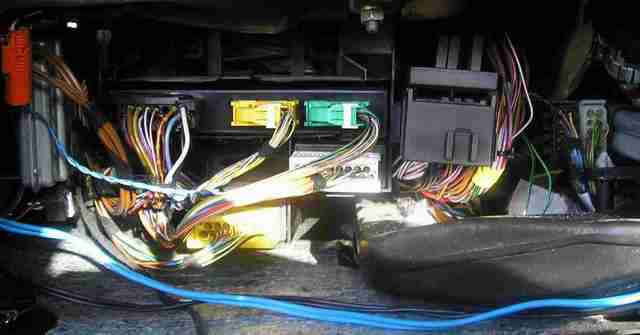
OK so heres my glovebox and there is a couple of plugs that match that description; the most obvious choice will be the one above the vent (white one in pic), and so i locate the WHITE/ red wire going into it, and to test it out i give a low current pulse +12 which should make the door locks shoot down right? well i got nothin.....? (this is all logic based so thas why i used a secondary +12v source.-of course grounnded to chasis with the -side.
I also got a bit frustrated and started just poking +12 V on pretty much all the other wires in each harness but I stilll got no door lcok/ or unlock happenin.
Please help somebody!!!??
If anyone has actually done this wiring successfully before pls just tell me exactly where the right connections are based on my pciture,
Cheers!!!
-------------
fat nick
yeh dont worry i'm an electrical engineer and know that much!!!
i've rigged up a seperate 12V source (grounded to the chasis) and i'm using my multimeter to limit current draw to 100mA which is harmless to any of the logic and will never allow nearly enuff power(1Wmax) thru to cause a major power shortage. (the only fuse that will blow will be my own cos i'm getting annoyed!!!)
-------------
fat nick
cool just once you know.
try these directions its for the UK model
POWER LOCK pin 17 + yel or pur plug, glove box
POWER UNLOCK pin 4 or pin 19 + yel or pur plug, glove box
also here is cobra's instructions which are different. hope one of these help
bmse398gbb.pdf
-------------
Why oh Why didn't i take the blue pill
Darren Power
Powermyster wrote:
cool just once you know.
try these directions its for the UK model
POWER LOCK pin 17 + yel or pur plug, glove box
POWER UNLOCK pin 4 or pin 19 + yel or pur plug, glove box
also here is cobra's instructions which are different. hope one of these help
bmse398gbb.pdf
MATE YOU ARE THE MAN! ..all i needed was that simple information and you've saved me so much f%#king about (i was halfway thru redesigning my own 5-wire 2-Relay pos trigger system just to overide the stock door control system that has evaded until now, thank god I didnt have to do same major surgery on electrics...)
Cheers again.
-------------
fat nick