96 Honda Accord horn output
Printed From: the12volt.com
Forum Name: Car Security and Convenience
Forum Discription: Car Alarms, Keyless Entries, Remote Starters, Immobilizer Bypasses, Sensors, Door Locks, Window Modules, Heated Mirrors, Heated Seats, etc.
URL: https://www.the12volt.com/installbay/forum_posts.asp?tid=70418
Printed Date: May 02, 2026 at 10:38 PM
Topic: 96 Honda Accord horn output
Posted By: copekyle
Subject: 96 Honda Accord horn output
Date Posted: January 09, 2006 at 5:33 PM
I am using an Alpine SEC-100S and I think I may have fried the siren output. If I still wanted the horn to work, could I hook the park light output into the horn wire and get the horn to honk when the siren goes off? Or will this honk my horn everytime I turn the park lights on? Any ideas how I can get this to work?
Replies:
Posted By: jmacf14
Date Posted: January 09, 2006 at 6:23 PM
first what makes you think that you fried your siren output? second some horns (most in fact) need a negative input to honk, and most parklights need a positive. it might be something simple like a bad connection for the siren. double check that you have a good ground, and make sure that you have a properly solderd joint for the positive siren output.
-------------
jmacf14
Posted By: catalin capota
Date Posted: January 09, 2006 at 7:00 PM
You could do the light flash, but you'll need to use a relay to switch polarity. You also won't be able to silently arm with the park lights connected in that way.
Like jmacf14 asked, why do you think the siren output is dead? Is it because the siren doesn't sound properly? Could be water in it..
Posted By: copekyle
Date Posted: January 09, 2006 at 9:13 PM
I think the siren output is fried because when I was installing the alarm the output showed a constant 12 volt output and then when the alarm went off, the voltage would drop to zero. I was trying to hook into the car's horn and I traced the wire all the way into the steering wheel and so I am sure I am on the right wire and it still will not work. ANY IDEAS??? (a further note, I do not have the original siren that came with this unit and that is why I am trying to hook into the horn)
Posted By: copekyle
Date Posted: January 10, 2006 at 3:42 PM
No one has any ideas?
Posted By: infinkc
Date Posted: January 10, 2006 at 4:33 PM
use a flasher with a relay to the horn
-------------
There are 10 types of people in the world, ones that understand binary and ones that dont.
Posted By: copekyle
Date Posted: January 10, 2006 at 5:21 PM
How would I wire the flasher and relay so they would work?
Posted By: infinkc
Date Posted: January 11, 2006 at 2:31 PM
 ------------- There are 10 types of people in the world, ones that understand binary and ones that dont.
Posted By: catalin capota
Date Posted: January 11, 2006 at 7:51 PM
You could always use a relay and a combination of the siren output and the light flash output.
Posted By: copekyle
Date Posted: February 28, 2006 at 7:49 PM
I have a 1996 accord and I was wondering how the horn actually works. I am trying to get an alarm output to work for the horn but it would be easier if I new how the horn actually worked! I have a wire connected to the horn wire in the steering wheel and I thought if I grounded this wire the horn should honk. It doesn't seem to work that way. Any help would be appreciated!
Thanks
Posted By: mad550
Date Posted: February 28, 2006 at 8:10 PM
Yeah the horn works through a relay, the steering wheel switch privides a small current ground, so yeah just hook your alarm/immobiliser the the wire on the colum.
-------------
WOW Sight and Sound
Maroochydore
Nothing is impossible!
Do it right the first time or don't do it at all.
Posted By: copekyle
Date Posted: February 28, 2006 at 8:19 PM
So I wired the relay today and it doesn't work. Does it matter that when the alarm is off it shows 12v and when it is engaged it drops to like 3v? I still think my siren output is fried. Anyone else have an idea?
Posted By: dualsport
Date Posted: February 28, 2006 at 10:45 PM
When you say it is engaged, do you mean that's when the siren is supposed to be sounding?
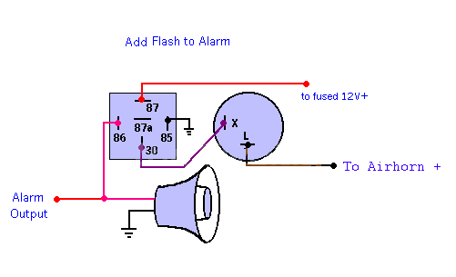
Are your measurements with the siren hooked up along with the relay as in the diagram above, or just the relay?
As long as you see a reliable change in the voltage, you can make it work even if the output driver is degraded, if you want to add some extra circuitry to it.
Posted By: copekyle
Date Posted: March 01, 2006 at 1:05 PM
Yes, when the siren is supposed to be sounding, there is a drop in voltage to about 3v. How can I make this work?
Posted By: copekyle
Date Posted: March 01, 2006 at 1:07 PM
I have done that, and when I touch it to a ground, it doesn't honk. So I'm not sure what the problem is.
Posted By: dualsport
Date Posted: March 01, 2006 at 4:03 PM
In your original setup with the siren, is the alarm output ground switching the siren? That is, the siren (+) gets a constant 12V, and then it's supposed to sound off when the alarm output going to the (-) side of the siren power pulls to ground-
As far as the horn, maybe you're tapped in directly at the horn power instead of a relay control; measure the voltage when you honk it manually to see what it does.
Posted By: copekyle
Date Posted: March 01, 2006 at 9:19 PM
In the original setup, the siren was supposed to be connected to the output from the brain (a 2A positive) and then the other wire is grounded. This is why I think that there is a problem with my siren output. It should not show a constant 12V and then drop when the alarm is engaged, right? Anyways, how would I go about wiring it, so it would honk the horn? I tried the diagram earlier in this thread and it didn't work for me.
Posted By: dualsport
Date Posted: March 01, 2006 at 9:55 PM
That seems to be a very strange way for it to fail-
Are you measuring this constant 12V coming out with the wire disconnected from everything else? And the same for the 3V you measured?
Just want to be sure it's not being affected by something you have hooked up to it, before adding on another relay driver stage-
Posted By: catalin capota
Date Posted: March 01, 2006 at 10:03 PM
Sure it is, that means it's chirping when armed... and twice to 12volts positive when disarmed.
Posted By: copekyle
Date Posted: March 01, 2006 at 10:41 PM
Yes, when I measure the voltage the wire is coming directly from the brain and there is nothing else connected.
Catalin capota- does this 12v pulse? Mine stays constant after engaged. Then when the system is set into panic mode, the voltage drops to around 3v.
Posted By: dualsport
Date Posted: March 01, 2006 at 11:32 PM
If you're sure you have the right line, and don't mind doing some tinkering, you can put this together to drive your relay- You have to make sure the voltages it's putting out is stable and not just floating, though.
I just wonder about the 3V reading you get, and still think it's strange how the signal is inverted from what you'd normally expect. If the alarm's driver output failed, I'd expect it would be just stuck at one state or not drive high, not come out backwards.
Anyway, you could try this-

Parts, not counting the relay, should be under a buck-
Posted By: copekyle
Date Posted: March 02, 2006 at 12:10 AM
WOW..... I don't mind doing the tinkering and stuff but I have no idea where to get any of those parts. I have the relay. That's about it. Where can I get the rest and can I get the exact names broken down?
Posted By: copekyle
Date Posted: March 02, 2006 at 12:12 AM
and if you don't mind, walk me through this. I'm not really even sure where the numbers (1-3) come from or stand for.
Posted By: dualsport
Date Posted: March 02, 2006 at 4:52 AM
You can get it from www.mouser.com, or try local Radio Shack- links for Mouser:
CD4001
BS170
1N4001
They have no min order, but the shipping'll cost more than the parts, so you might consider stocking up a bit.
Or, if you want only what you need, you could send me a SASE and I'll send it to ya-
Numbers define the pins on the chip; if you look at the links, they have datasheets that show a picture of it and spell out the pin positions- then just connect the dots, electrically speaking- 
|