Integrating garage opener
Printed From: the12volt.com
Forum Name: Car Security and Convenience
Forum Discription: Car Alarms, Keyless Entries, Remote Starters, Immobilizer Bypasses, Sensors, Door Locks, Window Modules, Heated Mirrors, Heated Seats, etc.
URL: https://www.the12volt.com/installbay/forum_posts.asp?tid=73215
Printed Date: April 03, 2026 at 7:10 PM
Topic: Integrating garage opener
Posted By: iceohio
Subject: Integrating garage opener
Date Posted: February 20, 2006 at 8:05 PM
I have two cars with Alert 750R alarm/remote starters in them. They each have several aux outputs that I've been trying to find a use for. I got a wild hair up my arse and decided to tear apart my garage opener remote and pull out my soldering iron... All went well until I attached it to the 3V power convertor and apparently fried the remote :( So, I've decided to go a different route.... Instead of trying to jury rig a remote, I'm considering buying another cheaper base unit, and 12v transformer and patch it into the garage opener. Then I can 'learn' the remotes and use some functions on it. I'd just rather not buy another 750R, and can't figure out how to avoid it. What I'd prefer.... Some way to mount a remote in the cars permanently that I can just wire into the 12V system. If I could find something like that, it would be easy to rig it into my alarm remote. I was able to solder connections that would have worked.. it was the power that blew up my system :( I can rig anything on the inside to open/close the garage. So the brand of the switch for activating it is irrelevent... I just need the remote transmitter to be able to be patched into my car power... Anyone know of such a beast?
Replies:
Posted By: rdlybeck
Date Posted: February 20, 2006 at 8:08 PM
Let me know if you find out. I also have the Alert 750R and would like to do this same thing.
-------------
Ryan Lybeck
"Wiring diagrams are nice but still double check with DMM"!
Posted By: Hornshockey
Date Posted: February 21, 2006 at 12:27 AM
you can usually find one of the homelink units on either ebay or at a salvage yard. They are 3 button units that run off of 12V power. They can learn damn near any remote transmitter frequency. I've got one I put in my car that control both the front gate of my apartments and my garage. Works great
-------------
Life moves pretty fast; if you don't stop and look around once in a while; you could miss it.
Posted By: iceohio
Date Posted: February 21, 2006 at 2:07 AM
Success (well so far).... I figured out why I fried the first remote. The voltage regulator I bought at Radio Shack (roughly $20) was set at 9V. Not only did I screw up the polarity, I tripled the voltage. Not good for someone who should have enough experience to at least test the voltage before connecting something as delicate as a 3V device. Anyway, I couldn't sleep, so I went and removed the remote from my wife's car, and soldered wires on the battery leads. Tested it... Works. Cool! Soldered wires onto the connection points for the #1 switch. I thought I toasted it again. The point to solder is extremely small, and I ended up delaminating it from the board. If you try this..here's some advice.. Don't use rigid wire. Use something like 22 gauge copper strand or something. Also, use a cold fusion solderer. I forgot I had one.. It saved the day. Also, if you have someone around to serve as a third hand.... do it.... So anyway I get the wires soldered... Tore apart the voltage regulator (designed to go into a cigarette lighter) and soldered wires onto it. Connected it in the Jeep and TESTED THE POLARITY again before connecting it. Added a 5A fuse, spliced it into an always hot wire. Touched the two wires together and badda bing... Garage door opened :) So tomorrow I'll add a switch to the negative side of the line, and run both sides of the wire to a ground. So when I press the switch, it will ground both sides acting like the switch closing. Then, I'll splice in a wire after the switch to go to my 750R Aux output (which is negative). So i'll either be able to press the button to close the circuit, or press the button on the remote to open my garage. After I got everything soldered, I cut out holes in the old remote casing for the wires, popped out the button (to avoid it getting pressed by accident), and will mount the regulator and remote under the dash out of sight... drill a hole for the momentary on button switch, and I have a permanent mounted garage opener that will never require batteries and always work when I press the button to activate it. In my wife's car, she has (er had hehehe) hers in a compartment that you'd press and it would (in theory) press the remote button and open the garage. The problem was it never seemed to line up right and was a pain. I'm going to fab another of these tomorrow, and pick up an extra one to leave in the garage in case we ever end up in a loaner car or something.
Posted By: dstang24
Date Posted: February 21, 2006 at 2:18 AM
Would a more simplistic way of making your remote for your alarm open your garage be to... Hook up a relay between the two contacts that are shorted together when the button is pressed? This was an idea I had for a simple 30 min rigging so I could remote start in the mornings without having to manually open the garage. Definately not as sophisticated or convenient as the way you have done it. Good work! ------------- Team Edge Audio
Posted By: iceohio
Date Posted: February 21, 2006 at 3:04 AM
I'd originally considered a relay, but realized it was unecessary since the alarm sends a ground through the aux wire. So your way would actually be a bit more sophisticated actually. If for some reason the ground doesn't work (can't see why it wouldn't) I will do exactly as you suggest. I was just trying to avoid adding the relay if possible.
Posted By: Chris Luongo
Date Posted: February 21, 2006 at 6:42 AM
I'm not familiar with the Alert brand, but will its aux output work when your car's engine is running?
On most brands of alarms and remote starters, the doorlock and trunk-release outputs are disabled with the ignition on.
Posted By: iceohio
Date Posted: February 21, 2006 at 10:43 AM
Not sure. It wouldn't matter if it didn't in my case. If it's running, I'm either in it, or the garage had better be out open already :)
Posted By: iceohio
Date Posted: February 21, 2006 at 11:20 PM
Yep. Needed a relay. Here's what I ended up doing. Went to Radio Shack and bought one of the 12V to 3V convertors. Actually it was a stepdown convertor with 3V being the lowest. Cost $21 (sucked, but at least I didn't have to worry about it). Tore it apart, soldered wires to the part designed to go into the cigarette lighter, cut the other end off. Taped it all up really well. Hardwired the wires into an always on + 12V source, and good ground under the dash. Tested the output... 3VDC -- Cool. Removed the board from the remote.... Soldered wires on to the power leads. If you do this, I highly recommend you get a cold fusion soldering iron. These contacts are PUNY, and I can't imagine how hard it would have been to not have the solder melt instantly. Anyway. I used BLACK/ Red wires so there would be no confusion about polarity later. Figured out what the contacts were I had to short to activate the garage door. Soldered a wire to each. Cut out slots on both ends of the remote casing and snapped it all back together. It had 4 wires running out of it. Two on each end. Taped it all up good so something doesn't snag a wire and pull it off or something. Tested the polarity again on the 3V supply and spliced the wires. Touched the two switch wires together.. The garage door opened. Cool. Connected wires to all but 87a on a 30A auto relay, jumpering 87 and 30 with a long black wire, then cutting it in half. Connected 85 to a constant 12V + supply, 86 to the RED / white (trunk wire) on my 750R -- I have a Jeep. No trunk. -- Connected 87 to one side of the remote switch, and 30 to the other. Hit the trunk button on the remote... Garage door opened. Cool. Drilled a hole in my console and installed a momentary button switch. Wired each end of the black wire to the switch. Pushed the button. The garage opened. Cool. Sweet success. For the sake or brevity, I omitted that I closed the garage door in between attempts ;-) It's cold here in Ohio! Joseph
Posted By: wiretapper
Date Posted: February 22, 2006 at 1:55 AM
Excellent job, Joseph! I did the same on my sport-touring motorcycle using the momentary button. Works nice when the opener is hidden away in the fairing.
Posted By: infinkc
Date Posted: February 22, 2006 at 2:30 PM
ive always just left the remote in one piece in the dash with 2 wires coming out from the switch and going to a relay from the alarm to trigger the button press. The remote battery lasts about 2 years so when it gets low i just change it out, instead of the hastle of hardwiring it all in the car. I also dont run a momentary switch to the car, i just press the alarm remote to open the door. Main reason i did it is because i park my car outside sometimes and dont want someone to break into my car and take the remote (had it happen before to get access to the garage).
-------------
There are 10 types of people in the world, ones that understand binary and ones that dont.
Posted By: D'Ecosse
Date Posted: February 22, 2006 at 6:53 PM
You can make yourself a really compact (&cheap!) voltage converter/regulator with parts available from Radio Shack - you only need three components! Get yourself an LM317T and connect two resistors up as shown in the image below - the values of the resistors will determine the output voltage based on the equation Vout = 1.25*(1+R2/R1) 
For this case, for Vout =3V (per your requirement), select resistors of 240 Ohm for R1 & 330 Ohm for R2 Using the equation Vout = 1.25* (1 + 330/240) = 1.25* (1+ 1.375) = 1.25*2.375 = 2.97V or ~3V Here's a resistor calculator link to determine the values for those who are mathematically challenged! You can eliminate the capacitors shown in the calculator schematic - they shouldn't be necessary since you're dealing a with a DC/DC conversion. Actually it will be easier to find single preferred resistor values of 470 ohm & 680 ohm which gives 3.06V - you can also either use a potentiometer for variable or just make up the resistor value with two individual resistors (e.g. 240 = 120 + 120 which are more readily available as preferred values) Resistors come in packs of 5 anyway at RadioShack so no extra cost involved, just another solder joint. For those of you with 9V remotes incidentally simply use 1.5K for R2 (with R1 of 240 ohms) to give 9V out instead of 3V ------------- Alpine DVA-7996; TME-760; SEAS Lotus Reference; Phase Linear Aliante 10Si Sub; Tru Technology C-7; Tru T2-100; D'Ecosse custom sub-box.
Posted By: iceohio
Date Posted: February 22, 2006 at 6:54 PM
They'd have a real hard time stealing my remote ;-) It's up behind the instrument panel now. That's why I really wanted to give it a power source, so I wouldn't need to ever worry about the batteries again. Even though I've become quite an expert at getting it all off, I'd rather avoid it. I just ordered an automatic headlight kit. I'm thinking that'll be the last electrocal tweak I'll do for the Jeep (beyond adding the radar and tilt sensors). Those are prewired so no hardship. I've batted around power windows. They make kits for the Jeep making the buttons look very OEM, but I am even to the point of taking the Jeep emblem off of it for fear of embarassment. I mentioned to a buddy who is a Jeep purist I added the door lock actuators and he went off the deep end. But then again he won't recognize it as a Jeep anyway because it has an AT and AC. heheh Joseph
Posted By: iceohio
Date Posted: February 22, 2006 at 7:12 PM
Outstanding! You just saved me about $15 and gave me a project :) Thanks!
Posted By: D'Ecosse
Date Posted: February 22, 2006 at 9:22 PM
No problem - very simple little project that you'll feel good about making. Probably find a dozen uses for these now!  You could consider making it on a small board (like this one) - it should fit nicely in the std battery location. ------------- Alpine DVA-7996; TME-760; SEAS Lotus Reference; Phase Linear Aliante 10Si Sub; Tru Technology C-7; Tru T2-100; D'Ecosse custom sub-box.
Posted By: dualsport
Date Posted: February 22, 2006 at 11:39 PM
You might try upping the resistance values a bit to reduce the amount of power the regulator circuit draws, since it'll be on all the time in this application.
It should still regulate properly with higher values, though there's a limit to how high you can go due to the adjustment pin current.
Just maintain the same ratio and it should work okay-
Posted By: iceohio
Date Posted: February 22, 2006 at 11:52 PM
Unfortunately I don't follow this. If I increase the resistence, either the voltage or current will need to drop. I don't want the voltage to drop much below 3V... But at the same time, I don't want a fire under the dash from a board melting either... What values would you recommend for R1 & R2 above? Basically, I'm just the yahoo at the end soldering it all together ;-) Joseph
Posted By: dualsport
Date Posted: February 23, 2006 at 12:25 AM
You could try 4.7k and 3.9k for R2 and R1 respectively-
The output voltage is then 1.25(1+R2/R1) + Iadj(R2), with Iadj about 50uA.
With the smaller resistance values, the second term is negligible, but it becomes more significant with the larger value of R2, so it doesn't drop out.
Since there's some variation in regulators for the 50uA value, you can experiment with the values or use a pot like D'Ecosse mentioned to tweak it to the exact voltage you want. The voltage needed for the remotes aren't all that critical, since a new Li battery probably sits at 3.25V so, and the remote probabably still works okay at 2.8V.
Posted By: D'Ecosse
Date Posted: February 23, 2006 at 12:47 AM
From the application notes from the device manufacturer the recommended value for R1 is typically 240 ohms with R2 scaled appropriatley. Your recommendation to select high resistance values not only goes against the design spec but also is completely unnecessary - you are talking about a total power dissipation of less than a 1/4W. No need to make this complicated with confusion over excessive power drains thatfrankly aren't an issue.
Posted By: dualsport
Date Posted: February 23, 2006 at 2:33 AM
1/4W may be normally considered negligible, but this is just adding to the power off current draw of the alarm and any other equipment using standby power.
Max recommended draw is 35mA, and having this in the power budget should be taken into consideration.
With 4mA constantly going through the resistors and the series pass regulator having to drop over 9V, it's going to be significant. Lot of wasted power with that much of a drop.
If the car is going to be driven regularly and not parked for any great lengths of time, then you can ignore the recommendations for key off power draw.
If it came down to needing that extra draw, I'd stick with the original battery power, especially since it's used only intermittently.
Posted By: D'Ecosse
Date Posted: February 23, 2006 at 12:00 PM
dualsport wrote:
...If it came down to needing that extra draw, I'd stick with the original battery power, especially since it's used only intermittently.
Interesting logic - use a couple of AA batteries will will obviously have considerable lifetime and spare the (what - 65Ah?) car battery from the 'significant' (sic!) power draw? I know you're trying to make a point here but its just not a realistic concern - sure, anything that is connected to a battery that is sinking current, regardless of how small, will ultimately drain the stored energy. But that is not unique to this device & in this case the draw is certainly small enough that it is not going to drain the battery even over a couple of weeks. We're talking about a very small current, not a 5W light bulb here! Guys who are building Led tails are using multiple regulators and there is no general concern for alarming excessive drain problems. You're just just over-stating the issue and creating needless trepidation. Anyone who is parking their car for extended periods without running should seriously consider a trickle charger anyway. I prefer the Battery Tender model myself and have a permanent connection to the battery with an extender pigtail connector in the front bumper that I can reach and connect to without even popping the hood. See it here - click
Posted By: iceohio
Date Posted: February 23, 2006 at 12:28 PM
I'd considered just jumpering the switch permanently and using the relay to add power to the circuit to turn it on/off... But the problem I could foresee is the remote losing it's memory or whatever if it sat powered off for too long. It's a Security+ unit. Maybe someday I'll add a little solar power cell somewhere to trickle charge the battery in case it's parked a long time. If it were to go dead sitting a few weeks, I can live with that, or buy a better battery or something. I'm going to go to RS later and buy the stuff to build it as in the diagram. I may even add another dash mounted female plug for plugging in my PDA and cell on long trips. Who knows? You guys have opened a lot of doors! Thanks!
Posted By: dualsport
Date Posted: February 23, 2006 at 2:01 PM
D'Ecosse wrote:
Interesting logic - use a couple of AA batteries will will obviously have considerable lifetime and spare the (what - 65Ah?) car battery from the 'significant' (sic!) power draw?
I guess you consider a constant draw of the regulator circuit the same as the case where the battery is open circuited until the remote is actually in operation. If so, that's even more interesting logic- sic- If the inefficiency doesn't bother you, it's fine.
Posted By: iceohio
Date Posted: February 23, 2006 at 2:23 PM
I didn't mean to start a war here hehehe. Given the relatively low cost to make these.. I'll make one both ways. I need to make two more anyway. The Camry has an awesome battery, so I'll use the one in the diagram for that one. For the Honda, I'll use the lower discharge one. Heck, I may even try breadboarding one without a battery... I'll rig it so the relay closes the circuit and powers the remote. Using the power as the on/off. I have a gut feeling doing that will cut into the life expectancy of the remote though (even if memory is not an issue). I used to have a heater that the switch went bad on. I just wired it to permanently on and put a switch on the power cord. It worked fine but burnt out after a couple months. Someone told me that it was probably spikes due to it getting power and instantly turning on. Capacitors not having time to charge or something... I'm no electrical genius.. Just a hack ;-) Being 3V and DC I don't think that capacitance is an issue or anything... Just the potential spike scares me. If this way worked, it would certainly be the best way. Then there's no power drain at all when at rest. Joseph
Posted By: iceohio
Date Posted: February 24, 2006 at 1:17 PM
Perhaps I missed something... I went out and bought the LM317, a 1/2W 330 ohm resistor, a 220 and two 10 ohm resistors, a board, and good solder. I wired it as the diagram indicates, only variation being I put the three resistors in series (to total 240 ohms). I found an AC to 12VDC transformer to use as a test. I cut the ends off, made sure the polarity was correct, and connected it up. My output was around 9 volts. ??? I thought I may have connected the LM317 backwards, but reversing it gave me a full 12V. I did some reviewing, and the resistors in series shouldn't be the problem. I tested the resistance across them and they can out to be about 242 ohms (within varience). Did I do something wrong?
Posted By: D'Ecosse
Date Posted: February 24, 2006 at 1:52 PM
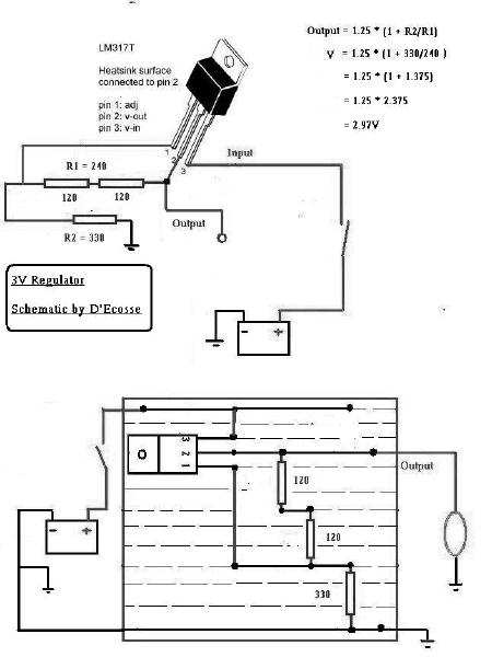
Make sure you have everything connected up properly. See above for suggested layout Recognize that the heatsink is connected to pin 2 so be sure that it not touching anything else! (Replace the 2 x 120's with your string of 220 & 2 x 10's)
Posted By: iceohio
Date Posted: February 24, 2006 at 2:12 PM
It works! I had it wired incorrectly. Your picture really helped! If you're ever around Columbus, Ohio, the beer is on me!
Posted By: D'Ecosse
Date Posted: February 24, 2006 at 2:19 PM
Congratulations!  Have fun with the next part, integrating into your GDO transmitter.
Posted By: iceohio
Date Posted: February 24, 2006 at 2:29 PM
Thanks! I let it sit powered up for a few minutes to check the heat. Resistors are cold (good) the 317 is a bit warm, but nothing to be concerned about. The voltage dropped to about 2V though. Could be my very poor wiring causing it. I'll rerig it later with solder instead of twisted wires, and check again. I have no doubt it'll be fine :) Thanks again! Joseph
Posted By: D'Ecosse
Date Posted: February 24, 2006 at 2:36 PM
If you want to optimize the heat transfer from the LM317T you can always use one of these
Posted By: iceohio
Date Posted: February 24, 2006 at 7:56 PM
Next I'll be adding a fan too ;-) I think it's ok.. but next time I go to RS I'll probably pick one up (heat sink I mean) just to play it safe. Being the consumate tweaker (hack) I decided to run a second circuit in the enclosure. There was all that extra room.... Once I get a couple more LM317Ts, I'll add them in and have a switchable power supply for anything I need to plug in... I used the resistence calculator and built a few separate strings of resistors, and added a switch to change them. I was initially going to just use a pot, but then I'd need some kind of display or something.. So I went the easy way. I simple 5 way switch. That changes the resistance to give me 0 (off) 3V, 6V, 9V and 12V (the last just bypasses everything -- The first removes the ground). Small hole in the dash for the dial, and another next to it a small power output receptical. I haven't thought far enough ahead about converting the different plugs, but I'm reasonably sure something can be found or fabricated. After I finish this, I'll be installing my 'daylight running/automatic on headlights' that just arrived, then I believe it will be time to stop rigging my Jeep for awhile. My wife thinks I've gone over the edge ;-) Thanks again all... Particularly you D'Ecosse. The diagram you created for me was above and beyond! Joseph
Posted By: D'Ecosse
Date Posted: February 24, 2006 at 8:18 PM
iceohio wrote:
... After I finish this, I'll be installing my 'daylight running/automatic on headlights' that just arrived, then I believe it will be time to stop rigging my Jeep for awhile. My wife thinks I've gone over the edge ;-)
I'm sure if you check out this forum I'm not so sure you'll be done .........  Glad to help by the way - that's a fun yet practical little project.
Posted By: iceohio
Date Posted: February 24, 2006 at 11:32 PM
Oh great... Now what would I need lights for on a Jeep? ;-) Maybe I should be looking into a more powerful alternator now, before reading the site hehe
|