Alarm connection to 5-wire door locks
Printed From: the12volt.com
Forum Name: Car Security and Convenience
Forum Discription: Car Alarms, Keyless Entries, Remote Starters, Immobilizer Bypasses, Sensors, Door Locks, Window Modules, Heated Mirrors, Heated Seats, etc.
URL: https://www.the12volt.com/installbay/forum_posts.asp?tid=76703
Printed Date: March 25, 2026 at 4:40 PM
Topic: Alarm connection to 5-wire door locks
Posted By: joneb
Subject: Alarm connection to 5-wire door locks
Date Posted: April 24, 2006 at 2:56 AM
I bought an 'old' Chemera Viam power door lock kit. And I installed it with no problems in a 1965 VW bug. I just installed an Xpress DX 350 alarm on the car and everything works except the door locks. I can't figure out the connection. The door locks do not use a relay (that I know of), there is a fused 12V+ red wire, a negative wire, the actuator motors have a blue wire and a white wire, the harness has a green, yellow, white, blue, and a red wire that connect the passenger and driver door switches. The kit was set up for either 2 or 4 doors so I clipped the blue and white wires for the rear actuators. The alarm instructions say the following: - light green wire: "connect to (-) Lock & (+) Unlock" and
- light blue wire: "connect to (-) Unlock & (+) Lock"
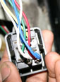
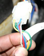
Which wires do I connect the alarm lock/unlock to? Should I add a relay? I can scan the alarm wiring diagram and send pictures of the back of the switch if it helps. The door lock kit does not come with a wiring diagram since it was so simple to connect a neg. and pos. ------------- JonEB
If it ain't fixed; don't broke it....
Replies:
Posted By: KPierson
Date Posted: April 24, 2006 at 6:28 AM
It sounds like your system is setup to lock or unlock all the doors when you toggle the state of the drivers door. If this is the case, all you have to do is worry about unlocking the drivers door, and it will do the rest. You will most likely need two relays, set up in a 5 wire configuration with 87A grounded on both relays. You can test this by tieing one of the suspected acuator leads to ground and the other tap it to 12vdc. Of course, it would be best to have the wiring information for the actuators, NOT the alarm, as the alarm outputs sound like the standard lock/unlock outputs. ------------- Kevin Pierson
Posted By: joneb
Date Posted: April 24, 2006 at 9:56 AM
So I should run leads from the alarm lock/unlock directly to the drivers side near the switch and not in the middle of the harness? The drivers side does operate all locks. I will try the two relay setup for a 5 wire system and see if that works. Can I send you some pics of the back of the switch and see if that helps you to help me? I need a diagram.
-------------
JonEB
If it ain't fixed; don't broke it....
Posted By: KPierson
Date Posted: April 24, 2006 at 10:49 AM
Post them up here!
-------------
Kevin Pierson
Posted By: joneb
Date Posted: April 24, 2006 at 6:12 PM
  ------------- JonEB
If it ain't fixed; don't broke it....
Posted By: joneb
Date Posted: May 14, 2006 at 4:43 AM
The car is a 1965 VW Bug, my alarm is a Xpress DX350 and the door locks are an older aftermarket model (no relay). I can't figure out a connection method of the two systems. Here's what I Have: Door locks: Drivers' switch has a Blue wire (motor leg to both door motors) rests at neg., +12 volts at unlock and +1.82 volts at lock. White wire (motor leg to both door motors) rests at neg., +12 volts at lock and +1.26 volts at unlock. Green wire (connects to passenger switch) rests at neg., .5-volts at lock and 1.45-volts at unlock. Yellow wire (connects to passenger switch) rests at neg., 1.35-volts at lock and .5-volts at unlock .Red wire - fused 12 volt positive lead. (Passenger switch has the black negative lead, green wire and yellow wire) Alarm outputs: Green wire (Unlock) rests at ground, pulses +12 volts during unlock, Blue wire (Lock) rests at ground, pulses at +12 volts during lock. I tried the "5-wire alternating 12 volts positive door locks" relay setup but the 87 posts reads negative when the Switch motor legs are connected to 87a. Am I connecting it wrong or is this the wrong setup to use? ------------- JonEB
If it ain't fixed; don't broke it....
Posted By: steve schofield
Date Posted: May 15, 2006 at 6:11 AM
If the motors in the door both have only two wires then the switches are simply reversing the polarity of the motor. Having no relay in the circuit means the motors will operate only while the switch is pressed and the motor will stay energized until released.If your wiring diagram shows (Motor Interrupt) use this connection to both motors and wire them the same. Be careful to connect each motor exactly as the wiring diagram shows, or one door may lock while the other unlocks! It would also be possible to wire for motor interrupt using 2 x 5 pin relays and operate with a pos or neg pulse for lock and unlock.However, you can also remove the switches from the circuit and wire for (Direct Motor Control) too, if this is an option.
-------------
Posted By: steve schofield
Date Posted: May 15, 2006 at 7:12 AM
May make more sence! Look in General Info on home page, go to Diagrams then Door locks & Window Modules. The diagram you require is: 5 wire alternating 12volts positive door locks! This works when the door motor wires rest at neg.
-------------
Posted By: joneb
Date Posted: May 15, 2006 at 11:07 AM
I tried the 5-wire positive door lock diagram but the 87 posts on the relays read negative when I connect the wires from the switch (which connected the switch to the motor) to 87a on the relay. Joneb ------------- JonEB
If it ain't fixed; don't broke it....
Posted By: dxdenis02
Date Posted: May 15, 2006 at 12:06 PM
excellent
Posted By: joneb
Date Posted: May 15, 2006 at 1:01 PM
Not Excellent, my positive leads from 87 are supposed to be fused +12 volt supply and it sparks when I try to connect it to +12 power. Hence when I check it, it reads negative. My alarm diagram shows two wires for door lock and unlock. No Motor Interrupt. The wires are: Green = connect to (-) Lock & (+) Unlock and Blue = Connect to (-) Unlock & (+) Lock. So the alarm rests at ground like the switch does. (See my posts from April 24th and May 14th, they may explain a little more) ------------- JonEB
If it ain't fixed; don't broke it....
Posted By: steve schofield
Date Posted: May 16, 2006 at 4:47 AM
That doesnt make much sense unless you have a connection wrong. Anyway, sounds like your alarm system is able to drive the motors directly. i.e without the switches! However if we are keeping them in circuit try this!
** if at any stage something doesnt go to plan let me know?**
Firstly using two 5 pin relays. Relay 1 and Relay 2. With relay 1 - Cut the Blue wire of the drivers door motor going to the drivers side switch and connect it across pins 30 & 87a.
Connect the Switch side to Pin 87a and the Motor side to Pin 30. Check your door lock switches, do they work? - they should do!
Now do the same with relay 2 Cut the white wire going to the same motor and connect in the same way. Pin 87a goes to the Switch and Pin 30 goes to the motor. Try the switches again, they should still be working!
Now disconnect the passenger side switch from passenger side door motor and connect the motor wires Blue, & White to the drivers door motor wires on the relays, each to Pin 30 and colour to colour. Check again. All okay, move on.
Both motors should now be working through the relay - Pins 30 & 87a.
We need a 12V+ to operate the motors and your alarm will not do it yet! So connect a 12V+ to Pins 87 on both relays. Fuse this supply at the same rating as the CDL Supply going to your switches!!!
Because your alarm fires 12v+ on arm and disarm > Connect Pins 85 on both of your relays to a Good Chassis Ground. 12V (-) neg.
The switches should still be operating your motors at this stage!!
Now from your alarm:
Connect your Alarm wire Blue to Pin 86 of relay 1 - 12v+ on lock to control the blue wire of the motors.
Connect your Alarm wire Green to Pin 86 of relay 2 - 12v + on unlock to control the white wire of the motors.
Good luck!
-------------
Posted By: steve schofield
Date Posted: May 16, 2006 at 7:50 AM
Hey joneb, just had a thought! Before you follow the instructions above check your relay Pin Numbers. 85 & 86 should be the Solenoid / Coil, Pin 87a & 30 Normally closed circuit and Pins 87 & 30 Normally open. Test for continuity across Pins 30 & 87 before starting. You shouldnt have any. Then test between Pins 30 & 87a if we are talking about the same relay type, this should give you continuity! There may be a diagram on the relay! Look for the circuits Normally open / Normally closed and the coil.
-------------
Posted By: joneb
Date Posted: May 16, 2006 at 8:57 AM
Thanks Steve, I can't wait to go home and try this. It makes alot of sense and I know it will work.
-------------
JonEB
If it ain't fixed; don't broke it....
Posted By: steve schofield
Date Posted: May 17, 2006 at 11:03 AM
Did we nail it?
 -------------
|