Proximity Sensor Need some advice
Printed From: the12volt.com
Forum Name: Car Security and Convenience
Forum Discription: Car Alarms, Keyless Entries, Remote Starters, Immobilizer Bypasses, Sensors, Door Locks, Window Modules, Heated Mirrors, Heated Seats, etc.
URL: https://www.the12volt.com/installbay/forum_posts.asp?tid=80497
Printed Date: May 16, 2026 at 6:09 PM
Topic: Proximity Sensor Need some advice
Posted By: noregret4life
Subject: Proximity Sensor Need some advice
Date Posted: July 19, 2006 at 2:55 PM
I have a 2005 Benz SLK350 (its a convertable) And i am planning on adding a DEI proximity motion sensor into the factory alarm or additional alarm horn. I purchased the PAC TR7 trigger, and the DEI 508D proximity module and programmed the PAC to Constant On from Pulse trigger. This part works great. However here is where i need some help: I want the proximity sensor to turn on when i lock my car from the Benz Key remote, and Turn off the sensor, when i unlock from the remote. I was able to locate a trigger for this to work. There is a gas tank actuator that locks/unlocks with the alarm activating/deactivating. The set up is 2 wires. #1 gets pulsed (+) when Lock is pressed on the key. #2 gets pulsed (+) when Unlock is pressed on the key. At rest they are both (-) When i connected the PAC TR7 programmed for Pulse > Constant, to to #1 wire. I press Lock on the Key, and the motion sensor is on. But in order to deactivate i am forced to press the Lock again since it is only connected to #1 locking wire. If i connect both #1 & #2 wires (isolated from each other) to the (+) trigger on the PAC TR7, then i will be able to Activate the motion sensor along with the alarm, and deactivate the motion sensor when unlocked. This is fine however is there a way i can connect the PAC TR7 and or other parts i may not have yet, so that the proximity sensor ONLY Turns on with the LOCK Button on the Key remote, and ONLY unlocks with the unlock button? So that in the case i hit Lock 2x it does not Activate then Deactivate the proximity sensor?
Replies:
Posted By: glantern83
Date Posted: July 26, 2006 at 5:21 PM
I belive you could use a relay... Not to sure about your hookup but a relay could allow you to add a delay of somekind to keep it from deactivating if you hit lock twice...
-KITT
Posted By: dualsport
Date Posted: July 26, 2006 at 11:01 PM
Going from your description, it sounds like the PAC TR7 just toggles from one to the other whenever it gets a pulse trigger- unless there's some other kind of input like a reset on it, it's hard to prevent it from getting out of sync with the locks without adding some circuitry.
It should be easy enough to add a logic gate that uses the proximity sensor power as one of the inputs to block the pulse when a lock pulse comes in.
For example, you could set it up so that whenever the prox sensor is powered up and the input to the gate is 12V, it prevents the lock pulse from getting to the TR7 trigger input. When the sensor is off, it would only allow a lock pulse to get through and toggle the TR7.
Posted By: noregret4life
Date Posted: July 26, 2006 at 11:06 PM
That is a good idea... How do i go about setting up a logic gate like that? Thanks.
Posted By: dualsport
Date Posted: July 26, 2006 at 11:36 PM
This should work- (note this only needs one chip, the connections shown are all in one)

The way it works is, by using the proximity sensor power as an indication of current state of the TR7, it only allows the pulse to go through if it's opposite from the current position. If it's already in the locked position, the lock pulse won't do anything, and vice versa. That way it will never get out of sync if you hit the lock button multiple times-
Don't know what the input to your toggling relay looks like, but if it's a logic input as I suspect it is, this should drive it without much trouble. If it drives a relay coil directly, then you'd have to add a transistor for more drive capability. You could just measure the resistance to see.
If the lock and unlock pulses are coming directly from the actuators rather than an electronic circuit, you should add a couple of diodes on the inputs to suppress any voltage spikes. Just connect diodes to each of the inputs, with the striped side connected to 12V.
Posted By: noregret4life
Date Posted: July 27, 2006 at 1:07 AM
thanks a lot! now i can continue this project... regards, Lenny
Posted By: dualsport
Date Posted: July 27, 2006 at 8:55 AM
Looked up the description on the PAC module you have, and it seems like it has a wide range of operational features; did you look through the manual to make sure there isn't some way it could do what you want directly? I'd look closely at it to make sure first-
If not, adding the logic circuit ought to do it. From the description, I don't think you'll need anything extra on the output to the PAC module, it's going to be a high impedance logic input itself.
On the other side, I'd add the diodes mentioned to protect the chip from voltage spikes; just connect them between the inputs and the power pin on the chip, in the right polarity.
Good luck-
Posted By: noregret4life
Date Posted: July 27, 2006 at 10:02 AM
I double checked the PAC TR7 module, and it does not look like there is a way to get it to perform as a logic gate from 2 different triggers. it has a (-) trigger wire, and a (+), so the only way i got it to work was to connect both Unlock & Lock (+) triggers with Diodes to the (+) wire of the PAC module, which then would output 12v (+) to the proximity sensor. I took a closer look at the cirucuit you designed above, excuse my lack of knowledge in the topic, but perhaps you can explain a bit further for me... Still learning here. On Pin 4 - To relay toggle input... what is that supposed to connect to? Is this an output that would connect to the alarm? or a main trigger to enable the entire circuit? I take it this is the -input to your toggling relay- you wrote of in your comment with the circuit. If it is to activate the entire circuit, then i would connect my PAC module to it so that when i turn the car off, and remove the key, the PAC gives power to the logic circuit... correct? Perhaps i explained my original post incorrectly. So here is a simplified version.... i hope: Car already has the factory built in alarm from Mercedes. Goal: attach proximity sensor with an addition siren, so that when i lock the car, proximity only turns on, and when i unlock the car proximity only turns off from the Mercedes Key remote. Proximity alarm triggers: will connect to an additional siren, Not to the Benz alarm. Triggers found: (+) pulse from Lock & (+) pulse from Unlock So would the above circuit still work based on what i described? Also, one other thing to note... The convertable roof opperates from the Key remote. Button sequence to open roof = 3 x unlock, button sequence to close roof = 3 x lock I don't think this will play too much of an issue as the proximity sensor has a built in 30sec. timer before it is activated, and the roof opens and closes in 26sec. Thanks for your help. -Lenny
Posted By: dualsport
Date Posted: July 27, 2006 at 12:46 PM
The output is just to the (+) trigger of your PAC module; just described it as a relay toggle because that's what it's doing-
Just connect it where you have your two diodes connected to.
If you need an extra delay before powering up the prox sensor on lock, it'd be easy enough to do with the logic circuit, so it'll wait whatever time you want before sending power to it. Since you have 4 seconds to spare, you can do without it for now.
Posted By: dualsport
Date Posted: July 27, 2006 at 12:54 PM
By the way, the circuit should get constant power, it's not coming from the PAC module. It has negligible power draw, so you don't have to be concerned with standby power drain.
This is simply acting as a gate for your trigger signals coming in from the lock and unlock, going to the PAC module; it's not controlling anything else.
(Independent of your alarm)
You could probably do without the PAC module with variation on the circuit, but since you've already got it, you may as well put it to work-
Posted By: noregret4life
Date Posted: July 27, 2006 at 1:25 PM
So technically, i can just use the circuit as is, with no need for the output. Because if i understand correctly, the circuit will enable, and disable the proximity sensor on lock/ulock... and the proximity sensor has the outputs for the siren already. I guess i can use the output (+) [what we have been calling the relay toggle] to power an additional alarm LED or something... am i correct ? The original use for the PAC module was to "be the logic circuit" so since it's not needed here i'm sure i can find some other use for it in the future. If not maybe Ebay it.
Posted By: dualsport
Date Posted: July 27, 2006 at 3:03 PM
Actually, you do need the PAC module with this circuit, because the output is just going to be a pulse output similar to what you're putting in with the lock/unlock inputs. This circuit just blocks the pulse from getting through at the wrong times, like when the prox sensor is powered up already, and you send in a lock input. If it wasn't blocked, you'd end up turning it back off, which is what you were having problems with.
You need to latch the power on or off (because I assume your proximity sensor isn't set up to take a pulse input to turn on and off), and that's the PAC's purpose in life. It does seem like overkill for the purpose, but if you want to do without it, you'd need a different circuit.
If the prox sensor is something more than I'm thinking it is, then it might work, but isn't the PAC simply turning the power to the sensor on and off?
Posted By: noregret4life
Date Posted: July 27, 2006 at 4:07 PM
Yeh you are right, now it seems that PAC is overkill. Yes, it is simply turning power on and off to the Proximity sensor? Perhaps a revised circuit?
Posted By: dualsport
Date Posted: July 27, 2006 at 7:50 PM
- revised circuit-

Posted By: noregret4life
Date Posted: August 21, 2006 at 2:05 PM
Ok, please note i am a totally new to all this.. so bare with me. I am about to place an order online for the parts listed in the diagram above. Now from what i was told, i will need a "Breadboard" in order to put it all together. Is this correct? Can someone help with a Part# on what i will need to mount and wire all this to? Thanks in advance.
Posted By: dualsport
Date Posted: August 21, 2006 at 3:13 PM
For something relatively as simple as this, I'd probably just get an integrated circuit socket, and just make the connections you need on the socket pins. You need at least a 14 pin socket (7 pins on each side), but if you get a larger one, you'll have room to fit the transistor on it also, which would be nicer. That way you can just plug in the components after you're done wiring up all the connections, and it allows you to replace the parts easily if there are any failures. The diodes can be soldered directly to the pins as necessary rather than using up plugging in to the socket.
This is an 18 pin one for 15 cents that should do- socket
Posted By: noregret4life
Date Posted: August 21, 2006 at 3:59 PM
Thanks dualsport. You have been a great help with this project! Just one other quick question. I have searched Mouser for 2 more parts a tiny push button switch like the one below and 2-pin headers like those on a computer motherboard so i could attach wires to the other end, and the 2 hole (female) plug that would attach to them. The distance between the pins is 2.5mm. Basically just like the one on a computer motheboard connections to the power switch. I wish i knew the technical names for all these parts, then i wouldn't have to bug you about it. If you know what its called or what i should search for would be a great help.  < mini switch.. about 5-10mm big < mini switch.. about 5-10mm big
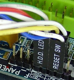 < 2 position pins so i can attach wires to the other ends. And 2 position female plug < 2 position pins so i can attach wires to the other ends. And 2 position female plug
Thanks again, Lenny
Posted By: dualsport
Date Posted: August 21, 2006 at 6:05 PM
Take a look at these switches and see if they're what you're looking for- probably figure F.
Have to dig around for the 2.5mm header receptacle; saw some that might do, but the item listing didn't show a picture of it.
|