I've searched this forum for 03 TL-S diagrams, and found some that are for 03 CL-S. is preaty close, but didn't have what I needed.
I have 2003 Acura TL-S w/o navigation.
Installing Visionguard 6000
#1 I want to hook up "Two Stage Door Locks" - first click opens drivers door only, second click opens passenger doors. Now I need to find a Driver door motor wire "to cut in with a Drivers Unlock, using a relay of course". Here is what I am talking about: 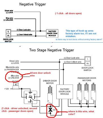
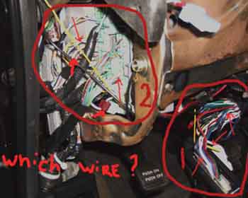
#2 Sounds cheap, but can't find a WHITE/ RED wire for trunk release at module behind glove box. I've looked everywhere in that area and no luck. There is like 10 different WHITE/ red wires. I've tried going off 03 CL-s diagram looking for white wire, still no luck. Can you guys post a picture of this wire that I can tap in, so that my trunk can be opened? I've also look for MUX here is the source: https://https://www.the12volt.com/installbay/forum_posts.asp?tid=29894 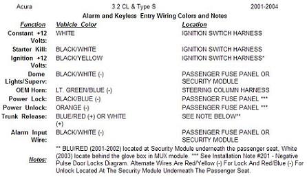
#3 where can I find wire for sunroof, factory arm, disarm, arm/disarm w/o arming factory system, tachometer wire (found 2 pin connector, blue wire at drivers shock tower with only one blue wire in it. not sure if that is it.) windows...
#4 factory alarm armed chirp, can i hook aftermarket alarm to it, and have only factory chirp?
There is a lot of TL guys out there that could use this diagram, so if anyone can help, please...
One BIG THANKS, Eugene
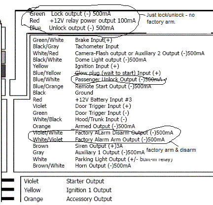
| 12volts | white | + | ignition harness | | Starter | BLACK/ white | + | ignition harness | | Second Starter | N/A | | | | Ignition | BLACK / YELLOW | + | ignition harness | | Second Ignition | N/A | | | | Third Ignition | N/A | | | | Accessory | yellow | + | ignition harness | | Second Accessory | WHITE/ black | + | ignition harness | | Keysense | blue/white | - | ignition harness | | Power Lock | BLACK/ blue | - | passenger fuse box | | Notes: Located in a blue or gray 22 pin connector in front of the passenger fuse box. Use the key switch in the passenger door to test. | | Power Unlock | orange | - | passenger fuse box | | Notes: Located in a blue or gray 22 pin connector in front of the passenger fuse box. Use the key switch in the passenger door to test. | | Lock Motor | WHITE/ red | 5wi | 18 pin grn plug, driver fuse box | | Unlock Motor | yellow | 5wi | 18 pin grn plug, driver fuse box | | Parking Lights+ | RED / black | + | 4 pin grn plug top of pass. fuse box | | Parking Lights- | RED / yellow | - | headlight switch | | Hazards | same as turn signals | | | | Turn Signal(L) | GREEN/ blue | + | steering column | | Turn Signal(R) | GREEN/ YELLOW | + | steering column | | Reverse Light | GREEN/ black | + | 2 pin brn plug below pass. fuse box | | Door Trigger | BLACK/ white | - | 4 pin grn plug top of pass. fuse box | | Dome Supervision | use door trigger | | | | Trunk/Hatch Pin | blue/green | - | 18 pin gry plg left of dri. fuse box | | Hood Pin | yellow | - | lt. blue plug below pass. fuse box | | Trunk/Hatch Release | WHITE/ red | + | passenger MUX module | | Notes: The passenger MUX module is located behind the glove box. | | Power Sliding Door | N/A | | | | Factory Alarm Arm | arms with lock | | | | Factory Alarm Disarm | disarms with unlock | | | | Disarm No Unlock | BLACK/ red to blue | - | driver door key cylinder in door | | Tachometer | blue | ac | tach test connector | | Notes: The tach test connector is a 2 pin connector near the air intake on the driver side shock tower. | | Wait to start | N/A | | | | Brake Wire | WHITE/ black | + | brake pedal switch | | Parking Brake | GREEN/ red | - | lt. blue plug below pass. fuse box | | Horn Trigger | lt. GREEN/ blue | - | steering column | | Memory Seat 1 | N/A | | | | Memory Seat 2 | N/A | | | | Memory Seat 3 | N/A | | |
 | Interface Module: | Category:
Immobilizer Bypass | Required:
Yes | Type:
Transponder | | Part #: 556HW | | Alternate Part1 #: 556UW | | Alternate Part2 #: DesignTech 20402 | | Alternate Part3 #: DesignTech 29402 | | Notes: When using the 556HW, follow the mode 2 wiring diagram. The reference wire is BROWN / yellow, data 1 wire is red, data 2 wire is blue and ignition wire is yellow/black |
|
-------------
bring back the rotary phone so i dont have to press 1 to proceed in english
visit this link and youve got the pic you requested it's th wire that is taped...
https://www.directwholesale.net/diagrams/Images.asp?ImageID=1732&link=BULLDOG
-KITT
Which wire, in which connector? Zone 1 or 2?
Thank you
zone 2 the white one with the T tap on it. (i cringe when i see T taps)
-------------
bring back the rotary phone so i dont have to press 1 to proceed in english