Adding a power door lock switch
Printed From: the12volt.com
Forum Name: Car Security and Convenience
Forum Discription: Car Alarms, Keyless Entries, Remote Starters, Immobilizer Bypasses, Sensors, Door Locks, Window Modules, Heated Mirrors, Heated Seats, etc.
URL: https://www.the12volt.com/installbay/forum_posts.asp?tid=81050
Printed Date: May 04, 2026 at 8:17 AM
Topic: Adding a power door lock switch
Posted By: bsd1
Subject: Adding a power door lock switch
Date Posted: August 01, 2006 at 5:46 AM
Car: 95 Nissan 240SX base model Alarm: Matrix RSX3.5 Factory power door lock: No My goal: to be able to use the factory power door lock switches (both LH+RH) I obtained from an SE model to toggle lock/unlock. Below is the door lock section of my Matrix RSX3.5 installed by the installer. He also added two actuators, and two 610T relays. 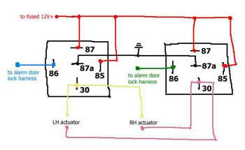
Do I have to purchase 2 additional 451M relays or can I use the existing 610Ts and connect my two wires (broken wires in blue and green) from factory door lock switch to 87a as shown in the pic below: 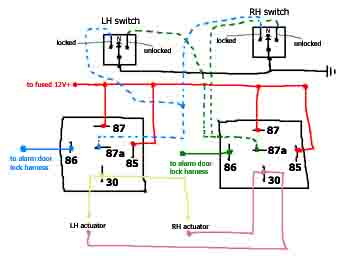 Please note that the switches use ground only and the center pin has solid ground. This wiring is like [url=https://www.the12volt.com/doorlocks/page3.asp#5w]5 Wire Alternating 12 Volts[/url] and a little identical to [url=https://www.the12volt.com/doorlocks/page3.asp#arp]reverse polarity[/url] . Please note that the switches use ground only and the center pin has solid ground. This wiring is like [url=https://www.the12volt.com/doorlocks/page3.asp#5w]5 Wire Alternating 12 Volts[/url] and a little identical to [url=https://www.the12volt.com/doorlocks/page3.asp#arp]reverse polarity[/url] .
I labeled [b]to alarm door lock harness[/b] because I am not sure it's 12v or ground. When I unpluged the door harness from the brain I got ground when probing the 86s, and got 12v when they are plugged. Anyway, I believe this isn't important to my question in the first place. What I concern the most is if I can remove the existing ground from 87a (as shown in top pic above) and run the wires from the switches (the broken wires as shown in 2nd pic above) to accomplish my goal. This thread is pretty much a followup to another thread started by [url=https://www.the12volt.com/installbay/forum_posts.asp?tid=79971&PN=7]crxratedr[/url].
Replies:
Posted By: doibuy
Date Posted: August 01, 2006 at 7:36 AM
Can't follow your diagram that well, but you should tie the lock switches in to the relays where the alarm outputs are at.
Posted By: captainzab
Date Posted: August 01, 2006 at 10:32 AM
Yes you can connect the wire from the switch directly to the blue and green wire of the clifford, but make sure you add diodes so you do not hurt the alarm.
have the bandside of the diode pointing towards the alarm (neg flow from bandside to non bandside)
Posted By: bsd1
Date Posted: August 01, 2006 at 1:25 PM
captainzab wrote:
have the bandside of the diode pointing towards the alarm (neg flow from bandside to non bandside)
I don't understand. Which is the bandside, cathode (side with the stripe) or anode (side without the stripe)?
All I know is that the switch sends negative pulse (lock or unlock). Your saying I splice a new wire to the green wire from the brain, then place a diode between this new wire and the wire from the switch?
(A) switch - (cathode)diode(anode) - door harness on brain
(B) switch - (anode)diode(cathode) - door harness on brain
A or B?
Do I connect the green wire from switch of the LH and RH together, then go thru ONE diode then to the brain or do I use TWO diodes, one for each of the two wires for each door, and a total of FOUR diodes for the whole wiring?
Is 1N4001/L diode the correct one?
When wiring, the position of the diode should be closer to the door harness on the brain or the switch?
Posted By: captainzab
Date Posted: August 01, 2006 at 2:45 PM
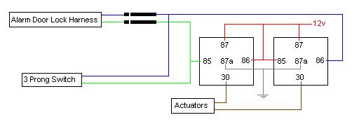
i was thinking of placing a diode on the doorlock wire of the alarm (blue and green). Put a diode with the stripe side facing the alarm.
Alarm Brain -----> [ (stripe side closest to brain) diode] ---> meet up with wire from switch --> relay
Posted By: captainzab
Date Posted: August 01, 2006 at 2:48 PM
Is 1N4001/L diode the correct one?
Yes you can use that
Posted By: bsd1
Date Posted: August 01, 2006 at 3:07 PM
The green and blue wires from the alarm door harness will be tap spliced anyway. So should the position of diode be closer to the brain or the relay, or does it matter?
You haven't answered the total number of diode required for the whole wiring process, so I guess I need TWO since the alarm locks/unlocks both door at the same time, and the door lock switches should do the same thing.
Using diode really sounds appropriate. Most other replies I have received from elsewhere simply told me to just T it in without diode at all.
You know, the factory switch costed me $70 alone, not to mention the close to $700 Matrix RSX3.5 (with all the addons), I really need to get this wiring right and not messing up my alarm.
Posted By: bsd1
Date Posted: August 01, 2006 at 3:13 PM
So, messing with 87a like shown in my 2nd pic above and at 5 Wire Alternating 12 Volts Positive Door Locks won't work or you have no experience on 5-wire scheme and unsure?
I came up with the 2nd pic cuz that's what I originally thought of the appropriate way to do it.
Posted By: captainzab
Date Posted: August 01, 2006 at 3:21 PM
Posted By: bsd1
Date Posted: August 01, 2006 at 5:32 PM
captainzab wrote:
Is 1N4001/L diode the correct one?
Yes you can use that
Thanks alot for the diagram. I will try that out and post the result here as soon as I get some diode, perhaps from https://www.radioshack.com/search/index.jsp?origkw=diode&kw=diode&kwCatid=&pg=1 ?
The first one with catalog number: 276-1101, is this the one? Without the /L, is 1N4001 okay? If I should use another type of diode, please tell me the catalog number.
Posted By: captainzab
Date Posted: August 01, 2006 at 7:38 PM
i just use the cheap 1A diode, dont know part number
Posted By: italian_virus
Date Posted: August 03, 2006 at 10:46 AM
captainzab wrote:
i am doing the exact same thing as bsd1 just that my car is a 95 honda. i have installed the actuators.. so from what this diagram is looking like i need 2 diodes and a switch ?
Posted By: captainzab
Date Posted: August 03, 2006 at 11:45 AM
yes, its that simple. But make sure its a 3 wire switch where the center is ground. I know someone out there might go to the junkyard and accidently get a weird 5 wire type that i dont know how it works.
Posted By: swamprat323
Date Posted: August 03, 2006 at 12:48 PM
can buy them here.
door lock switch
Posted By: italian_virus
Date Posted: August 03, 2006 at 1:17 PM
captainzab wrote:
yes, its that simple. But make sure its a 3 wire switch where the center is ground. I know someone out there might go to the junkyard and accidently get a weird 5 wire type that i dont know how it works.
lol funny that u said that cause i did go the junkyard and take one from a ford taurus and it has the 5 wire type and i had no idea what do to with it ;s, but thanks i have the diodes now i jus gotta get the switch
Thanks you
Posted By: italian_virus
Date Posted: August 03, 2006 at 1:19 PM
swamprat323 wrote:
can buy them here.
door lock switch
nicee thanks man ill check out crappy tire first, but knowning them they wont have so this will be my best bet haha
btw i meant Thank you on the post up above hah
Posted By: italian_virus
Date Posted: August 03, 2006 at 1:24 PM
captainzab wrote:
Is 1N4001/L diode the correct one?
Yes you can use that
i have the 1N004 is that good enough ???
Posted By: bsd1
Date Posted: August 03, 2006 at 3:18 PM
italian_virus wrote:
i have the 1N004 is that good enough ???
If you mean 1N4004, that should be the same type of diode, but with a even higher current rating, thus even better.
Posted By: italian_virus
Date Posted: August 03, 2006 at 6:04 PM
bsd1] wrote:
italian_virus wrote:
i have the 1N004 is that good enough ???
If you mean 1N4004, that should be the same type of diode, but with a even higher current rating, thus even better.
yea thats what i meant, typo hehe
Posted By: bsd1
Date Posted: August 04, 2006 at 7:18 AM
Bad news guys, I fvcked up both actuators. The RH side got burned out completely, the LH side just doesn't function anymore, seems like the motor got stuck, I had to remove the rod in order to lock the door from outside.
I then checked the brain as well as the relays, they seem to send pulse still, so I guess just the actuators are plain dead.
Now, I disconnected the door lock harness and the actuators wires completely.
Fortunately, actuators are quite cheap, I'm going to get a pair off ebay (it's expensive in local retail store, $20 each). I guess I have to put this project on hold for a few days.
Though, meanwhile, I would like to find out WHY did that happen. I don't want the new actuators to happen like that again.
Here's what I have done:
- disconnect - and + battery cable
- unplug the blue and green wire off the two relays
- use electrical tape and tape the diode tips exactly like shown in captainzab's diagram
- of course, I made sure the switch's middle pin is connected to the chassis ground. I also checked for continuity when toggling the switch to lock/unlock
- after I reconnected the battery cables I heard the actuator's noise immediately, sound like it was trying to lock or unlock the door repeatedly, without me toggling the switch
Please help..
Posted By: captainzab
Date Posted: August 04, 2006 at 9:52 AM
-use electrical tape and tape the diode tips exactly like shown in captainzab's diagram
I usually butt connect a wire & didoe, or solder the diode to the wire then tape something study behind it so the soldier cant break.
-after I reconnected the battery cables I heard the actuator's noise immediately, sound like it was trying to lock or unlock the door repeatedly, without me toggling the switch
If you knew that it was repeatedly trying to push/pull, should have unplug it. But it would seem that your switch is giving the relay ground thus switching on the relay.
I say check your switch again with your DMM. Make sure its not giving ground all the time
Posted By: bsd1
Date Posted: August 04, 2006 at 4:55 PM
I'd solder and use hot shrink tube for a permament wiring, but I was just testing the connection temporarily.
captainzab, you're the man!! That factory switch I got from junk yard wasn't quite smooth to toggle in one of the two positions, my mistake for not lubricating it in advance. So I can confirm by now that the constant ground for a few seconds killed the motor inside the actuator.
Posted By: italian_virus
Date Posted: August 04, 2006 at 6:25 PM
captainzab wrote:
yes, its that simple. But make sure its a 3 wire switch where the center is ground. I know someone out there might go to the junkyard and accidently get a weird 5 wire type that i dont know how it works.
i just checked my switch, and i do have a ground but its not center, would that affect it?
Posted By: captainzab
Date Posted: August 04, 2006 at 8:38 PM
i just checked my switch, and i do have a ground but its not center, would that affect it?
You can use it. Use your DMM to check for continuity. Press button forward and find your 2 wire that has continity. Press button backward and find your 2 wire that has continuity.
The wire that shows continuity when press forward and backward would be your ground.
Posted By: italian_virus
Date Posted: August 31, 2006 at 12:26 PM
bsd1] wrote:
captainzab wrote:
have the bandside of the diode pointing towards the alarm (neg flow from bandside to non bandside)
I don't understand. Which is the bandside, cathode (side with the stripe) or anode (side without the stripe)?
All I know is that the switch sends negative pulse (lock or unlock). Your saying I splice a new wire to the green wire from the brain, then place a diode between this new wire and the wire from the switch?
(A) switch - (cathode)diode(anode) - door harness on brain
(B) switch - (anode)diode(cathode) - door harness on brain
A or B?
Do I connect the green wire from switch of the LH and RH together, then go thru ONE diode then to the brain or do I use TWO diodes, one for each of the two wires for each door, and a total of FOUR diodes for the whole wiring?
Is 1N4001/L diode the correct one?
When wiring, the position of the diode should be closer to the door harness on the brain or the switch?
sorry to bother you guys again, im just trying this out right now, and from what it looks like it did nothing... i had both diodes connected like the diagram, now to i have to have the diodes on both sides for any of this to work out, or just on one side??.. and does it have to be a toggle switch or can it be an on and off switch?. ..
And just so you have a relative idea on how im connecting it... from the actuator comes the diode stripe side facing the actuator, then two connections one going to the switch and the other completing the connection. (using blue and green wires). i have tried to switch the connections of the wiring keeping the ground(used from the actuator) as constant .. and switching the blue and green from the switch.. and still nothing... any idea anyone??
Posted By: italian_virus
Date Posted: August 31, 2006 at 12:51 PM
captainzab wrote:
i know this may sound dumb but i have to make sure before i start splicing, i would have to cut in to my car alarms (viper) blue and green and make the connection from there.. correct ???
Posted By: italian_virus
Date Posted: August 31, 2006 at 2:25 PM
alright guys, i have also now tried from the viper brain itself, putting the cathode towards the brain,using the blue and green wires, and still nothing..
on the back of the viper brain it says that
Blue: (-) Instant Trigger Zone 1
Green: (-) Door Trigger Zone 3
There is also
Violet: (+) Door Trigger Zone 3
BUT the connection for Violet is not connected to anything ;s
help anyone??
Posted By: bsd1
Date Posted: August 31, 2006 at 3:34 PM
italian_virus wrote:
i had both diodes connected like the diagram, now to i have to have the diodes on both sides for any of this to work out, or just on one side??
Just like the diagram. Two diodes in total for the whole setup.
italian_virus wrote:
and does it have to be a toggle switch or can it be an on and off switch?
It can be virtually any momentary switch with 3 positions: (ON)- OFF - (ON). Just on and off 2 positions won't work because you'd want to lock and unlock the door, not just either one. The ground pulse is also momentary. If your switch stays in the ON position for longer than 1 second, you will blow the actuator. Therefore, it must return to center-off position.
italian_virus wrote:
i have tried to switch the connections of the wiring keeping the ground(used from the actuator) as constant .. and switching the blue and green from the switch.. and still nothing... any idea anyone??
Take out the door panel and smell the actuators, I bet they both burned out.
Nobody ever explained to me the door lock mechanism, but then I finally figured that out myself after trials and errors. I blew two actuators too.
Here's what I can tell you, don't forget:
- the actuator needs one ground and one 12v to move, both wires accept ground/12v and both wires rest at ground, because of 87a (normally closed).
- both relays must not energize at the same time. You either lock or unlock, not both. That said, the energize relay will send + pulse to the actuator (pin30 connects to pin87), the other non-energize relay will send - pulse to the actuator (pin30 connects to pin87a).
Simply, - -, or + -, or - +. If you accidentally sends a + - or - + for longer than 1 second, because of using a wrong switch, then say go bye to your actuator and it's time to buy a new one.
italian_virus wrote:
on the back of the viper brain it says that
Blue: (-) Instant Trigger Zone 1
Green: (-) Door Trigger Zone 3
There is also
Violet: (+) Door Trigger Zone 3
The blue and green I've been talking about is from door lock harness, not H1 harness.
Posted By: italian_virus
Date Posted: September 01, 2006 at 12:27 AM
Nice thanks man i apprecaite it, i will give it a shot and let you know how it goes, i already have an idea on what was wrong..andd the actuators still work, i connected them again normally and they work, soo im pretty lucky damnn haha, and just ot make sure when u mean h1 harness ur talkin about the alarm brain right?
Posted By: bsd1
Date Posted: September 01, 2006 at 5:52 AM
italian_virus wrote:
make sure when u mean h1 harness ur talkin about the alarm brain right?
Yes, H1 (12-pin) is the primary harness.
Posted By: italian_virus
Date Posted: October 16, 2006 at 1:41 PM
ive never had so many problems finding a switch haha
Posted By: souljaj
Date Posted: December 26, 2006 at 1:57 AM
Resurrecting an old thread here...
BSD1, did you ever get this to work properly? If so do you have a diagram for it? I'm trying to do the exact same thing and have already burned up 1 set of actuators. I've ordered another set and REALLY don't want to burn these up as well.
|