I got a kit from Commando Alarms - powerlocks plus alarm. On the website the description of the product is apealing saying "easy connection of powerlocks to the alarm", e-mail and telephone tech support.
Nobody answered my email for a week now , I was kept on hold for more than 2 hours in one day and the tech support voicemail is full. I cannot say i don't like the prodct but the customer service is the worst I ever seen. They are completely ingnoring me...
So... I installed the powerlocks which are working fine.. by using the key. My question would be how can I connect the alarm negative input to the powerlock module to make the system keyless? I got the above diagram (for size purposes i posted just a quarter) and I studied the relay section of the12volt but I still cannot figure it out. The front doors actuators have 5 wires, the ones for back doors two. All actuators are connected to some relay control unit.
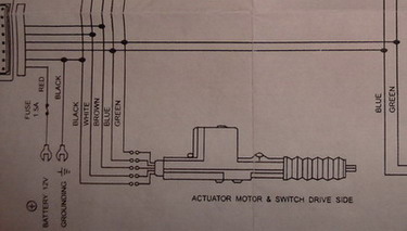
The black wire is negative all the time, the blue and green alternates + / - to open/close the doors. I have left the white and the brown wires. Can I just connect the negative input/output alarm wires to these WHITE/ brown wires or do I need additional relays (module). Do need to cut some wires? Also how can add lock/unlock through ignition (stop the engine -> unlock the doors)
Thank you in advance for your response.
Can you scan the entire diagram and post it? I would think there has to be some way to trigger the door locks via an outside source. If not, it appears if you
5-wire the blue and green on the main actuator (the one that is in the photo that has the switch built in) it would work. This would require 2 additional relays that are probably not needed though.
There must be a port somewhere on the doorlock module to use with an alarm. Do you notice anyplace on the module to plug something in, or any extra wires on the main harness? Or maybe an extra plug with 2 smaller wires on it that came with the doorlock module?
If the alarm system itself does not have an ignition controled doorlock feature it can be done with relays.
Keep us posted.
-------------
Thank you guys for your response.
The full diagram picture can be found here . The door lock module circuit board has no connection wires to the alarm, the front actuators have switches and operating manualy the front doors I can lock / unlock the car.
Also on the powerlock package says: "key operated" and there is another diagram on the box showing the extra 2 wires to connect to the alarm, only that I do not have those ones. There is no harnes or even 2 hanging wires.. nothing!
On the picture can be seen the 2 unused pins from the control unit wich should have been the alarm connection
someone correct me if I'm wrong, but doesn't the 5 wire actuator have micro switches in them. Thats what the 3 extra wires going to them are Black - Feeds the switch ground, Brown and white get the ground signal to lock/unlock the rest of the actuators when the micro switches close. So you can send a lock/unlock signal from your alarm straight to the brown and white wires. you will have to test which one locks and which one unlocks. worst case scenario you have to reverse your wires attached to the brown and white wires to get them to lock when you press lock and unlock when you press unlock.
Good Luck,
Frank
flobee4...
Yes, all of the systems I have dealt with operate in that manner, but I was hoping the manual would give a better description than what was shown in the picture. Then I looked at the full version, and it does not.
So, tcodrut, I would recommend following flowbee's instructions with one minor caveat, verify the black, brown, and white wire's functions prior to hooking anything to them. As tcodurt has mentioned, these wires are probably what trigger the relays in the control box. The black wire should always show ground, and the brown and white will alternate to ground when either locking or unlocking.
Thanx a mil.. i will try this weekend and I'll update the thread for future reference... hope I'll not burn something :))
Cheers!