2000 Neon, Viper 5900 sst
Printed From: the12volt.com
Forum Name: Car Security and Convenience
Forum Discription: Car Alarms, Keyless Entries, Remote Starters, Immobilizer Bypasses, Sensors, Door Locks, Window Modules, Heated Mirrors, Heated Seats, etc.
URL: https://www.the12volt.com/installbay/forum_posts.asp?tid=85664
Printed Date: April 18, 2026 at 4:22 AM
Topic: 2000 Neon, Viper 5900 sst
Posted By: m2736185
Subject: 2000 Neon, Viper 5900 sst
Date Posted: November 11, 2006 at 7:55 PM
Anyone ever did an alarm/Rs on a 2000 Neon before? Correct me if I am wrong here the clutch switch is negative switching so... I have 2 wires tapping into each of the 2 clutch wires going to 87 & 30 then I connect (-) starter out put and (+) fused 12 volt to relay? Also is the headlights negative or pos switched?
Replies:
Posted By: m2736185
Date Posted: November 11, 2006 at 8:11 PM
Now for the power locks, I use the following relay connection 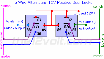
Posted By: m2736185
Date Posted: November 15, 2006 at 10:55 AM
Just bought a 5900, putting it into my 2000 Neon. I am starting with the satellite Relay harness. There is a cable that says "input from ignition, other side of key"..what do I connect this to? Also my 2000 Neon it says the Ignition 2 and accessory wire are both the same color, does this mean they are the same wire? If so i guess i connect accessory wire and ignition 2 wire to the same wire ?
Posted By: Big Dog
Date Posted: November 15, 2006 at 11:03 AM
I think you're refering to the ribbon harness. Don't cut this nor connect anything to it. All connections to the car are done from the relay pak heavy guage wires. Your car has only one ignition, the blue, to which you connect the heavy guage pink. Orange from relay pak goes to BLACK/ orange at ignition barrell. ------------- Prepare your future. It wasn't the lack of stones that killed the stone age.
Posted By: m2736185
Date Posted: November 15, 2006 at 11:32 AM
no i was refering to the heavy guage wire out of satellite relay harness. I guess that anwers my question, i wanted to know if the accessory wire also connects to the ign 2 but since there is no ign 2 i guess not. What about the green wire, the manual says ignition input?
Posted By: Big Dog
Date Posted: November 15, 2006 at 11:46 AM
It's not actually an ignition input but rather a crank wire input from the ignition switch. Your starter wire is yellow. Cut it. Connect the heavy green to the key side and the heavy purple to the engine side. ------------- Prepare your future. It wasn't the lack of stones that killed the stone age.
Posted By: m2736185
Date Posted: November 15, 2006 at 7:43 PM
thanks that makes sense, what about the remote start activation input on the main alarm harness...what does this connect to?
Posted By: Big Dog
Date Posted: November 15, 2006 at 8:17 PM
Nothing. It's used to activate the remote start by using a short pulse from a security or keyless module. You won't be connecting this in your case. ------------- Prepare your future. It wasn't the lack of stones that killed the stone age.
Posted By: m2736185
Date Posted: November 16, 2006 at 2:49 PM
I installed a few r/s before but never an entire system..so i am running into a little prob. So far I have connected all the wires for the satellite relay harness ( all the heavy guage wires for the remote start). But now its time for the alarm...I see there are 4 different door inputs? Door trigger input zone 3, multiplex unit zone 4, door trigger input zone 3, domelight supervision output , armed output. Those are all for the primary harness...do I need all those options if so I guess I would find those wires by the kick panel and I would test them by opening and closing the door?
Now for the auxilary output there is a factory alarm and disarm..since my factory alarm arms and disarm with lock and unllock there should be no use for this right?
And finally with the door lock harness, do I need to use a relay for this? Or do I just connect the wires to the unlock and lock? There seems to be 3 unlock wires do I need all 3?
Posted By: m2736185
Date Posted: November 16, 2006 at 8:36 PM
okay so I am stuck with only a few more wires to go... I just discovered there is a second acc wire in my ignition harness, online reference says there is only one but there is another wire BLACK/ white..do i connect this wire as well to the same harness wire for acc1? Now with the door trigger switch i tested the wire that it was suppost to be and I got a constant 6v when the door is opened and closed, what am I suppost to get? And finally with the door lock harness, do I need to use a relay for this? Or do I just connect the wires to the unlock and lock? I tested the wire and I get 10v when the door is unlocked...is this right
Posted By: Big Dog
Date Posted: November 17, 2006 at 10:10 AM
Sorry I didn't get back to you sooner......too busy. Don't connect the BLACK/ White second accessory. This only feeds the radio and wipers (not required for remote start) For locks, don't use the two relay 5 wire reversal method you show above. Look for a Light Green wire coming from the drivers door harness. Use the Factory ARM and Factory Disarm for lock/unlock. Relays are required for both lock and unlock. If vehicle has factory alarm, use negative trigger thru a 2.7K ohm resistor for arm/lock, and negative thru a 7.5K ohm resistor for disarm/unlock, use double pulse for unlock. If there is no factory alarm then Lock is negative trigger thru a 1K ohm resistor, unlock is negative thru a 250 ohm resistor. For the door pin input, use the Green zone 3 in the main harness. Use tan in the drivers kick for the drivers door and blue/orange in the passengers kick for the passengers door. Both wires are negative trigger and must be diode isolated. For trunk pin use the Blue zone 4 input (negative) and connect to the tab/black at the trunk light. For hood pin use the small gray hood shut down input. Install your own. You don't connect the domelight supervision nor the armed out wires of the 5900. ------------- Prepare your future. It wasn't the lack of stones that killed the stone age.
Posted By: m2736185
Date Posted: November 18, 2006 at 11:19 AM
thanks for the reply, let me make sure i got this right.. so I use a relay for the door locks so i solder the wiring coming OUT of the relay not before to a resistor then solder the other end of the resistor to the door unlock wire? And how would I use double pulse? 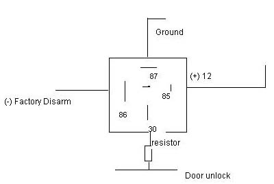
Now for the door pin I run a wire from the blue/orange then one from the ran connect a resistor to each of the ends then connect the other end to the alarm input? I can use a 3 amp resistor right?
Posted By: m2736185
Date Posted: November 19, 2006 at 1:11 PM
btw what resistors am I using, (3/4w, 1w?) and what tolerance, 5%,`%?
Posted By: daxton
Date Posted: November 19, 2006 at 11:42 PM
does anyone have the pdf install manual for the 5900? wanted to have a read through it, but can't find online.
thanks
dax
Posted By: Big Dog
Date Posted: November 20, 2006 at 8:20 AM
It's exactly the same as this https://www.the12volt.com/installbay/file.asp?ID=430 execpt that it uses a different antenna and transmitter frequency. Functions on TX are the same. ------------- Prepare your future. It wasn't the lack of stones that killed the stone age.
Posted By: Big Dog
Date Posted: November 20, 2006 at 8:22 AM
m2736185, your doorlock diagram is correct. One relay for arm/lock and one for disarm/unlock. 1/4 watt 10% resistors are fine.
-------------
Prepare your future. It wasn't the lack of stones that killed the stone age.
Posted By: m2736185
Date Posted: November 23, 2006 at 1:44 AM
For the door locks, there is no Neg Green lock unlock, i think the door locks=5 wire door lock
Posted By: Big Dog
Date Posted: November 23, 2006 at 8:12 AM
In that case it's ORANGE / black and pink/black - 5 wire reversal. Follow the diagram you showed us in your second post. Be sure that the tracers are black - not purple, because under certain lights they can look similar.
-------------
Prepare your future. It wasn't the lack of stones that killed the stone age.
Posted By: m2736185
Date Posted: November 23, 2006 at 4:50 PM
Do you know where the wires are located? I cut a orange black wire and a pink violet wire in the kick panel and it stopped the back door locks from working. I guess i need to find the wire going from the switch to the motor.
Posted By: Big Dog
Date Posted: November 24, 2006 at 7:20 AM
m2736185 wrote:
For the door locks, there is no Neg Green lock unlock, i think the door locks=5 wire door lock
I'm sorry to be a pain about this but I'm convinced you can do it multiplexed. Do you have a doorlock switch on the driver's door? Does it lock and unlock all? Does the key in the driver's door lock/unlock all? Do you have an OEM alarm? Then it's a single wire multiplex and the green wire has to be there. It runs from the driver's door to a module in the center dash above the heating controls. The pink/purple wire you cut is the "unlock" motor wire for three doors and will not control the driver's door. That's why I mentioned "black tracer" not purple. BTW, it also runs up to that module in the dash. ------------- Prepare your future. It wasn't the lack of stones that killed the stone age.
Posted By: m2736185
Date Posted: November 24, 2006 at 5:09 PM
Yes, I believe you are right. The green wire I was testing out for the door harness wasnt the same as the one at the switch. The green wire at the switch is (-) it reads 7.39 V constant, with unlock it reads11.24V and Lock 11.86V. So i guess this is the wire I am looking for. I was unable to find resistors anywhere except radio shack but they didnt have the ones I need... so i ordered 2.7K Ohm 1/2W Carbon Film Resistor (Pack of 100) & 7.5K Ohm 1/2W 5% Carbon Film Resistor (Pack of 100). These should do the job right? So i guess I just solder these to the end of the wire coming from 30 on the relay
Posted By: m2736185
Date Posted: November 26, 2006 at 6:17 PM
Hi,
I need help programming my Viper 5900, after finally contecting all the wires it seems like only the basic alarm functions are working. At first I tried to program it on my own by following the intsructions on the manual, but it was arming without locking so i decided to select channel 14 which automatically resets it to default settings. Now here is my problem. Witht he default setting the lock and arm works the way its suppost to..but unarm/unlock works like this. I press unlock and it unarms I then need to press it twice afer it unarms to unlock. Then there is a prob with the Aux which is suppost to operate the trunk hatch, when i press it and hold down on it it goes into panic mode. Then with the remote start..nothing happens at all. Any suggestions?? thanks
Posted By: m2736185
Date Posted: November 26, 2006 at 10:54 PM
Okay the Trunk pop works, stupid mistake one of the last fuse holders I forgot to put a fuse into. But i still have a prob with the remote start. It is proly because I have a sentry key system...but i had the key in the ignition and still nothing. Also which setting would disarm and unlock with one push of the unlock button?
Posted By: m2736185
Date Posted: November 27, 2006 at 12:20 PM
I checked all fuses and tested all the heavy gauge wires from the satellite relay, they are all good. I probed the (-) starter wire coming from the ribbion harness while pressing the start button and got nothing. Maybe there is somethign wrong with the ribbion harness/port?
Posted By: Big Dog
Date Posted: November 27, 2006 at 3:04 PM
The ribbon harness is all negative out except for the yellow which is positive ignition to the brain when you turn the key to ignition. Did you program the tach? Make sure brain sees hood as closed, brake not pressed and that there is a ground signal input on the BLACK/ white neutral safety input wire. ------------- Prepare your future. It wasn't the lack of stones that killed the stone age.
Posted By: m2736185
Date Posted: November 27, 2006 at 3:34 PM
no tach. I thought the hood was the problem so I cut the hood wire just to test it. My car is manual so there is no neutral safety wire.
Posted By: m2736185
Date Posted: November 27, 2006 at 6:42 PM
ah I see, great well the R/S works now I missed the part where the NSS wire needed to be grounded. It grinds for about .2 seconds but i guess it wont do much harm. Now I just seem to have one issue left, my unlock and lock is connected to factory arm and factory rearm. The unlock needs to be set to a double negative pulse but i cant seem to find that option in the features menu...does this mean I will need to connect it to the unlock/lock harness?
Posted By: m2736185
Date Posted: November 28, 2006 at 11:23 PM
Well the easiest part of the installation doesnt seem to be going as planned. I got the DEI 555C, the directions were as easy as can be. Ground the wait to start input and the (-) wire from the chip harness, Insert one key for 8 seconds then the other untill the security lamp comes on which it did. I the took the key out placed the chip 1/2 an inch from the keyhole and pressed the auto start button. The security lamp began to blink then it stayed lite for 3 seconds and beeped like its suppost to...so i assume the chip was programmed. I placed it in every configeration I could, around the key cyclinder,near the imobilizer, near the ribbon harness and still nothing. They car would cut off right after it started. I then tried the key in all different positions and the same thing would happen, the car doesnt even remote start unless the key is in the run position.
Posted By: Big Dog
Date Posted: November 29, 2006 at 9:44 AM
Use this procedure to program your 555C : https://www.the12volt.com/uploads/files/555C_Alternate%20procedure.pdf This is because the Neon rerquires a final acc wire which isn't fed during remote start. ------------- Prepare your future. It wasn't the lack of stones that killed the stone age.
Posted By: m2736185
Date Posted: November 29, 2006 at 2:23 PM
I have tried the foil method and the key wouldn program at all. The light would continue to blink slowly. I guess I will try it again. If that doesnt work I guess I can always try jumping the second accessory wire. The instructuions you linked me to states that you reconnect the blue wire to the remote start...dont you only ground this wire during programming process then its dissconnected?
Posted By: Big Dog
Date Posted: November 29, 2006 at 2:33 PM
The blue wire of the 555C needs to see ground out during remote start. The Neons have a RED / white second acc which needs to be triggered for the 555C (or any transponder module) to learn - this is the idea of using the oem key and tin foil. This RED / white is not required for remote start however. Do you have two different keys? One key twice will not work. Wait up to a minute while programming the 555C. ------------- Prepare your future. It wasn't the lack of stones that killed the stone age.
Posted By: m2736185
Date Posted: November 29, 2006 at 7:14 PM
Well this gets better, is this odd or is it just me? Here is the latest progress. So they key programmed but... it still cuts off with R/S. It cuts off if I try to remote start with the key covered in tin foil, but as soon as I put the chip near the ignition it stays on. So I connected the blue wire to a constant ground so its always on then I go to start it with the key without the foil and it cuts off so im like whats going on here. As soon as i removed the ground from the chip it starts with the regular key. For some reason I dont think its going to start unless a key is in the run position. Has anyone ever heard of this? to test this out I started the car with the R/S and quickly put the key covered in foil into the run position and it stayed on.
Posted By: Big Dog
Date Posted: November 30, 2006 at 11:46 AM
I'm just a little confused. The blue of the 555c should be connected to a "ground when running" output of the remote starter. The relay of the 555c should only activate when remote started. Let me explain how the 555c works which will help you understand what it's supposed to do. The 555c is actually a pellet taken from a key. There is a winding around the pellet which shunts (blocks) the RF at all times except when the blue wire is activated at which point the relay opens the shunt winding allowing the RF of the pellet to send its signal to the car. It's that simple. ------------- Prepare your future. It wasn't the lack of stones that killed the stone age.
Posted By: m2736185
Date Posted: November 30, 2006 at 2:50 PM
Yes i am aware of how it works, but what I am saying is it only works when there is a key in the ignition. If i start the car with the remote and quickily insert the foiled wrapped key the car works fine. Keep in mind if I try to start the car with the foil wrapped key without the pellet it cuts off. So what I was trying to say is the chip is not working unless there is a key in the ignition. If i try to remote start the car with the key without foil in the ACC Position it will not work either unless the key is in the run position.
Posted By: Big Dog
Date Posted: November 30, 2006 at 2:59 PM
Stupid question: Did you connect the red of the 555c to acc or 12V battery?
-------------
Prepare your future. It wasn't the lack of stones that killed the stone age.
Posted By: m2736185
Date Posted: November 30, 2006 at 3:31 PM
red wire is connected and fused to constant +12
Posted By: m2736185
Date Posted: November 30, 2006 at 7:12 PM
Maybe the second accesspry wire needs power?
Posted By: m2736185
Date Posted: November 30, 2006 at 10:49 PM
Well I tired jumping the second ACC wire and a few others but nothing . I know the chip is programed because I wrapped a key in foil and it would cut off if i tried to start it with the key but as soon as i put the 555C chip near the ignition it starts. Also If i remote start just before the car starts I would put the key wrapped in foil to the run position and the car would stay running. Keep in mind the will not start unless the key is in the run position with or without the chip.
Posted By: m2736185
Date Posted: December 01, 2006 at 10:16 PM
well prob solved....i thought you just had to set the jumpers to no tach i didnt know you also had to program it to voltage. well thats done now. Now 2 more things and i should be set. Right now I have the ground for the 555 module connected to my defroster output, but I want to connect it to my defroster so what am I going to use to ground it when the R/S engages? And Second I have my lock and unlock connected to my (-) factory arm and dis arm which i dont think has an option for 2 negative pulses which is what I need to unlock...will i need to hook it up to the unlock harness?
Posted By: Big Dog
Date Posted: December 04, 2006 at 7:27 AM
There was a 4 pin connector (pink., purple, orange, blue) in the box which connects into the XCRS relay pak. The blue is the "ground out" wire required for the 555C. Unless I'm mistaken, you've built a multiplexed system which has two relays and resistors for arm/lock and disarm/unlock. If that's so, for locks, the 5900 can be programmed for double pulse unlock. Don't forget to also connect the GREEN/ black disarm of the 5900 to activate your unlock/disarm relay so it can automatically disarm before remote starting. ------------- Prepare your future. It wasn't the lack of stones that killed the stone age.
Posted By: m2736185
Date Posted: December 05, 2006 at 10:41 PM
Thanks for all your help Big Dog. Everything works great now. Not exacly 1 mile or 1/2 a mile but im happy with the range and the R/S now that is getting colder.
|