I'm having trouble with the door locks working. I originally though that adding the green and blue wires to the brain at points A and B was the correct method of wiring. SO I spliced in here, I connected each point to ground and heard a faint click on the lock/unlock relay box. Using My DMM i found the GREEN / WHITE and GREEN/ red wires have voltage at rest and 0 volts when applied. Do I need to install a diode for each wire between the switch and the connection point for the alarm? Or between the conenction points and the relay box? Also how does the 2nd unlock output factor in? My system takes 2 unlock toggles on the switch to unlock all doors. So how can I set the remote to hit disarm once and the drivers only unlock, and hit it again to unlock the rest of the doors? Any help is appreciated. Here is the schematic of my door locks with the points I tapped into.:
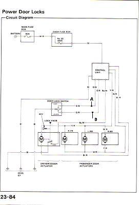
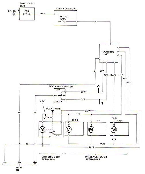
Sorry hers a better picture.
Wire your relays like the diagram, EXCEPT put ground to pin 87 on BOTH relays, and pretend is says negative door lock wire at the bottom. What you have in your diagram, looks very over engineered......
| POWER LOCK | GREEN / WHITE (TYPE B) | IN DRIVERS KICK PANEL | |
| POWER UNLOCK | GREEN/ RED (TYPE B) | IN DRIVERS KICK PANEL | |
-------------
Wouldnt grounding at points A and B do the same thing to test it? Which is what I did and they didnt unlock or lock. I was hoping to use the relays in the control box. The diagram is from the book to my car, so it shows everything.
Build your self a couple of relays like in the diagram, paying attention to the extra notes I wrote. Find the lock and unlock wires in the drivers kick panal
Lock is BLACK/ red....could also be GREEN / WHITE.
Unlock is BLACK/ white....could also be GREEN/ red.
Hook them up and your done. Just like in the diagram. You are putting way to much thought into this....it's a very basic connection, and very basic relay wiring.
I am not looking at your diagram....I'm old and it's very hard to read, so I don't know about points A, and B. Sorry. Do it this way and be done! No more guess work.
-------------