viper 150 esp/xcrs 500m, 87 bronco
Printed From: the12volt.com
Forum Name: Car Security and Convenience
Forum Discription: Car Alarms, Keyless Entries, Remote Starters, Immobilizer Bypasses, Sensors, Door Locks, Window Modules, Heated Mirrors, Heated Seats, etc.
URL: https://www.the12volt.com/installbay/forum_posts.asp?tid=91560
Printed Date: March 21, 2026 at 8:19 PM
Topic: viper 150 esp/xcrs 500m, 87 bronco
Posted By: slawson2000
Subject: viper 150 esp/xcrs 500m, 87 bronco
Date Posted: March 11, 2007 at 6:40 PM
I have a Viper 150 ESP that I would like to install. I have searched around and found two install manuals for the main module, one for the 150ESP and the other for the 552 Series. My problem is that the kit came with a XCRS 500M relay satellite and I can not find anything in the manuals that links the two together. I have also searched for an install guide for the XCRS without any luck. The XCRS has a 4 pin and a 7 pin hookup that is still a mystery. Are these compatible items? Can anyone point me in the right direction? Thanks in advance.
Replies:
Posted By: mobilecustoms
Date Posted: March 11, 2007 at 6:45 PM
it is not compatable
you need the hcrs
-------------
Posted By: slawson2000
Date Posted: March 11, 2007 at 7:00 PM
Fudge.... I thought relays were all basically the same. Where could I obtain a hcrs? Is there a specific one I need? I am still confused, because I do not see hcrs listed in the manuals either. How would those get hooked up?
Posted By: slawson2000
Date Posted: March 11, 2007 at 8:07 PM
After a lot more searching and a little more reading I have a couple other questions. Is the hcrs basically three independent relays, if so, does anyone know what size? Is the xcrs basically a four in one relay? If so, couldn't it be wired to act as a hcrs? An xcrs wiring diagram or directions would really help about now.
Posted By: dirtjumper895
Date Posted: March 11, 2007 at 8:42 PM
Go to this page. https://www.the12volt.com/installbay/downloads.asp?srch=all&term=791xv Click on 791xv install manual. There should be the wiring diagram for the xcrs in the last page. Hope it helps.
Posted By: JWorm
Date Posted: March 11, 2007 at 9:40 PM
The newer style relay pack (with a 7 pin ribbon cable) can easily be made to work with an older style unit that had the 5 pin ribbon cable and 4-pack of relays.
Do you have a 5 pin harness that can plug into the viper 150 and do you have a 7 pin harness that can plug into the relay pack? All the wires in those plugs should be skinny wires...about 18 gauge. If you have both of these plugs...the rest is easy.
5 pin harness ---- 7 pin harness
purple ---- purple
orange ---- orange
pink ---- pink AND pink/white
yellow ---- yellow
red ---- probably not needed...but may need to be hooked up to +12v
Not needed ---- blue
H1/1 orange ---- ORANGE / black
Posted By: slawson2000
Date Posted: March 11, 2007 at 11:26 PM
I was thinking along those lines. Thanks. Another question is that there is a 4 pin output from the xcrs - are those the same as the ones out of the esp150? What about the larger green wire (key side starter wire)? What is it? And while I am at it, I want to also hook up (if possible) a 530T (I think) to my rear window to allow for remote up/down capabilities. What would be the best way to do that?
Posted By: Twelvoltz
Date Posted: March 12, 2007 at 7:21 AM
1) The 4 pin output is an extension of the ribbon cable wires. This makes it easier to add things like extra ignitions/accessories/etc. Since you are hooking up to the ribbon cable itself you can get any extra ignitions via the ribbon cable without the need for the extra 4 pin plug.
2) The larger green wire is 1/2 of the starter kill/anti-grind circuit. If you decide you want the starter kill/anti-grind circuit this wire connects to the key side of the starter wire that you cut, and the purple goes to the vehicle side of the cut starter wire.
3) What kind of vehicle are you putting this in? Make/Model/Year
-------------
Installer, IT support, and FFL. I need less hobbies.
Posted By: slawson2000
Date Posted: March 12, 2007 at 9:12 AM
It is going into an '87 Bronco.
Posted By: Twelvoltz
Date Posted: March 12, 2007 at 10:29 AM
Does that truck have a switch up front that controls the window? If it does you should be able to hook your 530T in right there. If it does not, and is only controlled using the key in the rear door you would have to run your wiring into the door.
-------------
Installer, IT support, and FFL. I need less hobbies.
Posted By: slawson2000
Date Posted: March 12, 2007 at 10:57 AM
There is a switch in the dash that works when the accessories are on or there is a key in the tailgate that works all the time. I am thinking I could tie it in at the dash with the unit getting power from somewhere else. How does the 530T operate? Is it a momentary switch? Timed? Load sensing? It just keeps getting better. I am trying to figure out what type of door locks I have. I thought I had it, but I guess not. If I look at the factory schematics it looks like there is a ground loop that goes through the switches and motors while it is inactive. Then when a switch is activated (unlock), the ground is broken in that spot and a 12+ is introduced going to the motor, back through the other switch (lock) which at rest is still grounded thereby completing the circuit. I thought originally it was a type a, but it seems that it would just ground out. I think it is a type c (reversing polarity). From the ESP150 manual it looks like you loose the use of the factory switch when this is installed. - is that correct? I'd like to double check before I dive into this side. Here is a Ford factory diagram. 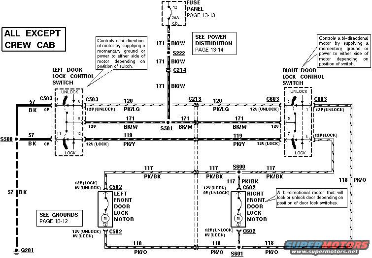
Posted By: Twelvoltz
Date Posted: March 12, 2007 at 2:12 PM
Your truck is indeed a 5-wire for door lock control, if you take a look at the 5-wire diagram you can see that when the relays are not active and the wires you cut are connected via pins 87a and 30.
The 530T uses resistance to know when the motor has completed it's travel. Reading through the installation manual explains this on page 6. ------------- Installer, IT support, and FFL. I need less hobbies.
Posted By: slawson2000
Date Posted: March 12, 2007 at 2:37 PM
Hmmm. I think I got it. So I need to pick up two relays to wire this in, I assume they should be rated for at least 30 amps each? I have not picked up a 530T yet, it'll probably be a few months down the road.
Posted By: slawson2000
Date Posted: June 24, 2007 at 2:48 PM
Well, this is where I started. https://www.the12volt.com/installbay/forum_posts.asp?tid=91560&KW=esp150 Now I am finally diving into the install tomorrow (Monday) and am hoping that a couple knowledgeable people will be around to help. Any install suggestions would be helpful. Drop the dash, don't drop the dash, etc. Mostly I think I will need wiring advice or clarification. Thanks in advance.
Posted By: slawson2000
Date Posted: June 24, 2007 at 6:06 PM
So here begins the questions... Ignition. I am looking to see what ignition circuits need to be hooked up on the truck to make this work. So far I am pretty sure I need to run: xcrs Pink to vehicle RED / LT Grn - This should power up the charging circuits. ? xcrs Pink / White to vehicle WHITE/ lt blue - power to coil ? I have no idea but I want the A/C/Heater circuit on truck - that is a must. Should I use the xcrs for that? Does hooking up ESP150 H1/1 orange to xcrs orange work this relay? ? Cut the truck RED / lt blue starter circuit and the starter side goes to xcrs purple and the key side to xcrs green. Thanks
Posted By: slawson2000
Date Posted: June 25, 2007 at 2:45 PM
Anyone? So far so good. The unit is fired up and the door locks, flashing lights, and horn works. I think I want a soft chirp siren though. Next comes the remote start.... Anyone?
Posted By: slawson2000
Date Posted: June 26, 2007 at 11:36 AM
Lets get a little more specific... There is a BROWN / pink wire coming from the ignition switch that I guess is for the run output for the engine. Does anyone know what this feeds? Is it kooked up into the RED / lt green ignition wire somewhere down the road. Do I need to hook this to Ing2 output of the xcrs?
Posted By: JWorm
Date Posted: June 26, 2007 at 12:41 PM
Your post are very difficult to understand which is probably why nobody is responding to your thread. I'll give it a shot though. I also understand you have a relay pack from a newer system and are trying to get it to work with a unit that used the older style relay pack. Have you tested the BROWN / pink wire? Is it hot when: the key is off? the key is in the run position? the starter is cranking? That wire is not listed in the wiring diagram I have. If I remember correctly, it is an accessory wire that you don't need to connect. slawson2000 wrote:
So here begins the questions... Ignition. I am looking to see what ignition circuits need to be hooked up on the truck to make this work. So far I am pretty sure I need to run: xcrs Pink to vehicle RED / LT Grn - This should power up the charging circuits.
Correct slawson2000 wrote:
? xcrs Pink / White to vehicle WHITE/ lt blue - power to coil
I have no idea what you are trying to say above. slawson2000 wrote:
? I have no idea but I want the A/C/Heater circuit on truck - that is a must. Should I use the xcrs for that? Does hooking up ESP150 H1/1 orange to xcrs orange work this relay?
The H1/1 orange wire has nothing to do with the accessory relay. Do you have the 5 wire harness that plugs into the remote start brain? It will have a red, yellow, pink, orange and purple wire. Also, do you have the 7 wire harness that plugs into the relay pack? It should have a red, pink, pink/white, orange, violet, ORANGE / black and blue wire. slawson2000 wrote:
? Cut the truck RED / lt blue starter circuit and the starter side goes to xcrs purple and the key side to xcrs green.
At least you got that correct.
Posted By: slawson2000
Date Posted: June 26, 2007 at 1:43 PM
Sorry for the confusion... just trying to get it done before I bake - it is supposed to be 108*+ today. BROWN / pink is hot in the ignition/start position. I figure it may be for the ignition accessories like the a/c. I hooked it up to the XCRS pink/wht (ignition 2). BROWN / pink is not in anything I have either, but is does come off the Ignition 2 spot on the ignition switch. There are a couple Accessory spots on the ignition switch as well, but I am not doing those as I do not care if the radio and wipers work when no one is in it. xcrs Pink to vehicle RED / LT Grn - got it thanks xcrs Pink / White to vehicle WHITE/ lt blue - power to coil - Never mind, it connects to the RED / lt grn down the harness. I have the 5 wire harness and the 7 wire harness. Currently i am wiring as you indicated previously 5 pin harness ---- 7 pin harness
purple ---- purple
orange ---- orange
pink ---- pink AND pink/white
yellow ---- yellow
red ---- probably not needed...but may need to be hooked up to +12v - I a not hooking up at all.
Not needed ---- blue
H1/1 orange ---- ORANGE / black Oh, and got the starter circuit together. I have everything else in and am getting ready to try it out. Am i ready? Did I screw up or forget something? Thanks for the help and patience.
Posted By: JWorm
Date Posted: June 26, 2007 at 3:10 PM
Is there a thick grey / YELLOW in the ignition harness? That will probably need to be hooked up as well. It will have to do with the heat/AC.
What did you connect the BLACK/ white neutral safety input of the Viper to?
Everything else looks good.
Make sure you try to learn the tach signal before trying to remote start.
Posted By: slawson2000
Date Posted: June 26, 2007 at 4:25 PM
Nothing is hooked to the thick grey/yel wire. The Grey / YELLOW drives the wiper motor mostly. I got it fired up. Still need to learn the tach, not sure how to do it, but then again do I because it already runs? Still need to go though the programming. I perfer everything to be active. I do not want it to do anything unless I tell it to. The BROWN / pink must run the a/c, because it is working on the remote start. The BLACK/ white safety hooked to the switch and then to the ground. The tap for the start wire is directly off the ignition switch and the neutral safety is down current, so I should be in good shape correct? Still testing. The anti-theft is working, locks, lights, horn as well, brake shuts it off. Still need to do hood pin, redo one set of wires. I think I have the xcrs purple and green backwards. If I connect them the starter works, apart it does not. I'd like to have the anti-grind. Mount the shutoff switch and tuck up the wires securely.
Posted By: slawson2000
Date Posted: June 26, 2007 at 6:26 PM
Had the start wires backwards - now it works. Anti grind works. Hood pin works. Dome light works. I think I have it down. Still have to teach the tach and tuck up wires. All I am not sure of is the safety switch (BLACK/ white wire and switch), but I think it is right.
Posted By: JWorm
Date Posted: June 27, 2007 at 8:50 AM
The BLACK/ white wire is fine the way you have it.
Assuming you have connected to a correct tach signal....
Start truck up with key, then hold valet button in...after a second the l.e.d. will light up....release valet button. L.e.d. will shut off and you are good to go.
Posted By: slawson2000
Date Posted: June 27, 2007 at 10:26 AM
Thanks for the BLACK/ white wire info. Got it, I'll set the idle today. What does it control or monitor? How? Should this be done with the engine hot or cold? BTW, thanks for all the help.
|