I just got this Keyless entry system from EBay for my 91 Toyota Celica ST. The instructions were not clear on which wires from the module need to go to the Power lock motors. The motors have two wires one green and the other Blue any idea would help..thanks in advance..
-------------
ETO
I doubt this unit has built in relays, so you'll need to wire some up.
| MODEL | YEAR(S) |
| CELICA | 1990 -1993 |
| KEY | T-HARNESS | IMMOBILIZER |
| N/A | N/A | N/A |
| PART | COLOR | LOCATION |
| 12 VOLT CONSTANT | WHITE (+) or BLACK RED (+) | IGNITION SWITCH HARNESS |
| STARTER | BLACK/ WHITE (+) | IGNITION SWITCH HARNESS |
| STARTER 2 | | |
| IGNITION 1 | BLUE/RED (+) | IGNITION SWITCH HARNESS |
| IGNITION 2 | BLACK/ ORANGE (+) | IGNITION SWITCH HARNESS |
| IGNITION 3 | N/A | |
| ACCESSORY /HEATER BLOWER 1 | GRAY (+) | IGNITION SWITCH HARNESS |
| ACCESSORY /HEATER BLOWER 2 | N/A | |
| KEYSENSE | N/A | |
| PARKING LIGHTS ( - ) | LIGHT GREEN (-) | @ STEERING COLUMN HARNESS |
| PARKING LIGHTS ( + ) | DARK GREEN (+) | IN DRIVERS KICK PANEL |
| POWER LOCK | BLUE/BLACK (TYPE B) | IN DRIVERS KICK PANEL |
| POWER UNLOCK | BLUE and GREEN (TYPE B) Use both, See NOTE *1 | IN DRIVERS KICK PANEL |
| DOOR TRIGGER | RED / WHITE (-) | @ FUSEBOX |
| DOMELIGHT SUPERVISION | USE DOOR TRIGGER, Requires Part #775 Relay | |
| TRUNK RELEASE | N/A | |
| SLIDING POWER DOOR | N/A | |
| HORN | GREEN (-) | @ STEERING COLUMN HARNESS |
| TACH | BLACK or WHITE/ BLUE | @ CHECK CONNECTOR See NOTE *2 |
| WAIT TO START LIGHT | N/A | |
| BRAKE | GREEN / WHITE (+) | @ SWITCH ABOVE BRAKE PEDAL |
| FACTORY ALARM DISARM | N/A | |
| ANTI-THEFT | N/A | |
| EXTRA INFORMATION |
| NOTE *1 WHEN CONNECTING FOR UNLOCK, YOU MUST USE BOTH WIRES AND DIODE ISOLATE, to connect, See DIAGRAM NOTE *2 THE CHECK CONNECTOR IS LOCATED BEHIND THE DRIVERS STRUT TOWER |
 Take pins 87 to ground instesd of 12volts.
-------------
They have internal relays and this is what the company sent me
Orange ground
White Actuator wire
Yellow - +12 volts, fused, constant
ORANGE / blk Ground
WHITE/ blk other actuator wire
Yellow/blk - +12 volts, fused, constant
I still don't understand..I connected one wire to the Green wire and one to the blue wire coming from the Actuator and vice verse .
White to one wire and orange to the other. I hear clicking from the relays but no action on the door locks.. :( any ideas.. Thanks :)
-------------
ETO
you can just take the actuator with GREEN/ blue wires and tap one to ground while tapping another to a constant fused 12volt source to see if the actuator works... then flip it around and do the opposite .. green to ground and blue to 12 volts... blue to 12 volts and green to ground.
If this test actuates the actuators ... then do the following
Then I would meter the white wire (actuator wire) from the brain to see that it's supplying 12 volts to the actuator during locking .. the relays are clicking therefore it seems like it's kinda working ..
-------------
The search function is your friend.
coolpr wrote:
They have internal relays and this is what the company sent me
Orange ground
White Actuator wire
Yellow - +12 volts, fused, constant
ORANGE / blk Ground
WHITE/ blk other actuator wire
Yellow/blk - +12 volts, fused, constant
I still don't understand..I connected one wire to the Green wire and one to the blue wire coming from the Actuator and vice verse .
White to one wire and orange to the other. I hear clicking from the relays but no action on the door locks.. :( any ideas.. Thanks :)
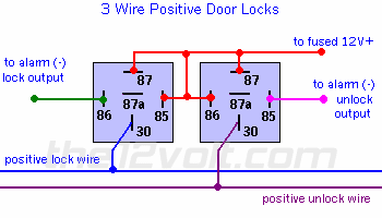
The wires you listed reperesent pins on a standard relay.
normally open, pin 87 the colors are yelow, and yellow/black.
normally closed, pins 87a the colors are orange, and orang/black.
common pins 30. The colors are white, and WHITE/ black
The opins 86, and 85 are controlled by the alarm brain. Take the normally open (yellow, yellow/black) to ground. never mind the fact that there are in line fuses they are there for posative door locks, your are negative.
Then take the common (white, WHITE/ black) to your lock and unlock wires in your car. Remember...you need to diode isolate the 2 unlock wires. When you need to "trigger" 2 wires with one output from your brain, theis one wire can allow current to flow from one wire to the other.
https://www.the12volt.com/diodes/diodes.asp Read about isolating negative triggers at the bottom left.
-------------
OK, one white wire doe the lock and the other stripe white wire does the unlock. Could I just run both white wires to the Actuator one to the green and the other to the Blue wire and connect the orange wire to the same green and blue wire according to its unlock and Lock.; So I would have a total of 4 wires to one Actuator - + + - since the remote sends each white wire its own signal? Thanks again for all your help... :)
Hope you can understand what I'm talking about.. I don't have any diodes and the Key less door company didn't say I would need any. Just don't want to make that trip or delay the installation if I can help it..
-------------
ETO
OK I Did it :).... Works great... what I did was what the Instructions told me to do.
Orange ground
White Actuator wire
Yellow - +12 volts, fused, constant
ORANGE / blk Ground
WHITE/ blk other actuator wire
Yellow/blk - +12 volts, fused, constant
Both Orange wires to vehicle Ground, White wire to Actuator Blue wire , WHITE/ Black stripe wire to Actuator Green wire ( reverse wires if remote does not correspond to there action Open/Close ) Both yellow wires to +12 volts constant ( without this Actuators would not work ) I used speaker wire to run the other Actuator to the white wires and that's it.. Thanks a lot guys for all your help and determination on bringing these Vague instructions to understanding :)
-------------
ETO