viper 350hv, 2004 f-150 supercrew
Printed From: the12volt.com
Forum Name: Car Security and Convenience
Forum Discription: Car Alarms, Keyless Entries, Remote Starters, Immobilizer Bypasses, Sensors, Door Locks, Window Modules, Heated Mirrors, Heated Seats, etc.
URL: https://www.the12volt.com/installbay/forum_posts.asp?tid=92999
Printed Date: March 25, 2026 at 8:07 AM
Topic: viper 350hv, 2004 f-150 supercrew
Posted By: dkal2980
Subject: viper 350hv, 2004 f-150 supercrew
Date Posted: April 16, 2007 at 9:18 AM
Could someone please help me with instruction of how to install a 350hv in my 2004 Lariat F150 supercrew? I have the wire diagrams and I have done a lot of searching on this forum. I have a couple questions about the power lock and unlock features. The Viper has a Power door lock harness, which is 3 pin. Is that the harness I use to connect the power lock and unlock switch to? Green from alarm to pink / YELLOW, and blue to pink/light green? [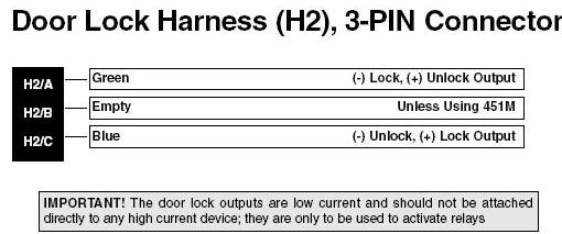 I have 4 doors is there a specific way to wire in the lock and unlock motor? I thought since I have the power lock wired in thats all I would need to activate the power locks. And finally the door triggers, do I have to wire that in using a relay and diodes? Thanks in advance for your help
Replies:
Posted By: Twelvoltz
Date Posted: April 16, 2007 at 9:57 AM
Door Locks: Yes, just tie the green to the pink / YELLOW and the blue to the pink/light green.
Hooking it up this way will not give you priority unlocking though. When you press lock it will lock all doors and when you press unlock it will unlock all doors, not the driver's first.
To do the door trigger correctly yes you would need to diode isolate all of the triggers. Some people just use the dome light wire for door trigger but there are drawbacks to the reliability of this method. Primarily if someone pulls the fuse for the dome light the door trigger will no longer respond.
-------------
Installer, IT support, and FFL. I need less hobbies.
Posted By: dkal2980
Date Posted: April 16, 2007 at 2:25 PM
I found this response from, "dea,can" with a diagram displaying the correct wiring of the door triggers to prevent false alarms when the body control module shuts down to save power. 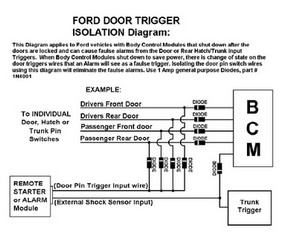
There is a green wire from the alarm identified as the neg door trigger input zone 3. Is that the wire I use to connect the door triggers using 2 diodes for each door trigger configuration shown in the diagram? The body control module in the rear of the cabin behind the rear seat, I may try and make my connections close to the BCM since the connector for all the wires are all in one location. In the same thread that I found the image from "dea,can". Kar TuneMan mentioned that only the front doors needed to be wired in. Then again the post was referring to a 2004 F150 lariat supercab. I don't know if the door triggers in the supercab share the same trigger. Can someone clarify this for me? The features I'm utilizing in my install are the door locks, door triggers, horn or siren and parking and dome lights to arm my vehicle. For this purpose is it necessary to tap into the ignition harness for Starter, Accessory voltages for the alarm module? I know I need constant 12 volts and Ignition. I want to minimize splicing into the factory wiring as much as possible. I have the diagrams with the help of the forum members here. Thank you for your responses.
Posted By: Twelvoltz
Date Posted: April 16, 2007 at 2:55 PM
That diagram is correct for diode isolation. DEI lists this for your door triggers:
Door Trigger BLACK/ yel (L), BLACK/ pink (R) - DKP, gray plug, pins 22, 23
With this note:
The wiring above is for vehicles without keyless entry. Vehicles with keyless entry, the door trigger wires are found at the BCM, green plug. The LF door trigger is BLACK / YELLOW in pin 4. The RF door trigger is BLACK/ pink in pin 5. The LR door trigger is BLACK/ lt. blue in pin 12. The RR door trigger is BLACK/ white in pin 13. Use all wires and diode isolate each.
-------------
Installer, IT support, and FFL. I need less hobbies.
Posted By: dkal2980
Date Posted: April 16, 2007 at 3:19 PM
dkal2980 wrote:
There is a green wire from the alarm identified as the neg door trigger input zone 3. Is that the wire I use to connect the door triggers using 2 diodes for each door trigger configuration shown in the diagram?
There are two door trigger inputs from the alarm positive and negative. I think I'm suppose to use the negative input. Am I correct in assuming this? dkal2980 wrote:
The features I'm utilizing in my install are the door locks, door triggers, horn or siren and parking and dome lights to arm my vehicle. For this purpose is it necessary to tap into the ignition harness for Starter, Accessory voltages for the alarm module? I know I need constant 12 volts and Ignition. I want to minimize splicing into the factory wiring as much as possible.
Do I need to connect the Starter and Accessory voltages going to the alarm. Can the alarm function with just 12 volts constant, and ignition? Twelvoltz, thank you
Posted By: Twelvoltz
Date Posted: April 16, 2007 at 4:53 PM
You would only use the negative door triggers listed in that note from DEI, correct.
There is no accessory input to the alarm, there is a starter kill output (orange ground when armed output). This is not a mandatory connection, it is an added layer of protection as your truck already has a factory transponder based anti theft system.
-------------
Installer, IT support, and FFL. I need less hobbies.
Posted By: dkal2980
Date Posted: April 21, 2007 at 7:17 PM
I almost completed the install for the viper 350hv. I did a preliminary test of the lock and unlock button on the remote and the power lock and unlock feature failed to work. I followed the diagram in my first post and it didn't work as I hoped. There are factory power locks. Wanted to use the viper remote to control the locks not the factory remote. Using the 3 pin, green blue wired to pink / YELLOW and pink/green for unlock and lock. I picked up the 2 wires at the DKP. Is there something I'm missing? The other options worked fine, just having problems with the lock and unlock feature on alarm. Thanks in advacne.
Posted By: dkal2980
Date Posted: April 21, 2007 at 9:12 PM
Wired the blue and green from the alarm to the unlock and lock connections at the Body control module. Lock feature is working now.
Posted By: enice
Date Posted: April 21, 2007 at 9:13 PM
Did you test the wires? or did you just find a wire and connected. A multimeter is your best friend so use your black lead and connect go ground. Using your read lead connect it to the WHITE/ red wire. As you control the lock switch it will go from 12v to 0v. This should be your lock/unlock testing method. Direct techs states that "With keyless entry(you have this) use WHITE/ red for lock and BLACK/ white for unlock. They are negative trigger and found at the VSM
Posted By: mikvot
Date Posted: April 21, 2007 at 9:19 PM
enice] wrote:
nbsp; Direct techs states that "With keyless entry(you have this) use WHITE/ red for lock and BLACK/ white for unlock. They are negative trigger and found at the VSM
These colors are for a super duty, the colors you have are correct...pink / YELLOW(-) lock ,pink green (-) unlock. -------------
Posted By: enice
Date Posted: April 21, 2007 at 9:32 PM
im sorry I got confused when I read "supercrew' thought it said superduty.. Either way use multimeter for verification.
Posted By: dkal2980
Date Posted: April 21, 2007 at 11:56 PM
Thanks for the information. I have a diagram and I originally went to a connector at the DKP. The pink/lg and pink / YELLOW were there behind the DKP. However I didn't use my multimeter. I was doing a quick test before I button the system up and found the locking feature wasn't working. So I decided to go the VSM and it worked out. Thanks
|