broke my remote start module pic inside
Printed From: the12volt.com
Forum Name: Car Security and Convenience
Forum Discription: Car Alarms, Keyless Entries, Remote Starters, Immobilizer Bypasses, Sensors, Door Locks, Window Modules, Heated Mirrors, Heated Seats, etc.
URL: https://www.the12volt.com/installbay/forum_posts.asp?tid=93546
Printed Date: April 17, 2026 at 4:26 PM
Topic: broke my remote start module pic inside
Posted By: crzysho
Subject: broke my remote start module pic inside
Date Posted: May 02, 2007 at 2:45 PM
Hi! I have installed a remote start (Autostart CT-5060) and I messed something up. I think there were too much power being draw through the ground out wire. (That wire that grounds when the remote start is running. So a little smokw came from the case, and I stopped the engine as soon as I saw this. But now that wire is always grounded no matter if there's power in the unit or not. I grabed my tester and tryed to look where the ground was traveling though. I took a picture and circled where I saw continuity between the wire #10 (ground out when running) and the point indicted in red. I think it should be a little device that acts like a relay, and just hope it's fixeable. Here's the picture. 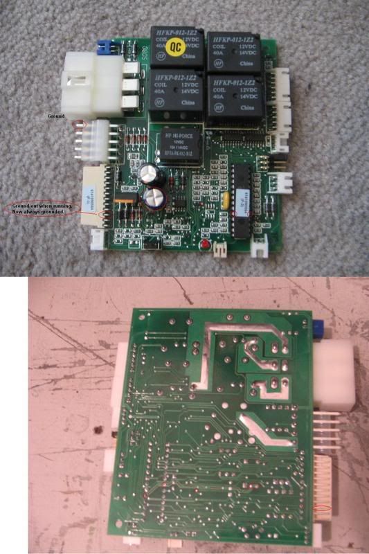
Thanks a lot guys ! ------------- 1995 Ford Taurus SHO
Replies:
Posted By: crzysho
Date Posted: May 02, 2007 at 2:50 PM
Since I can't find a way to edit : Here's the Full sized picture : https://fresh.4.life.free.fr/rs.JPG ------------- 1995 Ford Taurus SHO
Posted By: KPierson
Date Posted: May 02, 2007 at 3:12 PM
It's hard to say. The big circular thing is a capacitor, and wouldn't have any effect on things. The small red circle looks like it may be a transistor, but I doubt it is physically big enough to offer more then a 200mA output (no visable heat sink). The big socketed chip is most likely the firmware chip, but it is possible that it has a Darlington transistor output in it. I would contact the manufacturer about a warranty replacement.
-------------
Kevin Pierson
Posted By: crzysho
Date Posted: May 03, 2007 at 12:14 AM
I had previously replaced the unit that had broke that exact same way as this one. But now I've found my problem. So, what can, maybe beside that chip, can make that wire work (seems like it works like a relay) that can blow? I know how to solder and I study in electricity. Shouldn't be a problem to replace, but I need to find what's wrong. Thanks. ------------- 1995 Ford Taurus SHO
Posted By: KPierson
Date Posted: May 03, 2007 at 4:57 AM
The problem is most likely either a bad transistor or a bad output from the processor. ------------- Kevin Pierson
Posted By: fr0z3n
Date Posted: May 03, 2007 at 8:23 AM
I also have a ct prostart unit and I was wonder, what do you hook the ground out wire up to? should it be hooked up to a ground?
Posted By: crzysho
Date Posted: May 03, 2007 at 9:46 AM
Is there a way to test a transistor ? The unit turns on the ground wire 1 second before the start and 1 second after shut down. I just hope it's not the prossessor. frozen : That wire is connected to the negative side of the coil of a said relay, to use like : A clutch interlock bypass, or anything you'd need to power up with the remote start. ------------- 1995 Ford Taurus SHO
Posted By: KPierson
Date Posted: May 03, 2007 at 11:07 AM
Your best bet would to find the transistor on the board and then get a part number off of it. You can then find out if it is an NPN (most likely) or a PNP. If it is an NPN there shouldn't be any voltage on the base when you do NOT want an output. If the output is 'on' there should be ~5-12DC on the base of the transistor. I would hope that the transistor was damaged, as the uC output should be current limited to < 25mA. ------------- Kevin Pierson
Posted By: Chris Luongo
Date Posted: May 04, 2007 at 2:28 PM
You've got other options too, it'll just make the install a little more complex, and less neat-looking.
You could use your Ignition 2 output to drive two relays.
Configure one relay to put out a positive--this goes to Ignition 2 on the car.
Configure the other relay to put out a negative---here's your "groudn when running" output.
But, some cars don't even need a second ignition anyway....... what kind of car do you have, and what are you using for transponder bypass?
|