multiple relays share same common output
Printed From: the12volt.com
Forum Name: Car Security and Convenience
Forum Discription: Car Alarms, Keyless Entries, Remote Starters, Immobilizer Bypasses, Sensors, Door Locks, Window Modules, Heated Mirrors, Heated Seats, etc.
URL: https://www.the12volt.com/installbay/forum_posts.asp?tid=96056
Printed Date: March 26, 2026 at 11:13 PM
Topic: multiple relays share same common output
Posted By: frans-c
Subject: multiple relays share same common output
Date Posted: July 30, 2007 at 9:45 PM
I'd like to know whether two relays can share the same common output (terminal 30), e.g. on-board door lock relays of an alarm system and an SPDT relay controlled by a door lock switch sharing the same common output.
Or will the current from the one relay create a short-circuit within the other relay?
-------------
F R A N S
1985 Mercedes-Benz 230E
320 000 km / 199 000 miles
Full MB Service History
Replies:
Posted By: phonymike
Date Posted: July 31, 2007 at 12:25 AM
it'll only create a short circuit if + touched - in which case your fuse (should have a fuse) will blow. why use 2 relays? I've seen it done before, basically if you need more power. each relay can typically handle 30amps, so if you put 2 relays side by side (parallel not series!) they can handle 60amps together. I don't know if this is recommended though, as they have solenoids (big relays, not door poppers) that can handle like 100 and mor eamps. if both relays having the same output terminal, and also have the same input terminal (12 volts) then basically either relay can power the device, which is redundant, unless one relay is triggered with a - pulse, and the other relay is triggered with a + pulse. did any of that make any sense? maybe I'll whip up a drawing if it helps.
Posted By: frans-c
Date Posted: July 31, 2007 at 12:44 AM
I've created a similar thread on the relays forum as well as on this one, but I suspect I wrote too much...seems one has to keep it sweet and short!
I took another look at what I intend to do and came to the conclusion that I will indeed create a short circuit. I also realised that I won't have priority door unlocking if I don't incorporate a diode in the door lock switch.
This is my proposed setup:
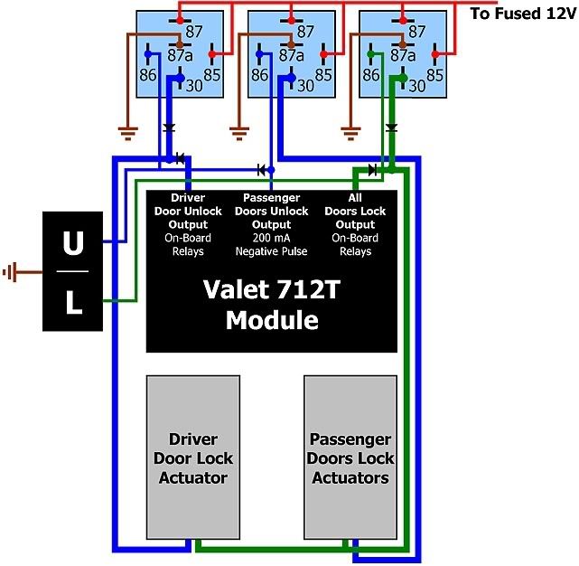
Does it look as if this setup will work? ------------- F R A N S
1985 Mercedes-Benz 230E
320 000 km / 199 000 miles
Full MB Service History
Posted By: howie ll
Date Posted: July 31, 2007 at 3:06 AM
Use 3amp diodes 5000 series on the terminal 30 cables. Loose the swith and save 2 relays!
Posted By: frans-c
Date Posted: July 31, 2007 at 8:06 AM
howie ll wrote:
Use 3amp diodes 5000 series on the terminal 30 cables. Loose the swith and save 2 relays!
Thanks for the tip - I actually read up a bit on the stuff and also came to the conclusion that I'll have to use higher capability diodes - 1N5405 perhaps.
Already have the switch, and the relays were really not that expensive!
I assume you agree with my setup then? ------------- F R A N S
1985 Mercedes-Benz 230E
320 000 km / 199 000 miles
Full MB Service History
Posted By: phonymike
Date Posted: July 31, 2007 at 9:28 AM
looking at your diagram, neither door will unlock, only the passenger will lock, there's no ground path in either direction for the driver's door cause you're blocking it with diodes. I don't like the idea of diodes running anything more than a signal, like to a relay either. anyone else have any qualms about designing a circuit that assumes that the lock and unlock state will never happen at the same time? also I don't see enough information. is the switch an aftermarket switch that could possibly be rewired to 12+? are there any factory relays that could help assist this situation? because looking at this, ignore your switch, I just figure hook up the driver's side actuator to both "driver's unlock" and "all doors lock" as normal. then using a relay, have 87 and 85 at 12+, 87a at ground. 30 would go to one side of the passenger actuator, and the other side of the actuator would go with "all doors unlock" assuming this output on the 712T rests at ground. can you post the instructions for this module? because as is it looks like a silly bitch to wire in an external switch. as is it looks like it'll power the driver's side door no problem, and adding 1 relay will add the passenger's door no problem, no diodes. maybe someone else can help but I don't see enough information.
Posted By: frans-c
Date Posted: July 31, 2007 at 11:09 AM
phonymike, I'm familiar with this unit; I installed it previously, but not with a switch. What's unclear about the diagram?
The 712T-module has on-board relays (shown in the diagram) for the driver's door unlock as well as the universal lock. Without the switch, I'll still need the center relay for the passenger doors unlock feature.
The reason I used diodes within the lines coming from the module's as well as the shown relays, is to prevent current "feedback" into the opposing relays. The diode within the passenger door's input line is to prevent the pulse from the driver's door unlock reaching the passenger door's unlock pulse when using the remote control, but allowing the switch to unlock all doors when it's used.
Am I missing something?
-------------
F R A N S
1985 Mercedes-Benz 230E
320 000 km / 199 000 miles
Full MB Service History
Posted By: frans-c
Date Posted: July 31, 2007 at 11:20 AM
Alright, I see where some confusion may arise. The thick blue and green lines coming out of the 712T module are both coming from terminals 30 from both relays.
I didn't deem it necessary to illustrate the rest of the on-board relays' terminals, but they are all wired correctly.
-------------
F R A N S
1985 Mercedes-Benz 230E
320 000 km / 199 000 miles
Full MB Service History
Posted By: phonymike
Date Posted: July 31, 2007 at 12:48 PM
take a look at your diagram. when the unlock is pressed from your switch, it it triggers the first relay giving the driver's door a nice 12+ on the blue wire on the left. where does the driver's actuator get a ground? the third relay is resting at ground, however a diode there blocks the ground (the cross line that the arrow points to is the cathode of a diode, ground can pass through the cross line) as well does the other diode coming from the 712t module. see it? again based on the information you've given, I think the easiest way to do this would be with three relays, no diodes. if this is anything like my alarm, we will use the 'driver unlock' as a ground output to unlock a new driver relay. the passenger unlock output will be the ground for a new passenger unlock relay. then the 'lock all doors' will be used as a ground output to lock them both. all relays have 87 and 85 going to 12+. all relays have 87a going to ground. 30 on the first relay goes to driver's actuator, 30 on the 2nd relay goes to passenger actuator, and 30 on the third relay goes to the other side on both actuators. at which point your unlock switch and 'driver's lock' on the module get tied together and go to 86 on the first relay. your 'passenger's unlock' on the module go to the second relay. then the lock switch and "lock all" go to the third relay. the two door relays rest at ground, so when the lock both doors relay gets energized, it sends the 12+ to the acuators to lock them both. otherwise the lock both doors relays rests at ground, so when you energize the driver or passenger relay, they send 12+ to unlock the actuator. it's just a waste of the built in relays in the 712t module but oh well.
Posted By: phonymike
Date Posted: July 31, 2007 at 1:12 PM
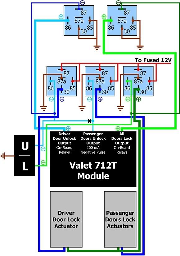
ain't it pretty? you do need 1 diode to isolate the driver's and passenger unlock, while still allowing the switch to do both. or leave it out it's up to you. there's no need to worry about 'feedback' or blowing fuses. if you somehow unlock the doors while locking them, the relays stay in a rested state at ground or 12+ so it does no damage.
Posted By: frans-c
Date Posted: July 31, 2007 at 1:41 PM
phonymike, thanks a lot! I actually thought of using a setup similar to the one you drew there, but like you said, I thought it would be a waste of the on-board relays.
And yes, I also realised that the diodes would nullify the grounding capabilities of the other relays.
All that's left to do know is to execute the master plan...  ------------- F R A N S
1985 Mercedes-Benz 230E
320 000 km / 199 000 miles
Full MB Service History
Posted By: frans-c
Date Posted: August 01, 2007 at 6:54 AM
I took another look at my diagram, as well as the one of phonymike's and came to the conclusion that neither my original diagram, nor the one that he proposes, is going to work.
The reason is that the switch supplies a negative trigger, whereas the 712T's on-board relays supply a positive 12V. I'm not too familiar yet with relays, but I'm almost certain a relay can't be triggered by a positive and negative trigger at the same time, can it?
I concluded that the positive 12V of the 712T's output first has to be converted to a negative trigger. Only then will I be able to use both the switch and relay's output to trigger the relays.
This is the diagram that I came up with:
------------- F R A N S
1985 Mercedes-Benz 230E
320 000 km / 199 000 miles
Full MB Service History
Posted By: phonymike
Date Posted: August 01, 2007 at 8:29 AM
again this is an assumption since you cannot provide me with more information on the module, but I assume the 'driver's unlock' is actually +unlock, -lock, while the 'all doors lock' is actually -unlock, +lock. what you should do is hook the module up. then read the two outputs with a multi meter. they should both show ground. then trigger it to unlock, one of them should show 12+. then trigger it to lock, the other should show 12+. if this is the case then my diagram will work.
Posted By: frans-c
Date Posted: August 01, 2007 at 9:46 AM
phonymike, here's the wiring harness from the 712T installation manual:
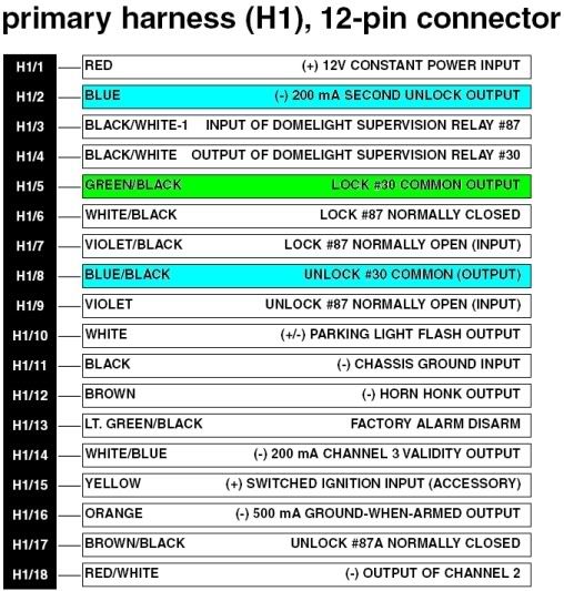
I'm almost certain that the common output terminals deliver positive 12V voltage. ------------- F R A N S
1985 Mercedes-Benz 230E
320 000 km / 199 000 miles
Full MB Service History
Posted By: phonymike
Date Posted: August 01, 2007 at 11:14 AM
boom that's what I'm talkin bout! now all you need is one relay for the second unlock and you're done, you just treat internal relays like you would normal ones.
Posted By: frans-c
Date Posted: August 01, 2007 at 1:37 PM
phonymike, what about my door lock switch then? Surely I'll have to incorporate at least three additional relays, considering that I'd like priority door unlocking.
That last post of yours was a bit vague...what did you mean by it exactly?
-------------
F R A N S
1985 Mercedes-Benz 230E
320 000 km / 199 000 miles
Full MB Service History
Posted By: phonymike
Date Posted: August 02, 2007 at 3:32 AM
yeah you're right, you still need 3 relays, and we'll just use the module to supply a ground output from the keyless, and tie it into your switch. - blue/black -> first relay 86 + switch (driver unlock)
- violet -> ground (source for unlock, throws a ground like your switch)
- blue -> second relay 86 + diode to driver's unlock wire/switch (pass unlock)
- GREEN/ black -> third relay 86 + switch (locks doors)
- violet/black -> ground (provides a ground to lock the doors)
use that and my diagram and you'll be set!
Posted By: frans-c
Date Posted: August 02, 2007 at 5:34 AM
That makes sense, yes!
Am I correct when I say that in the normally closed state, the modules on-board door lock relays should then rest at open, i.e. both terminals #87a (H1/6 and H1/17) will then not be used at all? (I only see know that Directed made a printing error with the description of wire H1/6  .)
When the coils of the on-board relays are energised, it will switch to normally open, thereby supplying the ground pulse to the other relays, right? ------------- F R A N S
1985 Mercedes-Benz 230E
320 000 km / 199 000 miles
Full MB Service History
|