adding door lock switches
Printed From: the12volt.com
Forum Name: Car Security and Convenience
Forum Discription: Car Alarms, Keyless Entries, Remote Starters, Immobilizer Bypasses, Sensors, Door Locks, Window Modules, Heated Mirrors, Heated Seats, etc.
URL: https://www.the12volt.com/installbay/forum_posts.asp?tid=96142
Printed Date: April 30, 2026 at 9:58 PM
Topic: adding door lock switches
Posted By: andyh24
Subject: adding door lock switches
Date Posted: August 03, 2007 at 1:40 PM
Hi everybody, I have a viper 600esp alarm installed with aftermarket actuators on my 2000 camaro. I am wanting to hook up some factory switches to operate the door locks. I know my alarm has internal relays to do the job. What do I need to do to hook up the switches to work along with my alarm? Any help would be greatly appreciated! Thanks!
Replies:
Posted By: andyh24
Date Posted: August 03, 2007 at 5:59 PM
By the way, the door lock actuators are DEI 524N if that matters.
Posted By: andyh24
Date Posted: August 04, 2007 at 8:48 AM
I noticed there are two wires coming out of my alarm. One is GREEN/ black and the other blue/black. My alarm has built in relays thus the actuators are connected directly to the alarm. There is a green and blue wire coming off of each actuator that goes to those two wires at the alarm. So, will I need to add two more relays outside of the alarm for my switches? If so, do I just hook the alarm wires to those extra relays?
Posted By: enice
Date Posted: August 04, 2007 at 9:04 AM
Well it looks like you do. The alarm has 87,87a, and 30. When I install actuators I use seperate relays to control the actuators. What triggers the actuators are 85 or 86 which the alarm does not provide externally. In this case I would suggest doing that and connecting one of your switch output wires to one of the 85's and the other output to the other. This should not be hard since the wires are already ran. Also the alarm must be rewired and connect the output to the 85's as well and ground the input wires from the alarm.
Posted By: howie ll
Date Posted: August 04, 2007 at 1:40 PM
No relays required. Use an electric window switch pref. from an aftermarket kit such as DAV brand switch. 5 connectors in a row, top is lock, to GREEN/ black to both motors, 2nd to GREEN/ black from alarm, third to 12v+ w. 15amp fuse or to the purple and PURPLE / black cables on alarm, 4th to blue/black from alarm, fith to blue/black on both motors. This is the same as a satellite window switch and doesn't affect the original circuit, it leaves both motor wires on ground at rest then brings one to live leaving he other at ground when pressed either way. Ah, that old timer window installation experience!
Posted By: andyh24
Date Posted: August 04, 2007 at 4:09 PM
Ok, would it be possible to use the factory door lock switches? They are 5 wire switches. I already have these switches and they are mounted in the factory locations. That is why I want to use them.
Posted By: howie ll
Date Posted: August 04, 2007 at 4:44 PM
Yes, follow factory wiring and alarm wiring as in 5 wire actuation.
Posted By: andyh24
Date Posted: August 05, 2007 at 7:02 PM
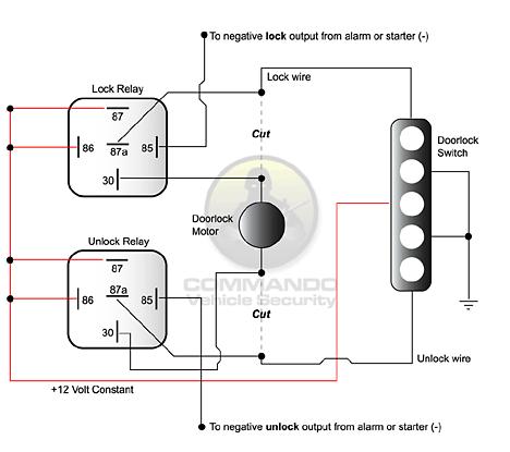
will this diagram work?
Posted By: howie ll
Date Posted: August 06, 2007 at 3:51 AM
Yes but you STILL don't need the relays!! Instead and refer to that very good diagramme you showed, take alarm outputs GREEN/ black and blue/black (30) to ground of switch, (shown coming from terminal 30 on relays), take switch connections shown coming from 87a to motor(s), take power supply ( marked +on switch) from purple PURPLE / black after the fuse which joins them (which should be 15 amps.
Posted By: andyh24
Date Posted: August 06, 2007 at 7:43 AM
Thanks! I will give that a try. One question though, the purple PURPLE / black wires coming off of my alarm (they are tied together with 15a fuse) are tied to a big red wire under my steering column. Do I leave them connected to the red wire and just tap in with another wire to run to my switches?
Posted By: andyh24
Date Posted: August 06, 2007 at 5:49 PM
Also, do I just do the same wiring to the passenger's side switch?
Posted By: howie ll
Date Posted: August 07, 2007 at 1:01 PM
No you take the lock outputs to motor and drivers' door AND back to passenger door along with 12v+ (disconnect lead from alarm to pass. door) Then use the 2 output wires to ground terminals, output terminals 2 pass. door motor and live to centre tap. You might have to change output leads around at switches in the worst case you will blow the fuse. Sorry about forgetting to tell you!
Posted By: howie ll
Date Posted: August 07, 2007 at 1:17 PM
Yes, AFTER the fuse but when you say TAP I assume you mean solder join, not scotch locks or other similar rubbish!
Posted By: andyh24
Date Posted: August 07, 2007 at 5:50 PM
Yeah, I'm going to solder all of my connections. I am little confused by how I am supposed wire both switches though. I guess I need to figure out what each pin does on the switch. Each of my switches have 5 pins and they are not labeled.
Posted By: howie ll
Date Posted: August 08, 2007 at 2:31 AM
This is where you learn how to use a DMM 
|