Print Page | Close Window

switches and door popper problem

Printed From: the12volt.com
Forum Name: Car Security and Convenience
Forum Discription: Car Alarms, Keyless Entries, Remote Starters, Immobilizer Bypasses, Sensors, Door Locks, Window Modules, Heated Mirrors, Heated Seats, etc.
URL: https://www.the12volt.com/installbay/forum_posts.asp?tid=96383
Printed Date: April 27, 2024 at 1:42 PM


Topic: switches and door popper problem

Posted By: joshmcdowall
Subject: switches and door popper problem
Date Posted: August 14, 2007 at 3:46 AM

hi i have install a door popper kit to my alarm on my holden rodeo 1988 tf ute it is set up so when the 2nd unlock pulse goes the drivers door pops open and another trigger open the passenger side door..

the problem im having is the button i use in the interior ive set up to pop the door has to much power going through it..  i think its only rated 15amps so it keeps frying and i really want to use those type of buttons...

this is how its set up now

posted_image

my question is would i be able to set it up this way to have less power running through the button or would this fry the alarm system or something bad.

posted_image

oh...  and if the second diagram works how do i reduce power going through the button? use thinner wire? or use a fuse as shown.?

and should there be a  fuse running on the +12v constant line before the relay for the solenoids or should i just leave it unfused.

im quite new to this stuff and any help would be great. thanks


Replies:

Posted By: Phreak480
Date Posted: August 14, 2007 at 7:20 AM
wire the button to activate a relay as well

or you could probably have the alarm and the button each activate the relay using diodes for separation. someone else please chime in i'm about to run out the door to work


Posted By: steezs
Date Posted: August 14, 2007 at 10:17 AM

Most alarms use negative pulses for the lock and unlock in relays that change the pulses into stronger 12volt signals,  why dont you wire the button to send a ground to the 85 of the relays. The second diagram is right except just take the power supply off the other side of the button and ground it instead and fuse the 86 and 87 to 12 volts with 15 amps and leave 30 its good.


-------------
THE DUCE


Posted By: steezs
Date Posted: August 14, 2007 at 10:18 AM
That way no power is going through the button at all just ground.

-------------
THE DUCE


Posted By: steezs
Date Posted: August 19, 2007 at 3:52 PM
posted_image

-------------
THE DUCE


Posted By: steezs
Date Posted: August 19, 2007 at 3:56 PM
posted_image
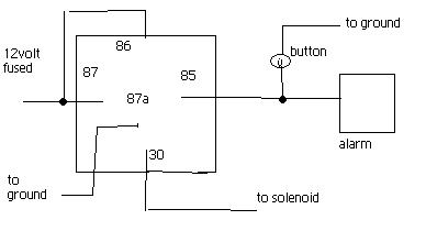
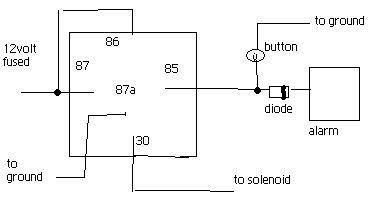
You need to put the diode too ,sorry.

-------------
THE DUCE


Posted By: joshmcdowall
Date Posted: August 19, 2007 at 9:59 PM
oh ok thanks for that.. will give it  go. does 87a need to be grounded though?


Posted By: b2reptile
Date Posted: August 20, 2007 at 11:12 AM
  I would not hook 87a to anything.


Posted By: steezs
Date Posted: August 20, 2007 at 11:22 AM

Maybe its just for actuators that it needs to be grounded try without first, just makes sure you put the fuse though


-------------
THE DUCE


Print Page | Close Window